

Sealey SAC3203B3PH Instructions For Use Manual
INSTRUCTIONS FOR:
COMPRESSOR 200LTR BELT DRIVE 3.0HP
415V/3PH WITH FRONT CONTROL PANEL
MODEL NO: SAC3203B3PH
Thank you for purchasing a Sealey product. Manufactured to a high standard, this product will, if used according to these instructions
and properly maintained, give you years of trouble free performance.
IMPORTANT: PLEASE READ THESE INSTRUCTIONS CAREFULLY. NOTE THE SAFE OPERATIONAL REQUIREMENTS, WARNINGS & CAUTIONS. USE THE
PRODUCT CORRECTLY AND WITH CARE FOR THE PURPOSE FOR WHICH IT IS INTENDED. FAILURE TO DO SO MAY CAUSE DAMAGE AND/OR PERSONAL
INJURY AND WILL INVALIDATE THE WARRANTY. KEEP THESE INSTRUCTIONS SAFE FOR FUTURE USE.
1. SAFETY
1.1 ELECTRICAL SAFETY.
WARNING! It is the user’s responsibility to read, understand and comply with the following:
You must check all electrical equipment and appliances to ensure they are safe before using. You must inspect power supply leads, plugs and all
electrical connections for wear and damage. You must ensure the risk of electric shock is minimised by the installation of appropriate safety
devices. An RCCB (Residual Current Circuit Breaker) should be incorporated in the main distribution board. We also recommend that an RCD
(Residual Current Device) is used with all electrical products. It is particularly important to use an RCD together with portable products that are
plugged into an electrical supply not protected by an RCCB. If in doubt consult a professional electrician. You may obtain a Residual Current
Device by contacting your Sealey dealer. You must also read and understand the following instructions concerning electrical safety.
1.1.1 The Electricity At Work Act 1989 requires all portable electrical appliances, if used on business premises, to be tested by a qualified
Electrician at least once a year, using a Portable Appliance Tester (PAT).
1.1.2 The Health & Safety at Work Act 1974 makes owners of electrical appliances responsible for the safe condition of the appliance, and the
safety of the appliance operator. If in any doubt about electrical safety, contact a qualified Electrician.
1.1.3 Ensure the insulation on all cables and the product itself is safe before connecting to the mains power supply. See 1.1.1. & 1.1.2.
above and use a Portable Appliance Tester (PAT).
1.1.4 Ensure that cables are always protected against short circuit and overload.
1.1.5 Regularly inspect power supply, leads, plugs and all electrical connections for wear and damage, especially power connections, to ensure that
none are loose.
1.1.6 Important: Ensure the voltage marked on the product is the same as the electrical power supply to be used and check that plugs are fitted with the correct
capacity fuse. If an electrical fuse blows, ensure it is replaced with an identical fuse type and rating.
1.1.7 DO NOT pull or carry the powered appliance by its power supply lead or output cables.
1.1.8 DO NOT pull power plugs from sockets by the power cable.
1.1.9 DO NOT use worn or damage leads, plugs or connections. Immediately replace or have repaired by a qualified Electrician. This
particular compressor is supplied without a mains plug. Follow the instructions below regarding the fitting of an appropriate plug.
1.2 MODEL SAC3203B3PH REQUIRES A 415V 3 PHASE SUPPLY AND MUST HAVE AN APPROPRIATE PLUG FITTED.
WARNING! ELECTRICAL INSTALLATION OF THE COMPRESSOR TO A 3 PHASE 415VOLT SUPPLY MUST ONLY BE CARRIED OUT BY A
QUALIFIED ELECTRICIAN. Ensure the power supply cable is connected to the Earth.
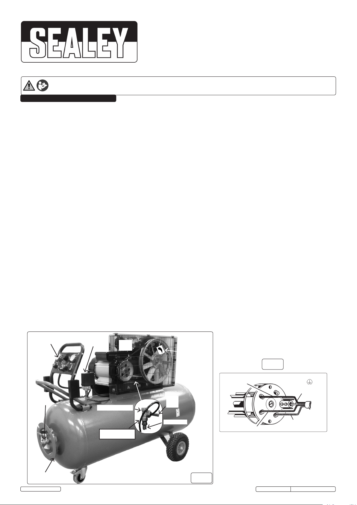
1.2.1 This product must be fitted with a 3 phase plug wired as illustration in (fig.2), wired to an appropriately fused supply.
Connect GREEN/YELLOW wire to Earth ‘E’
Connect BROWN wire to L1 Terminal.*
Connect BLACK wire to L2 Terminal.*
Connect the GREY wire to L3 Terminal.*
*NOTE: The cable core colours found in the mains cable on this compressor are consistent with Amendment 2 to 7671:2001. When completed,
check there are no bare wires, that all wires have been connected correctly and the cable restraint is tight.
WARNING! IT IS ESSENTIAL TO OBSERVE ANTI-CLOCKWISE (fig.1) PULLEY DIRECTION ON INITIAL START UP. IF CLOCKWISE
OBSERVED, STOP IMMEDIATELY AND CONSULT A QUALIFIED ELECTRICIAN TO INVERT 2 PHASES.
1.2.2 DO NOT use this product with a standard extension cable. Only use ARMOURED extension cable
IMPORTANT USER INFORMATION! Over-current protection of the power circuit is required in accordance with 7.2 of EN 60204-1:2006. The
supply disconnecting device to be in accordance with 5.3 of EN60204-1:2006. Ask a qualified electrician about compliance. The use of extension
leads to connect these compressors to the mains is not recommended.
Control Panel
(g.7)
Switches
(g.8)
Motor
3~ph
Pump
(g.5)
IMPORTANT!
Anti-clockwise
rotation
(label on guard)
see 1.2.1
fig.2
(Grey) to L3 'E' Earth
green/yellow
Ball valve
Hose reel tidy
© Jack Sealey Limited
Non return valve
Receiver
Swivel castor with brake
Decompression
tube from switch
From
pump
To receiver
2-Pneumatic
tyres 1.5bar
fig.1
Original Language Version
(Black) to L2
Mains
cable
(Brown) to L1
SAC3203B3PH Issue No: 1 - 27/10/14

1.3. GENERAL SAFETY
3 Familiarise yourself with the application and limitations of the compressor.
3 Ensure the compressor is in good order and condition before use. If in any doubt DO NOT use the unit and contact an electrician/
service agent.
WARNING! The Compressor must only be serviced by an authorised agent. DO NOT tamper with, or attempt to adjust,
pressure switch or safety valve.
3 Before moving, or maintaining the compressor ensure it is unplugged from the mains supply and that the air tank pressure has been
vented.
3 Maintain the compressor in good condition and replace any damaged or worn parts. Use genuine parts only. Unauthorised parts may
be dangerous and will invalidate your warranty.
3 Read the instructions relating to any accessory to be used with this compressor. Ensure the safe working pressure of any air appliance
used exceeds compressors output pressure. If using a spray a gun, check that the area selected for spraying is provided with an air
change/ventilation system.
3 Ensure the air supply valve is turned off before disconnecting the air supply hose.
3 Move the compressor on a pallet or using slings beneath receiver near to domed ends, employing a fork lift truck or wheeled gantry
crane. Beware of off centre loads.
3 Use the compressor in a well ventilated area and ensure it is placed on a firm surface.
3 Keep tools and other items away from the compressor when it is in use, and keep area clean and clear of unnecessary items.
3 Ensure the air hose is not tangled, twisted or pinched.
3 Keep children and unauthorised persons away from the working area.
3 When not in use, store the compressor carefully in a safe, dry, childproof location.
7 DO NOT disassemble compressor for any reason. The unit must be checked by qualified personnel only.
7 DO NOT use the compressor outdoors, or in damp, or wet, locations.
7 DO NOT operate the compressor within the vicinity of flammable liquids, gases or solids.
7 DO NOT touch the compressor cylinder head or pipe from the head to tank as these may be hot.
7 DO NOT use this compressor to perform a task for which it has not been designed.
7 DO NOT deface the certification plate attached to the compressor tank.
7 DO NOT cover the compressor or restrict air flow around the unit whilst operating.
q DANGER! DO NOT direct the output jet of air towards people or animals.
7 DO NOT operate the compressor without an air filter.
7 DO NOT allow anyone to operate the compressor unless they have received full instructions.
WARNING! The air tank is a pressure vessel and the following safety measures apply:
7 DO NOT tamper with the safety valve, DO NOT modify or alter the tank in any way and DO NOT strap anything to the tank.
7 DO NOT subject the tank to impact, vibration or to heat and no welding operations are to be carried out on any pressurised parts of
the vessel. DO NOT allow contact with abrasives or corrosives.
2. INTRODUCTION
V-pump belt driven compressor, 200ltr. The pump features heavy duty fully cast cylinders, capped by alloy heads for improved heat dissipation
and long life. Suitable for professional workshop applications. The 2 cylinder pump is powered by a 415v 3ph 3.0hp motor. A precision,
continuously welded receiver tank manufactured to meet Pressure Vessel Directive 2009/105/EC. Fitted with fully automatic pressure cut-out
switch and receiver drain valve. Supplied with 2 pneumatic tyred wheels, a leading swivel castor, fixings and 4 core 2.5 metre flying lead.
3. SPECIFICATION
MODEL: ......................................................................SAC3203B3PH
Motor output: .....................................................................2.2kW/3hp
Voltage/phase: ..................................................................415V - 3ph
Rated supply: ..................................................................................6A
Speed at pump:.....................................................................1243rpm
Noise level: ............................................................................96dB(A)
Air displacement cfm (ltr/min): ........................................ 13.4 (380)
Maximum free air delivery cfm (ltr/min): ......................... 10.9 (310)
Tank capacity: ............................................................................200ltr
Max pressure: ...............................................................145psi /10bar
Weight: ......................................................................................103kg
Dimensions (W x D x H): ...............................1410 x 600 x 1020mm
4. ASSEMBLY
4.1. Remove compressor from packaging and inspect for any shortages or damage. If anything is found to be missing or damaged
contact your supplier.
4.2. Save the packing material for future transportation of the compressor. We recommend that you store the packing in a safe location, at
least for the period of the guarantee. Then, if necessary, it will be easier to send the compressor to the service centre.
4.3. Confirm that the mains voltage corresponds with the voltage shown on the compressor data plate.
4.4. Assemble the 2 wheels and leading swivel castor, using the nuts, bolts and washers supplied (fig.4).
4.5. The compressor should be operated on a flat surface, or one that does not exceed 5° either transversely or longitudinally
and should be in a position that allows good air circulation around the unit, (see 1000mm nominal perimeter in fig.6).
4.6. Before using the compressor check the oil level by referring to the oil sight glass (fig.5C). On a horizontal surface, if the oil level is not
up to the red centre mark it should be further topped up with recommended oil (See section 6.7). To top up unscrew plug (fig.5B).
4.7. Screw the back half of a filter unit into the port openings in each head as shown in (fig.5A and fig.3). Place a filter cover over each
threaded rod protruding from the back half of the filter and secure each with a wing nut.
4.8. Check the drain valve is fully closed (fig.9)
5. OPERATION
WARNING! Ensure that you have read, understood and apply Section 1 safety instructions.
5.1. IMPORTANT. The use of extension leads to connect this compressor to the mains is not recommended as the resulting
voltage drop reduces motor, and therefore pump, performance and could damage your compressor.
5.2. Take care when selecting tools for use with the compressor. Air tool manufacturers normally express the volume of air
required to operate a tool in cubic feet per minute (cfm). This refers to free air delivered by the compressor (‘air out’) which
varies according to the pressure setting. Do not confuse this with the compressor displacement which is the air taken in by
the compressor (‘air in’). ‘Air out’ is always less than ‘air in’ due to losses within the compressor.
© Jack Sealey Limited
Original Language Version
SAC3203B3PH Issue No: 1 - 27/10/14
 Loading...