

Page 1
PORTABLE AIR CON/DEHUMIDIFIER/COOLER/
IMPORTANT: PLEASE READ THESE INSTRUCTIONS CAREFULLY. NOTE THE SAFE OPERATIONAL REQUIREMENTS, WARNINGS &
CAUTIONS. USE THE PRODUCT CORRECTLY AND WITH CARE FOR THE PURPOSE FOR WHICH IT IS INTENDED. FAILURE TO DO
SO MAY CAUSE DAMAGE AND/OR PERSONAL INJURY AND WILL INVALIDATE THE WARRANTY. KEEP THESE INSTRUCTIONS SAFE
FOR FUTURE USE.
HEATER WITH WINDOW KIT
MODEL NO: SAC12000.V5
Thank you for purchasing a Sealey product. Manufactured to a high standard, this product will, if used according to these instructions,
and properly maintained, give you years of trouble free performance.
This unit uses a ammable refrigerant.
If refrigerant leaks and comes in contact with re or heating
part, it will create harmful gas and there is risk of re.
Refer to
instruction
Do not cover Caution:
Indoor use only
Risk of re
Read the USER MANUAL carefully before operation.
1. SAFETY
1.1. ELECTRICAL SAFETY
WARNING! It is the user’s responsibility to check the following:
9 Check all electrical equipment and appliances to ensure that they are safe before using. Inspect power supply leads, plugs
and all electrical connections for wear and damage. Sealey recommend that an RCD (Residual Current Device) is used with
all electrical products.
Electrical safety information. It is important that the following information is read and understood:
9 Ensure that the insulation on all cables and on the appliance is safe before connecting it to the power supply.
9 Regularly inspect power supply cables and plugs for wear or damage and check all connections to ensure that they are secure.
Important: Ensure that the voltage rating on the appliance suits the power supply to be used and that the plug is tted with the correct fuse.
8 DO NOT pull or carry the appliance by the power cable.
8 DO NOT pull the plug from the socket by the cable.
8 DO NOT use worn or damaged cables, plugs or connectors. Ensure that any faulty item is repaired or is replaced immediately
by a qualied electrician.
If the cable or plug is damaged during use, switch o the electricity supply and remove from use.
Ensure that repairs are carried out by a qualied electrician.
9 If the supply cord is damaged, it must be replaced by the manufacturer, its service agent or similarly qualied persons in order to avoid a hazard.
CAUTION: In order to avoid a hazard due to inadvertent resetting of the thermal cut-out, this appliance must not be supplied through
an external switching device, such a timer, or connected to a circuit that is regularly switched on and o by the utility.
1.2. GENERAL SAFETY
9 Check that the unit is in sound condition and good working order. Take immediate action to repair or replace damaged parts.
NOTE: this appliance is for professional repair only.
9 Use recommended parts only. Unauthorised parts may be dangerous and will invalidate the warranty.
NOTE: Appliance is lled with R290.
9 Appliance shall be installed, operated and stored in a room with a oor area larger than 12m².
8 DO NOT perforate any of the components in the refrigerant circuit. Refrigerant gas may be odourless.
8 DO NOT attempt any repairs / maintenance unless suitably qualied.
8 DO NOT stand or place any object closer than 500mm from the unit.
8 DO NOT obstruct the air intakes or outlets of the unit, and DO NOT cover with washed clothes.
8 DO NOT place any object into the outlets - the unit has a fan running at high speed, contact with this will cause injury.
8 DO NOT operate the unit when you are tired or under the inuence of alcohol, drugs or intoxicating medication.
8 DO NOT switch the unit o by disconnecting it from the mains. ALWAYS switch to the “OFF” position rst.
8 DO NOT remove the oat lever from the water collection tank.
8 DO NOT connect or disconnect the plug from the mains with wet hands.
9 Always discard the water from the collection tank, DO NOT use it for any other purpose.
9 Place the unit on a level and stable surface.
9 To prevent water from freezing, DO NOT use the unit at ambient temperatures below 0°C.
8 DO NOT use the unit outside.
8 DO NOT expose to rain, moisture or any other liquid.
9 Ensure that heating appliances are not exposed to the ow of air from the unit.
9 Before attempting to move the unit, empty the contents of the water tank. Use side carrying handles when moving unit.
9 Switch o and disconnect unit from the mains before attempting any cleaning or other maintenance work.
9 Ensure that the unit is turned o correctly when not in use, and stored in a safe, dry area, out of reach of children.
9 Children from age 8 years and above, persons with reduced physical, sensory, or mental capabilities those with lack of experience and
knowledge can use the appliance, if they have been given supervision or instruction concerning use of the appliance in a safe way to
understand the hazards involved.
8 DO NOT allow children to play with the appliance.
8 DO NOT allow children to perform cleaning or user maintenance on the appliance without supervision.
9 The appliance shall be disconnected from its power source during service and when replacing parts and, if that the removal of the plug
is foreseen, it shall be clearly indicated that the removal of the plug has to be such that an operator can check from any of the points to
© Jack Sealey Limited
which he has access that the plug remains removed.
Original Language Version
SAC12000.V5 Issue 2 (5) 11/01/24
Page 2
8 DO NOT immerse or expose the unit to rain, moisture or any other liquid.
8 DO NOT leave the unit running unattended. Do not tilt or turn over the unit.
8 DO NOT unplug while the unit is operating.
9 The unit is designed only for use with R-290(propane) gas as the designated
refrigerant.
9 The refrigerant loop is sealed. Only a qualied technician should attempt to
service.
8 Do not discharge the refrigerant into the atmosphere.
9 R-290 (propane) is ammable and heavier than air. It collects rst in low
areas but can be circulated by the fans.
8 If propane gas is present or even suspected, DO NOT allow untrained
personnel to attempt to nd the cause.
9 The propane gas used in the unit has no odor. The lack of smell does not
indicate a lack of escaped gas.
9 If a leak is detected, immediately evacuate all persons from the area,
ventilate the room and contact the local re department to advise them that a
propane leak has occurred.
8 DO NOT let any persons back into the room until the qualied service
technician has arrived and that technician advises that it is safe to return to
the room.
8 No open ames, cigarettes or other possible sources of ignition should be
used inside or in the vicinity of the units.
9 Component parts are designed for propane and non-incentive and non-
sparking. Component parts shall only be replaced with identical repair parts.
WARNING! FAILURE TO ABIDE BY THIS WARNING COULD RESULT IN
AN EXPLOSION, DEATH, INJURY AND PROPERTY DAMAGE.
2. INTRODUCTION
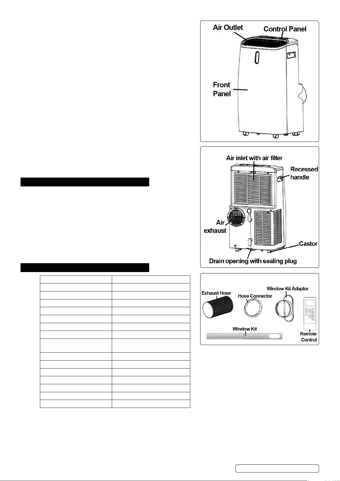
4-in1 high capacity, compact, portable air conditioner, air cooling with
ventilation, dehumidifying and heating functions. Thermostatically controlled
with built-in 24hr timer and sleep mode. Soft-touch control panel with LED
digital display and remote control. Self-evaporating system reuses the
moisture it collects from the air to help with the cooling process allows better
eciency, low maintenance and powerful cooling. Water-full indicator with
auto-shut-o. Supplied with extendable exhaust ducting with window kits
for extraction. Dehumidifying function capable of removing up to 30.3L/
day and includes continuous drain hose. Eco-Friendly R290 refrigerant.
Air conditioning temperature range 16-32°C. Washable lter. Auto-defrost
function at low ambient temperature. Mounted on castor wheels for
manoeuvrability.
3. SPECIFICATION
MODEL NO: SAC12000.V5
Cooling Capacity: 12000Btu/hr
Discharge Side Pressure: 3.2MPa
Energy Rating: A (EER: 2.6)
IP Rating: IPX1
Mass of Refrigerant: 240g
Maximum Airow: 410m³/hr
Maximum Exhaust Hose Length: 1.5m
Maximum Water Extraction
Rate:
Noise Level: 65dB(A)
Power Supply Cable Length: 1.8m
Power: 1337W (Cooling), 1118W (Heating)
Rated Capacity: 3520W (Cooling), 2780W (Heating)
Refrigerant: R290
Suction Side Pressure: 0.7MPa
Supply: 230V ~ 50Hz
30.3L/day
© Jack Sealey Limited
Original Language Version
SAC12000.V5 Issue 2 (5) 11/01/24
Page 3
4. INSTALLATION
4.1. BEFORE INSTALLATION
Check the device for any damage or missing parts.
4.2. CHOOSE YOUR LOCATION
NOTE: If tipped more than 45°, allow the unit to set upright for at least 24 hours before start up.
4.2.1. Place the unit on a rm, level surface in an area with at least 50cm of free space around it to allow for proper air circulation.
8 DO NOT operate in close proximity to walls, curtains, or other objects that may block air inlet and outlet. Keep the air inlet and outlet
free of obstacles.
8 DO NOT install the unit where it could be subject to:
• Heat sources such as radiators, heat registers, stoves or other products that products that produce heat.
• Direct sunlight
• Mechanical vibration or shock
• Excessive dust
• Lack of ventilation, such as cabinet or bookcase
• Uneven surface
WARNING! Install the unit in rooms which exceed 12m².
8 DO NOT install the unit in a place where inammable gas may leak.
4.3. ATTACH THE EXHAUST HOSE
The air conditioner must be vented outside to remove exhaust air from the room.
8 DO NOT extend the exhaust hose which will result in decreased eciency, even worse shut down the unit due to low back-pressure.
4.3.1. Adjusting the length of the exible exhaust hose, and avoid bends in the hose. Then place AC near an electrical outlet.
4.3.2. Adjust the louver at the air outlet, and then switch on the unit.
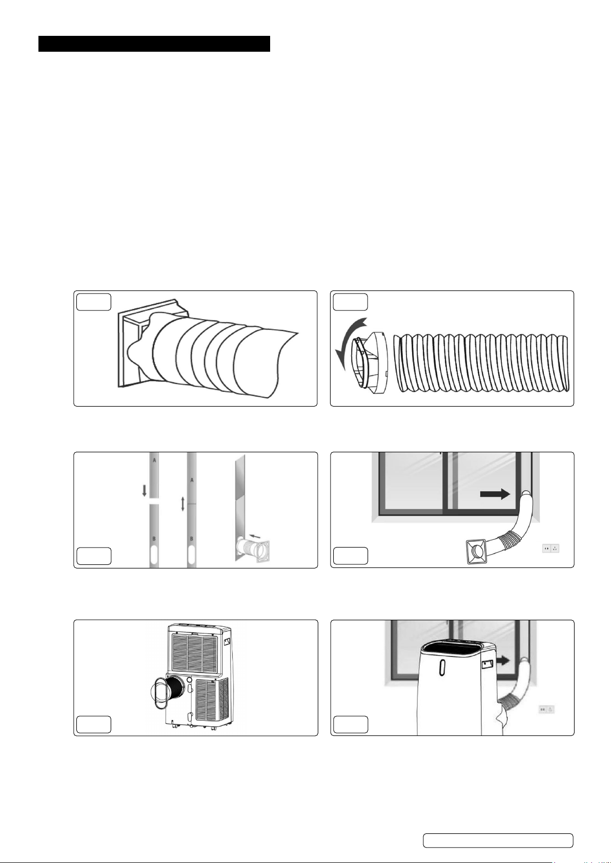
FIG.1
4.4.1. Connect the hose connector to one end of the exhaust
hose (g.1)
FIG.3
4.4.3. Extend the adjustable window kit to the length of your
window. Connect the exhaust hose to the window kit
(g.3).
FIG.2
4.4.2. Connect the windows kit adapter to the other end of the
exhaust hose (g.2).
FIG.4
4.4.4. Close the window to secure the kit in place. Secure the
window kit with duct tape if required (g.4).
FIG.5
4.4.5. Attach the hose connector to the exhaust air outlet of
© Jack Sealey Limited
unit (g.5).
Original Language Version
FIG.6
4.4.6. Avoid bends in the hose. Plug in to power supply. (g.6).
SAC12000.V5 Issue 2 (5) 11/01/24
Page 4
5. OPERATION
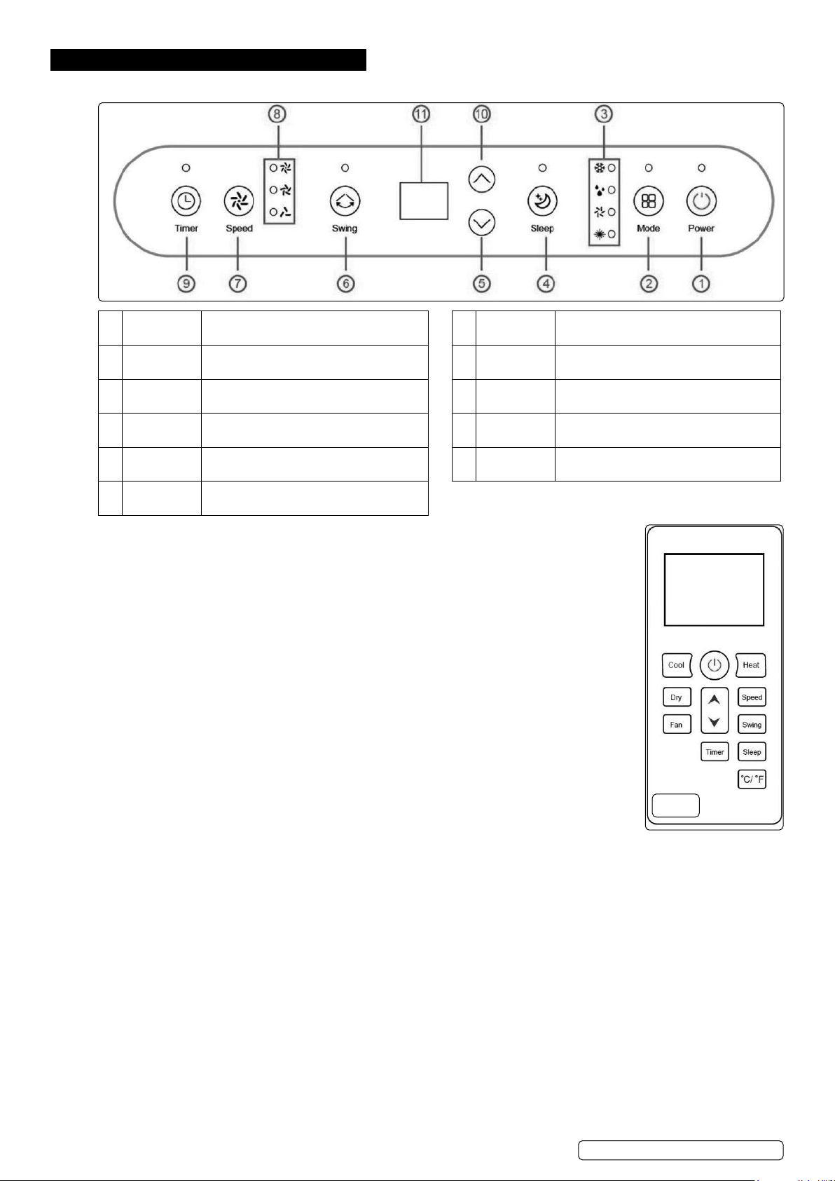
5.1. CONTROL PANEL & DISPLAY
1 POWER Press to switch the machine on or o. 7 SPEED Press to switch the fan speed from high,
2 MODE Press to switch the operation mode
between cool, dry, fan and heat.
3 MODE
indicator
4 SLEEP Press to turn sleep mode on or o. 10 UP Increase the desired temperature (16-
5 DOWN Decrease the desired temperature or
6 SWING Adjust the air ow direction vertically.
Indicates the MODE setting - cool, dry, fan
and heat.
timer settings.
medium and low speed.
8 SPEED
indicator
9 TIMER Sets a time for the unit to automatically
11 DIGITAL
DISPLAY
Indicates the SPEED setting - high,
medium low.
start or stop.
32oC)
Displays timer setting and temperature.
NOTE: the above functions can also be performed on the remote control (g.6).
5.2. START-UP & SHUTDOWN
5.2.1. Press POWER to turn the unit on. The unit runs in FAN as default.
5.2.2. Press MODE button to select the desired operation mode.
5.2.3. Press POWER again to turn o the power.
5.3. OPERATION MODES
The unit has ve operation modes: Cool, dehumidify, fan, heat, sleep
5.4. COOLING
Select the cool mode to lower the temperature in your room.
5.4.1. Press MODE button repeatedly until the LED of COOL operation lights up.
5.4.2. Press Up/Down button to adjust the temperature which is displayed on the screen. The temperature can be
set between 16oC and 32oC.
5.4.3. Press SPEED button repeatedly until the desired fan speed indicator lights up.
5.4.4. To control the direction of the air ow horizontally, press the SWING button on.
NOTE: The air conditioner stops if the room temperature is lower than selected temperature.
5.5. HEATING
5.5.1. Press MODE button repeatedly until the LED of HEAT operation lights up.
5.5.2. Press ADD/MINUS button to set the temperature higher than the room temperature. The fan speed can
also be set.
5.6. VENTILATING
5.6.1. Press MODE button repeatedly until the LED of FAN operation lights up. In ventilation mode the room air is circulated, but not cooled.
5.6.2. Press SPEED button repeatedly to select the fan speed as desired.
5.7. DRYING/DEHUMIDIFYING YOUR ROOM
5.7.1. Press MODE button on the control panel or remote control, the LED of DRY operation lights up.
5.7.2. The drainage hose should be attached to the unit for continuous operation.
NOTE: In this mode, the fan speed switches over to low speed and the temperature cannot be selected.
FIG.6
5.8. SLEEP MODE
The sleep mode can be activated when in cool mode and heat mode.
5.8.1. In cool mode:
After 1 hour the preset temperature is increased by 1oC, after another hour the preset temperature will again be increased by 1oC.
5.8.2. In heat mode:
After 1 hour the preset temperature is decreased by 1oC, after another hour the preset temperature will again be decreased by 1oC.
The temperature is then kept constant for 10 hours and all indicators dim. The fan speed will switch over to low speed for silent
operation, and cannot be selected.
© Jack Sealey Limited
Original Language Version
SAC12000.V5 Issue 2 (5) 11/01/24
Page 5
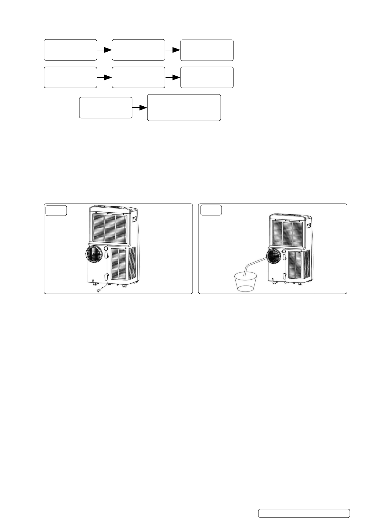
5.9. TIMER SETTINGS
The timer has two ways of operation:
TO TURN OFF
(when power on)
TO TURN ON
(when power o)
CANCEL TIMER
5.10. AUTOMATIC DEFROST
At low room temperatures, frost may build up at the evaporator during operation. The unit will automatically start defrosting and the
POWER LED will start blinking. The defrost control sequence is as follows:
5.10.1. When the unit operates in the cooling operation, drying operation, the ambient temperature sensor senses the evaporator coil
temperature is below -1°C, after the compressor will stop operating for 10 minutes or the coil temperature up to 7oC, the unit restart to
cool operating mode.
5.10.2. When the unit operates in the heating operation, drying operation, once the coil temperature sensor senses the temperature of the
evaporator is below 40oC and the dierential temperature between coil temperature and room temperature is below 19oC after the
compressor operation for 20minutes, the unit start defrosting for 5 minutes and the power indicator blinking.
5.11. OVERLOAD PROTECTION
In the event of a power loss, there is a 3 minute delay before the appliance will restart.
Press TIMER key
to turn on the timer
function
Press TIMER key
to turn on the timer
function
Press UP/DOWN repeatedly
until the LED shows ‘00’.
NOTE: pressing POWER will
also exit the timer setting.
FIG.7
Press UP/DOWN
repeatedly to set the
delay OFF time.
Press UP/DOWN
repeatedly to set the
delay ON time.
FIG.8
MANUAL
DRAINAGE
5.12. DRAINAGE
The unit has two methods of drainage. These are manual (g.7, point 5.13) or continuous (g.8, point 5.14).
5.13. MANUAL DRAINAGE (FIG.7)
5.12.1. Turn o the appliance once the water is full.
5.12.2. Unplug the appliance from the power supply.
NOTE: If moving the machine, do it carefully so you do not spill water in the pan at the bottom of the body.
5.12.3. Place a container underneath the waste water outlet.
5.12.4. Remove the sealing plug and gently title the appliance backwards to aid drainage. Water will ow into the container.
5.12.5. Replace the sealing plug.
NOTE: It is recommended to restart the appliance afterwards to reduce condensation running onto the oor.
8 DO NOT submerge the end of hose into water; otherwise it can cause “Air Lock” in the hose.
NOTE: TO AVOID WATER SPILLAGE. As the negative pressure of condensate drain pan is large, tilt the drain hose downward toward
the oor. It is appropriate that the degree of inclination should exceed 20 degrees. Straighten the hose to avoid a trap existing in the hose.
5.14. CONTINUOUS DRAINAGE (FIG.8)
The self-evaporating system uses the collected water to cool the condenser coils for better ecient performance. It is no need to empty
the drainage tank in cooling operation except in drying operation and high humidity conditions. The condensate water evaporates at
the condenser and evacuated through the exhaust hose. For continuous operation or unattended operating in drying operation, please
connect the attached drain hose to the unit. Condensate water can be automatically ow into a bucket or drain by gravity.
5.13.1. Switch o the unit before operating.
5.13.2. Remove the plug of the water outlet opening, and keep it in safe area.
5.13.3. Securely and properly connect the drain hose and make sure it is not kinked and clear of obstruction.
5.13.4. Place the outlet of hose over a drain or bucket and ensure that water could freely ow out of the unit.
5.13.5. Do not submerge the end of hose into water; otherwise it can cause “Air Lock” in the hose.
5.13.5. To avoid water spillage:
• As the negative pressure of condensate drain pan is large, tilt the drain hose downward toward the oor. It is appropriate that the
degree of inclination should exceed 20 degrees.
• Straighten the hose to avoid a trap existing in the hose.
CONTINUOUS
DRAINAGE
© Jack Sealey Limited
Original Language Version
SAC12000.V5 Issue 2 (5) 11/01/24
Page 6
6. MAINTENANCE
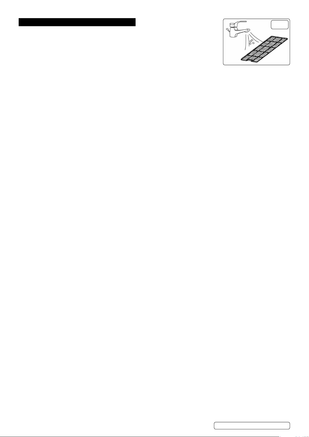
6.1. CLEANING THE AIR FILTER (FIG.9)
The air lter is removable for easy cleaning. The lters are situated at the rear of the unit, and are
held in place by plastic frames.
8 DO NOT operate the unit without an air lter, or the evaporator may be contaminated.
6.1.1. Press the POWER button to switch o the unit. Unplug the power cord.
6.1.2. Remove the lter mesh from the unit.
To remove the upper lter: Using the nger grip, pull the top edge gently outwards to release
the holding lugs and remove the lter frame.
To remove the lower lter: Undo xing screw and pull the frame gently outwards to release the holding lugs and remove lter frame.
6.1.3. Use a vacuum cleaner to suck dust from the lter.
6.1.4. Turn the lter over and rinse the air lter under running water. Let the water run through the lter in the opposite direction of air ow.
6.1.5. Set aside and allow the lter to air dry completely before reinstalling.
NOTE: Retting the lter frames into the machine is the reverse of 6.1.2.
6.2. CLEANING UP OF REFRIGERANT
6.2.1. Gas/vapour heavier than air. May accumulate in conned spaces, particularly at or below ground level.
6.2.2. Eliminate every possible source of ignition.
6.2.3. Use appropriate personal protection equipment (PPE).
6.2.4. Evacuate unnecessary personnel, isolate, and ventilate area.
8 DO NOT get in eyes, on skin, or on clothing.
8 DO NOT breathe vapours or gas.
6.2.5. Prevent entry to sewers and public waters.
6.2.6. Stop the source of the release, if safe to do so. Consider the use of water spray to disperse vapours.
6.2.7. Isolate the area until gas has dispersed. Ventilate and gas test area before entering. Contact competent authorities after a spill.
6.3. STORAGE
6.3.1. If you will not be using the unit for an extended period of time (more than a few weeks) it is best to clean the unit and dry it out
completely. Please store the unit per the following steps:
6.3.2. Unplug the unit and remove exhaust hose and window kit.
6.3.3. Drain the remaining water from the unit via the drainage stopper (g.7).
6.3.4. Clean the lter and let it dry completely in a shaded area.
6.3.5. Re-install the lter.
6.3.6. Store the unit in an upright position, in a well-ventilated, dry location.
6.4. FLAMMABLE REFRIGERANTS USED - R290 GAS SAFETY
6.4.1. CHECKS TO THE AREA
Prior to beginning work on systems containing ammable refrigerants, safety checks are necessary to ensure that the risk of ignition is
minimised. For repair to the refrigerating system, the following precaution shall be completed prior to conducting work on the system.
6.4.2. WORK PROCEDURE
Work shall be undertaken under a controlled procedure so as to minimise the risk of a ammable gas or vapour being present while the
work is being performed.
6.4.3. GENERAL WORK AREA
All maintenance sta and others working in the local area shall be instructed on the nature of work being carried out. Work in conned
spaces shall be avoided.
6.4.4. CHECKING FOR PRESENCE OF REFRIGERANT
The area shall be checked with an appropriate refrigerant detector prior to and during work, to ensure the technician is aware of
potentially toxic or ammable atmospheres. Ensure that the leak detection equipment being used is suitable for use with all applicable
refrigerants, i.e. non-sparking, adequately sealed or intrinsically safe.
6.4.5. PRESENCE OF FIRE EXTINGUISHER
If any hot work is to be conducted on the refrigerating equipment or any associated parts, appropriate re extinguishing equipment shall
be available to hand. Have a dry powder or CO2 re extinguisher adjacent to the charging area.
6.4.6. NO IGNITION SOURCES
No person carrying out work in relation to a refrigerating system which involves exposing any pipe work shall use any sources of
ignition in such a manner that it may lead to the risk of re or explosion. All possible ignition sources, including cigarette smoking,
should be kept suciently far away from the site of installation, repairing, removing and disposal, during which refrigerant can possibly
be released to the surrounding space. Prior to work taking place, the area around the equipment is to be surveyed to make sure that
there are no ammable hazards or ignition risks. “No Smoking” signs shall be displayed.
6.4.7. VENTILATED AREA
Ensure that the area is in the open or that it is adequately ventilated before breaking into the system or conducting any hot work. A
degree of ventilation shall continue during the period that the work is carried out. The ventilation should safely disperse any released
refrigerant and preferably expel it externally into the atmosphere.
6.4.8. CHECKS TO THE REFRIGERATING EQUIPMENT
Where electrical components are being changed, they shall be t for the purpose and to the correct specication. At all times, the
manufacturer’s maintenance and service guidelines shall be followed. If in doubt, consult the manufacturer’s technical department for
assistance. The following checks shall be applied to installations using ammable refrigerants:
• The actual refrigerant charge is in accordance with the room size within which the refrigerant containing parts are installed.
• The ventilation machinery and outlets are operating adequately and are not obstructed.
• If an indirect refrigerating circuit is being used, the secondary circuit shall be checked for the presence of refrigerant.
• Marking to the equipment continues to be visible and legible. Markings and signs that are illegible shall be corrected.
• Refrigerating pipe or components are installed in a position where they are unlikely to be exposed to any substance which may
corrode refrigerant containing components, unless the components are constructed of materials which are inherently resistant to being
corroded or are suitably protected against being so corroded.
6.4.9. CHECKS TO ELECTRICAL DEVICES
Repair and maintenance to electrical components shall include initial safety checks and component inspection procedures. If a fault
FIG.9
© Jack Sealey Limited
Original Language Version
SAC12000.V5 Issue 2 (5) 11/01/24
Page 7

exists that could compromise safety, then no electrical supply shall be connected to the circuit until it is satisfactorily dealt with. If the
fault cannot be corrected immediately but it is necessary to continue operation, an adequate temporary solution shall be used. This
shall be reported to the owner of the equipment so all parties are advised. Initial safety checks shall include:
• That capacitors are discharged: this shall be done in a safe manner to avoid possibility of sparking.
• That no live electrical components and wiring are exposed while charging, recovering or purging the system.
• That there is continuity of earth bonding.
6.4.10. REPAIRS TO SEALED COMPONENTS
During repairs to sealed components, all electrical supplies shall be disconnected from the equipment being worked upon prior to
any removal of sealed covers, etc. If it is absolutely necessary to have an electrical supply to equipment during servicing, then a
permanently operating form of leak detection shall be located at the most critical point to warn of a potentially hazardous situation.
Particular attention shall be paid to the following to ensure that by working on electrical components, the casing is not altered in such a
way that the level of protection is aected. This shall include damage to cables, excessive number of connections, terminals not made
to original specication, damage to seals, incorrect tting of glands, etc. Ensure that the apparatus is mounted securely. Ensure that
seals or sealing materials have not degraded to the point that they no longer serve the purpose of preventing the ingress of ammable
atmospheres. Replacement parts shall be in accordance with the manufacturer’s specications.
6.4.11. REPAIR TO INTRINSICALLY SAFE COMPONENTS
DO NOT apply any permanent inductive or capacitance loads to the circuit without ensuring that this will not exceed the permissible
voltage and current permitted for the equipment in use. Intrinsically safe components are the only types that can be worked on while
live in the presence of a ammable atmosphere. The test apparatus shall be at the correct rating. Replace components only with parts
specied by the manufacturer. Other parts may result in the ignition of refrigerant in the atmosphere from a leak.
6.4.12. CABLING
Check that cabling will not be subject to wear, corrosion, excessive pressure, vibration, sharp edges or any other adverse
environmental eects. The check shall also take into account the eects of aging or continual vibration from sources such as
compressors or fans.
6.4.13. DETECTION OF FLAMMABLE REFRIGERANTS
Under no circumstances shall potential sources of ignition be used in the searching for or detection of refrigerant leaks. A halide torch
(or any other detector using a naked ame) shall not be used.
Removal and evacuation When breaking into the refrigerant circuit to make repairs – or for any other purpose – conventional
procedures shall be used. However, for ammable refrigerants it is important that best practice is followed since ammability is a
consideration. The following procedure shall be adhered to:
• Remove refrigerant;
• Purge the circuit with inert gas;
• Evacuate;
• Purge with inert gas;
• Open the circuit by cutting or brazing.
The refrigerant charge shall be recovered into the correct recovery cylinders. For appliances containing ammable refrigerants the
system shall be purged with oxygen-free nitrogen to render the appliance safe for ammable refrigerants. This process may need to
be repeated several times. Compressed air or oxygen shall not be used for purging refrigerant systems. For appliances containing
ammable refrigerant, purging shall be achieved by breaking the vacuum in the system with oxygen-free nitrogen and continuing to
ll until the working pressure is achieved, then venting to atmosphere, and nally pulling down to a vacuum. This process shall be
repeated until no refrigerant is within the system. When the nal oxygen-free nitrogen charge is used, the system shall be vented down
to atmospheric pressure to enable work to take place. This operation is absolutely vital if brazing operations on the pipe-work are to
take place.
Ensure that the outlet for the vacuum pump is not close to any potential ignition sources and that ventilation is available.
6.4.14. CHARGING PROCEDURES
In addition to conventional charging procedures, the following requirements shall be followed.
• Ensure that contamination of dierent refrigerants does not occur when using charging equipment. Hoses or lines shall be as short as
possible to minimise the amount of refrigerant contained in them.
• Cylinders shall be kept in an appropriate position according to the instructions.
• Ensure that the refrigerating system is earthed prior to charging the system with refrigerant.
• Label the system when charging is complete (if not already).
• Extreme care shall be taken not to overll the refrigerating system.
Prior to recharging the system, it shall be pressure-tested with the appropriate purging gas. The system shall be leak-tested on
completion of charging but prior to commissioning. A follow up leak test shall be carried out prior to leaving the site.
6.4.15. DECOMMISSIONING
Before carrying out this procedure, it is essential that the technician is completely familiar with the equipment and all its detail. It is
recommended good practice that all refrigerants are recovered safely. Prior to the task being carried out, an oil and refrigerant sample
shall be taken in case analysis is required prior to re-use of recovered refrigerant.
It is essential that electrical power is available before the task is commenced.
A) Become familiar with the equipment and its operation.
B) Isolate system electrically.
C) Before attempting the procedure, ensure that:
• Mechanical handling equipment is available, if required, for handling refrigerant cylinders.
• All personal protective equipment is available and being used correctly.
• The recovery process is supervised at all times by a competent person.
• Recovery equipment and cylinders conform to the appropriate standards.
D) Pump down refrigerant system, if possible.
E) If a vacuum is not possible, make a manifold so that refrigerant can be removed from various parts of the system.
F) Make sure that cylinder is situated on the scales before recovery takes place.
G) Start the recovery machine and operate in accordance with instructions.
H) Do not overll cylinders (no more than 80 % volume liquid charge).
I) Do not exceed the maximum working pressure of the cylinder, even temporarily.
J) When the cylinders have been lled correctly and the process completed, make sure that the cylinders and the equipment are
© Jack Sealey Limited
Original Language Version
SAC12000.V5 Issue 2 (5) 11/01/24
Page 8
removed from site promptly and all isolation valves on the equipment are closed o.
K) Recovered refrigerant shall not be charged into another refrigerating system unless it has been cleaned and checked.
6.4.16. LABELLING
Equipment shall be labelled stating that it has been de-commissioned and emptied of refrigerant. The label shall be dated and signed.
For appliances containing ammable refrigerants, ensure that there are labels on the equipment stating the equipment contains
ammable refrigerant.
6.4.17. RECOVERY
When removing refrigerant from a system, either for servicing or decommissioning, it is recommended good practice that all
refrigerants are removed safely.
When transferring refrigerant into cylinders, ensure that only appropriate refrigerant recovery cylinders are employed. Ensure that the
correct number of cylinders for holding the total system charge is available. All cylinders to be used are designated for the recovered
refrigerant and labelled for that refrigerant (i.e. special cylinders for the recovery of refrigerant). Cylinders shall be complete with
pressure-relief valve and associated shut-o valves in good working order. Empty recovery cylinders are evacuated and, if possible,
cooled before recovery occurs.
The recovery equipment shall be in good working order with a set of instructions concerning the equipment that is at hand and shall
be suitable for the recovery of all appropriate refrigerants including, when applicable, ammable refrigerants. In addition, a set of
calibrated weighing scales shall be available and in good working order. Hoses shall be complete with leak-free disconnect couplings
and in good condition. Before using the recovery machine, check that it is in satisfactory working order, has been properly maintained
and that any associated electrical components are sealed to prevent ignition in the event of a refrigerant release. Consult manufacturer
if in doubt.
The recovered refrigerant shall be returned to the refrigerant supplier in the correct recovery cylinder, and the relevant waste transfer
note arranged. Do not mix refrigerants in recovery units and especially not in cylinders.
If compressors or compressor oils are to be removed, ensure that they have been evacuated to an acceptable level to make certain
that ammable refrigerant does not remain within the lubricant. The evacuation process shall be carried out prior to returning the
compressor to the suppliers.
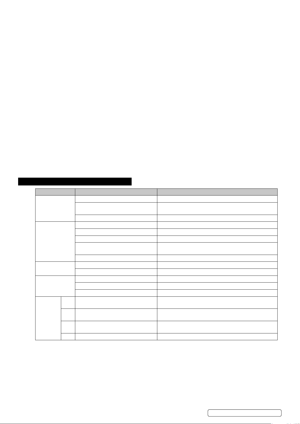
7. TROUBLESHOOTING
SYMPTOM INSPECTION SOLUTION
The unit is not
working
The unit works with
reduced capacity
Water Leakage Overow while moving the unit. Empty the water tank before transport.
Excessive Noise Check if the unit is securely positioned. Place the unit on horizontal and rm ground.
Error
Codes
Check the mains supply Insert the power cord securely into the wall outlet
Check if the water level indicator lights
up?
Check the room temperature. The range of operating temperature is 5-35oC
Check if the air duct is blocked Clear the obstacle.
Check the air lter for dirt Clean the air lter. See Section 7
Check if the room door or window is open. Keep the door and windows closed.
Check if the desired operating mode is
selected and temperature is properly set.
The exhaust hose is detached. Make sure the exhaust hose is securely attached.
Check if the drain hose is kinked or bent. Straighten the hose to avoid a trap existing.
Check if any loose, vibrating parts. Secure and tighten the parts.
Noise sounds like water owing. Noise comes from owing refrigerant. This is normal.
E0 Communication faults between main PCB
and display PCB.
E1 Ambient temperature sensor failure Check connection or replace it. To clean or replace the
E2 Coil temperature sensor failures. Check connection or replace it. To clean or replace the
Ft Condensate water high level alarm. Empty the drain pan. See Section 5.10
Empty the drain pan. See Section 5.10
Set the mode and temperature at proper set-point
See Section 5
Check the wire harness of the display PCB for damage.
temperature sensor.
temperature sensor.
© Jack Sealey Limited
Original Language Version
SAC12000.V5 Issue 2 (5) 11/01/24
Page 9
WINDOW SEALING KIT FOR AIR CONDITIONER DUCTING
MODEL NO: SACWK1
8. SAFETY
8 DO NOT cover the unit with this material, and do not obstruct the air inlet and outlet grilles of the machine with items such as
clothing,soft furnishings, furniture, bedding etc.
8 DO NOT use the material for any purpose other than that for which it is designed.
8 DO NOT use in bathroom or shower room.
8 DO NOT allow children to use, when not in use,store in a safe, cool, dry, childproof area.
NOTE: This material is not intended for use by persons (including children) with reduced physical, sensory or mental capabilities or
lack of experience and knowledge, unless they have been given supervision or instruction concerning the use of the appliance by a
person responsible for their safety. Children should be supervised to ensure that they do not play with this material.
9. INTRODUCTION
Suitable for all types of hinged windows including skylights up to 300cm total perimeter. Easy to install using the supplied roll of selfadhesive hook & loop tape. Double zip makes positioning the ducting at any height easy. Saves energy by making the air conditioner or
dryer more eective.
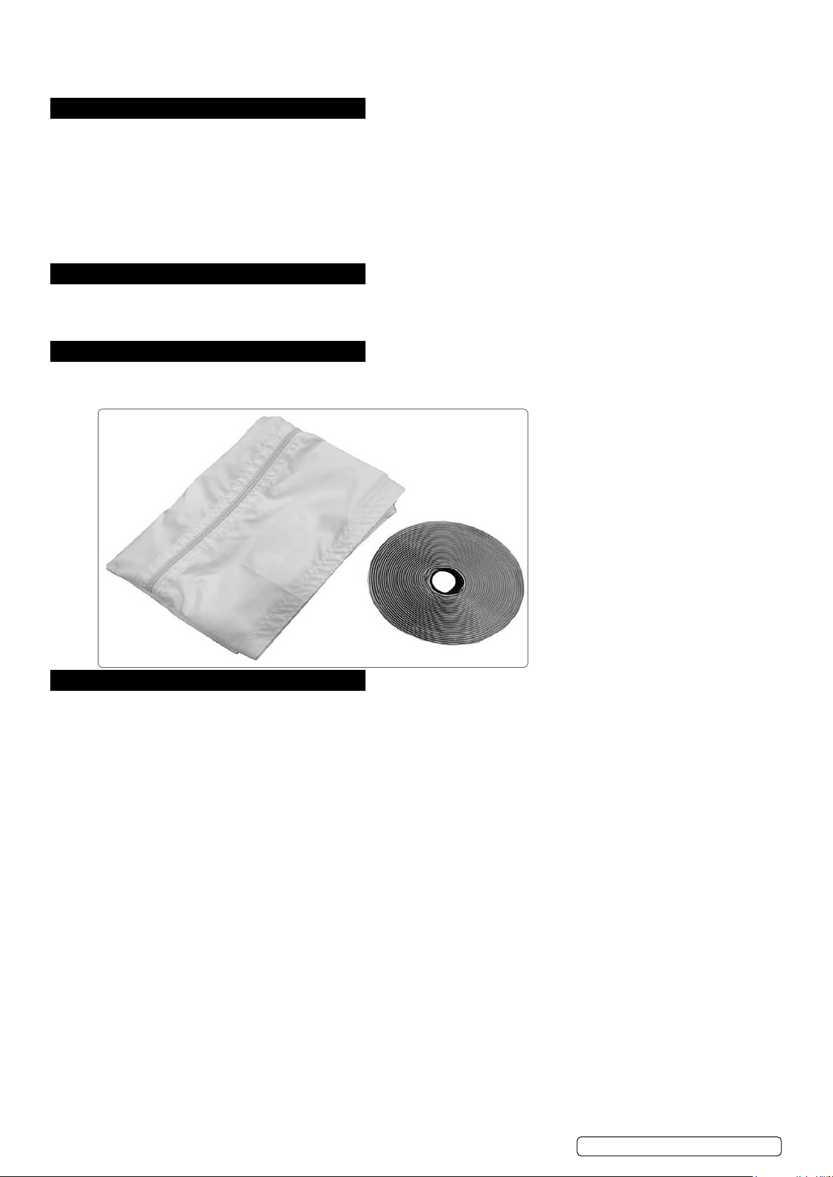
10. CONTENTS
Window seal
Velcro tape
Velcro tape
Window seal with zip
11. INSTRUCTIONS
11.1. CLEANING
Clean the window and window frame, making them free from grease and dust.
11.2. CUTTING THE VELCRO TAPE TO SIZE
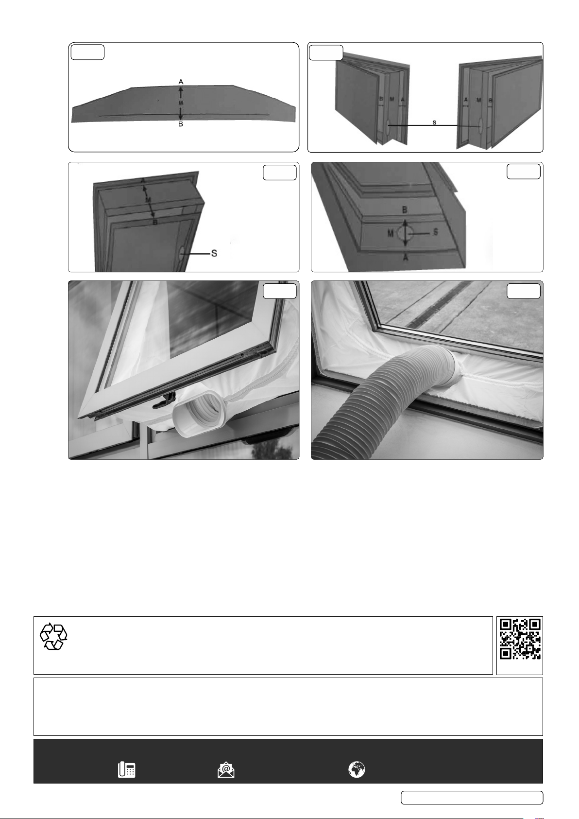
Cut the Velcro tape to size, using a pair of scissors. Mark the middle (M) of the window seal (g.10). Mark the middle of the window
frame and the casement (Fig. 11 to 13) ( g. 11 shows an open window, g.12 a tilted window and g.13 an open skylight).
11.3. VELCRO TAPE TO THE WINDOW FRAME
Adhere the Velcro tape to the window frame around the window. Then adhere the Velcro tape fully around the window. Stick the Velcro
tape to the front side (in most cases 1 cm wide) of the casement or to the inner surface of the casement (where the window handle is
attached).
CAUTION: DO NOT adhere the Velcro tape on the window.
11.4. SEALING WINDOW TO WINDOW FRAME
Adhere the narrow side of the window seal to the Velcro tape on the window frame. Work from the centre and fully adhere the
narrow side all the way around. First fasten side A, then side B, starting in the middle and working all the way to the left and right.
IMPORTANT! When fastening, point A must be exactly opposite point B.
11.5. SEALING THE WINDOW
Leave the window ajar and adhere the wide side of the window seal to the Velcro tape of the window.
CAUTION: Leave sucient space, so that the window seal will not get jammed
11.6. OPENING THE WINDOW SEAL
Open the zip of the window seal approximately 50 cm. Open the zip preferably at the positions marked with “S” and attach the exhaust
air hose.
11.7. ATTACHING THE AIR DISCHARGE
Insert the air discharge hose of the air conditioning system through the hole in the window seal and close the zip until the air discharge
hose is properly secured
11.8. CLOSING THE WINDOW
If you want to close your window, simply detach the cloth from the Velcro tape. When closing the window take care that the seal is not
jammed between the casement and window frame.
NOTE: This window seal ensures that the room remains cool for a longer period of time and keeps insects and mosquitoes out.
© Jack Sealey Limited
Original Language Version
SAC12000.V5 Issue 2 (5) 11/01/24
Page 10
g.10
PURCHASE HERE
POLYESTER
MATERIAL
g.11
M = MIDDLE
g.12
TILTED WINDOW
g.14 g.15
OPEN WINDOW
g.13
OPEN SKYLIGHT
11.9. The installed item resemble g.14 and g.15.
ENVIRONMENT PROTECTION
Recycle unwanted materials instead of disposing of them as waste. All tools, accessories and packaging should be
sorted, taken to a recycling centre and disposed of in a manner which is compatible with the environment. When
the product becomes completely unserviceable and requires disposal, drain any uids (if applicable) into approved
containers and dispose of the product and uids according to local regulations.
Note: It is our policy to continually improve products and as such we reserve the right to alter data, specications and component parts
without prior notice. Please note that other versions of this product are available. If you require documentation for alternative versions, please
email or call our technical team on [email protected] or 01284 757505.
Important: No Liability is accepted for incorrect use of this product.
Warranty: Guarantee is 12 months from purchase date, proof of which is required for any claim.
REGISTER YOUR
© Jack Sealey Limited
Sealey Group, Kempson Way, Suffolk Business Park, Bury St Edmunds, Suffolk. IP32 7AR
Original Language Version
SAC12000.V5 Issue 2 (5) 11/01/24
Page 11
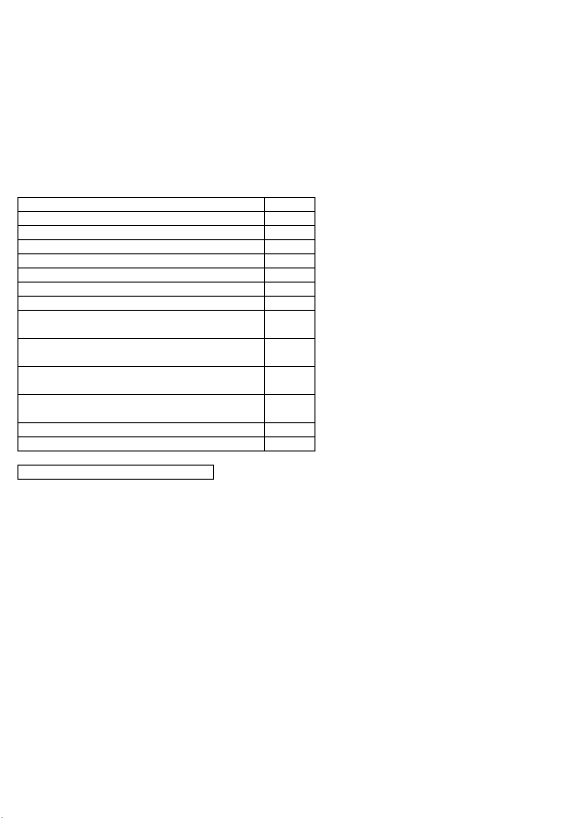
Product Information Sheet. Air Conditioners.
SUPPLIER_NAME_OR_TRADEMARK Sealey EU Ltd.
DELEGATED_ACT 206/2012/EU
MODEL_IDENTIFIER SAC12000
ADDRESS
Farney Street, Carrickmacross, Co. Monaghan, A81 PK68 Ireland
PHONE_NUMBER 01284 757 500
EMAIL_ADDRESS [email protected]
Parameter
Verification tolerances
3.5
2.8
1.1
1.1
2.6
2.5
0.0
0.5
1.3
65
3
Suppliers website https://www.sealey.co.uk/
Power consumption in thermostat-off mode W
Air Conditioner/Dehumidifier/Heater 12,000Btu/hr
Rated Capacity for cooling kW
Rated capacity for heating kW
Power input for cooling kW
Power input for heating kW
Rated Energy efficiency ratio
Rated coefficient of performance
Sound power level LWA dB
Global warming potential GWP kg
Power consumption in standby mode W
Electricity consumption of single duct appliances
kWh/h Cooling
Electricity consumption of single duct appliances
kWh/h Heating
Electricity consumption of double duct appliances
kWh/a Cooling
Electricity consumption of double duct appliances
kWh/a Heating
1.1
NA
NA
 Loading...