

Sealey RE2311 Instructions Manual
© Jack Sealey Limited
Original Language Version
INSTRUCTIONS FOR:
COIL SPRING COMPRESSING STATION
HYDRAULIC 2000kg CAPACITY - WITH GAUGE
MODEL NO: RE2311
IMPORTANT: PLEASE READ THESE INSTRUCTIONS CAREFULLY. NOTE THE SAFE OPERATIONAL REQUIREMENTS, WARNINGS & CAUTIONS. USE THE PRODUCT
CORRECTLY AND WITH CARE FOR THE PURPOSE FOR WHICH IT IS INTENDED. FAILURE TO DO SO MAY CAUSE DAMAGE AND/OR PERSONAL INJURY AND WILL
INVALIDATE THE WARRANTY. KEEP THESE INSTRUCTIONS SAFE FOR FUTURE USE.
Thank you for purchasing a Sealey product. Manufactured to a high standard, this product will, if used according to these instructions
and maintained properly, give you years of trouble free performance.
Refer to Instruction
Manual
1. SAFETY
GENERAL SAFETY.
WARNING! Ensure Health & Safety, local authority, and general workshop practice regulations are adhered to when using this equipment.
WARNING!Wear approved safety hand and eye protection (standard spectacles are not adequate).
WARNING! TRAPPING DANGER – Keep hands and fingers away from the spring and compressing yokes in use.
Keep the work area clean, uncluttered and ensure there is adequate lighting.
Maintain correct balance and footing. Ensure the floor is not slippery and wear non-slip shoes.
Remove ill-fitting clothes. Remove ties, watches, rings, other loose jewellery. Contain and/or tie back long hair.
Wear appropriate protective clothing.
Familiarise yourself with the applications, limitations and potential hazards of the spring compressor.
DO NOT force the spring compressor to achieve a task it was not designed to perform.
DO NOT allow untrained persons to use the spring compressor.
BEFORE USE
WARNING: Coil Spring Compression station should be securely bolted to the workshop floor before use.
Apply grease to the front and rear faces of the main upright to assist the smooth action of the compressor.
DO NOT operate spring compressor if parts are damaged or missing as this may cause failure and/or personal injury.
Before commencing compression, make visual inspection of machine to ensure pins are securely positioned and that there is no sign of wear or
fatigue – if found, do not use the unit and refer to your local Sealey dealer for advice and replacement parts.
Ensure yoke locating pins are properly positioned and safety clips are attached correctly.
Before commencing compression of spring, ensure coils of the spring are seated securely in the yokes of the compressor and cannot slide out
during compression.
WARNING: Always fit the safety chain around strut and spring (ensure chain is not trapped in the coils of the spring as compressed).
OPERATIONAL SAFETY.
When applying compression to the spring, always stand to one side of the unit.
DANGER! Stop compressing the spring before the coils touch.
Before attempting to remove top cap nut, always use a tool or short stick to test if the compression has been relieved. DO NOT use your hands
or fingers.
We recommend the use of purpose made strut tools to remove the top-nut from the shock piston.
Once compressed, and the strut removed, we recommend releasing the tension on the spring. DO NOT leave the spring under compression in
the machine unattended and do not leave in compression for prolonged periods, for instance, overnight.
Before releasing the compression ensure that the top strut-nut is securely fastened to the maker’s tolerance.
Release the compression slowly keeping your hands and fingers away from the spring assembly.
Be sure that the tension on the spring is fully controlled by the strut assembly before removing it from the yokes of the compressor.
When not in use, clean and store the spring compressor in a safe, dry, childproof location.
Maintain the spring compressor in good condition. Replace or repair damaged parts. Use genuine parts only. Unauthorised parts may be
dangerous and will invalidate the warranty.
WARNING! The warnings, cautions and instructions in this manual cannot cover all possible conditions and situations that may occur.
It must be understood by the operator that common sense and caution are factors which cannot be built into this product, but must be
applied by the operator.
2. INTRODUCTION
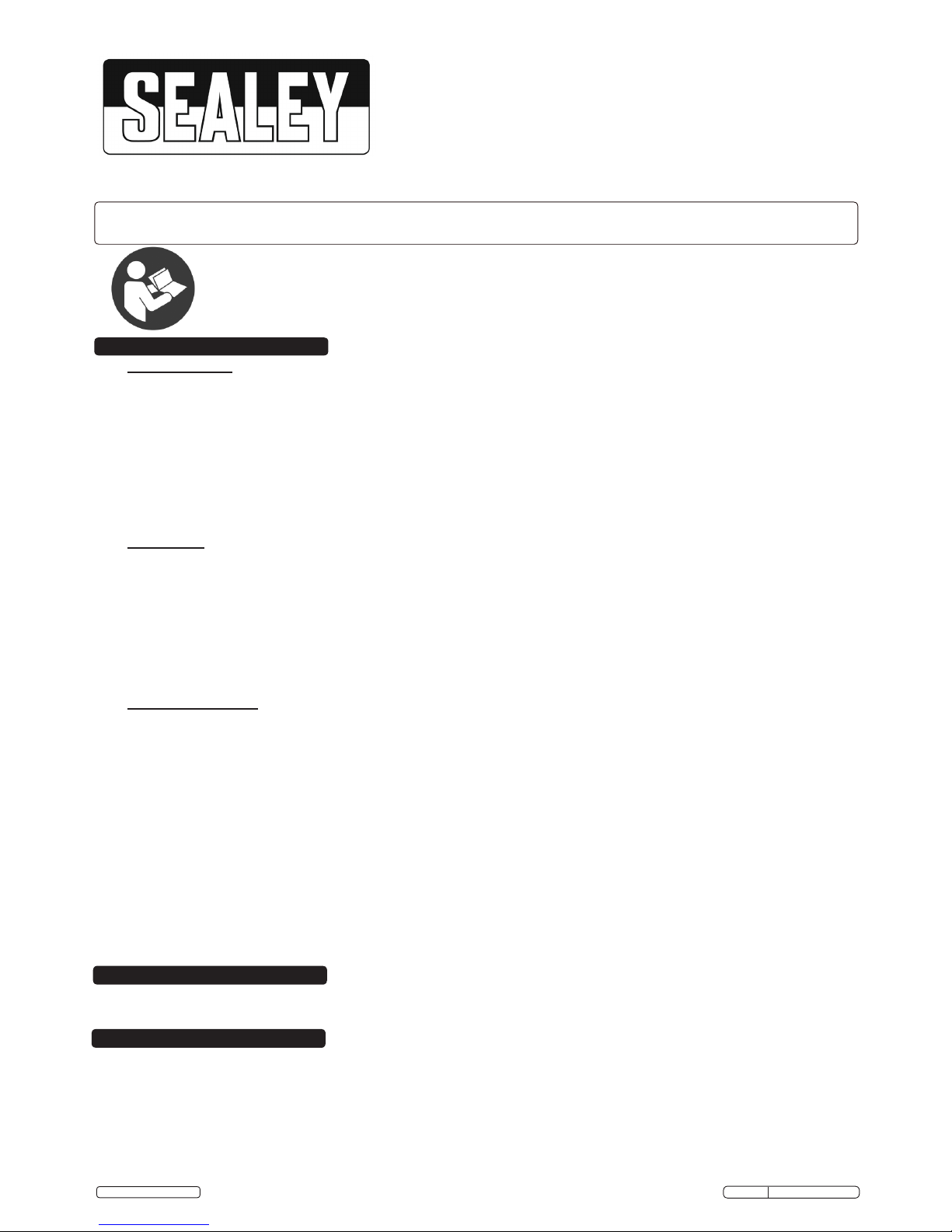
Foot operated hydraulic unit, with gauge showing force applied to the spring under compression. Supplied with three pairs of different sized
interchangeable yokes, for a wide range of vehicle applications. Fitted with plastic yoke protectors that protect the spring coating from damage
which can invalidate the vehicle manufacturer's warranty.
3. SPECIFICATION
Model No: ...................................................................RE2311
Maximum Load: ...............................................................2000kg
Upper Yoke Positions: ...............................................................7
Lower Yoke Travel: ............................................................320mm
Yoke Specification: ......................................................Size/Suitability:
Small ID-OD: ...............................................................87-129mm
Medium ID-OD: ............................................................106-165mm
Large ID-OD: ..............................................................142-202mm
Actuation:................................................................. Foot Pedal
RE2311 Issue: 1 - 10/05/16
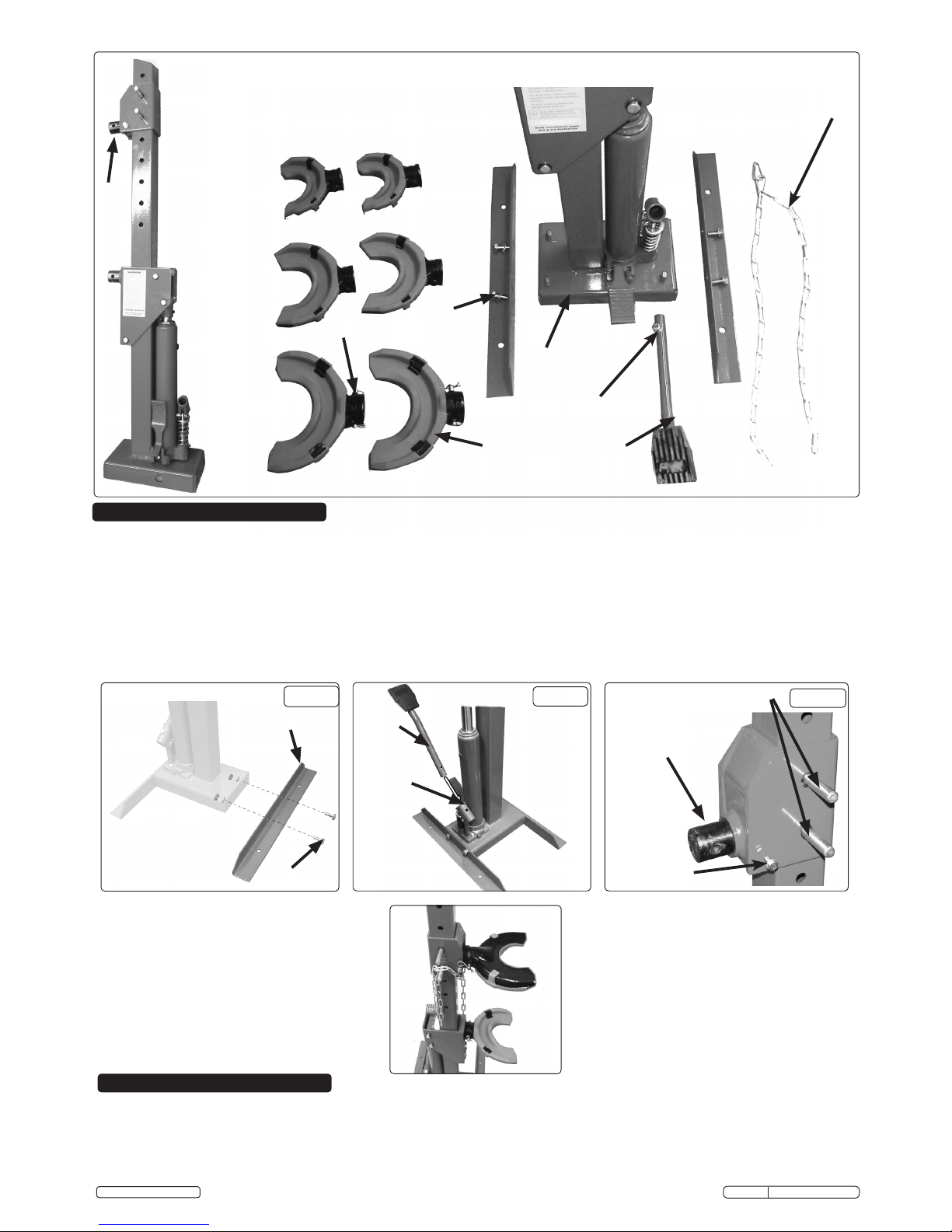
4.1. RE2311units require minimal assembly before use.
4.2. Attach the brackets item 2 to the base item 1, as illustrated in Fig.1. Be sure the brackets are fixed securely to the base as they
provide stability and will be used to secure the unit to the floor.
4.3. Assemble the main foot pedal item 3 and secure with item 10 and item 11 (Fig.2).
4.4. Three pairs of support yokes are supplied, with counter bored bosses for fitting to stub shafts shown in (Fig.3). Retain with the pin and "R"
clip item 14. The yokes are designed to be used as matched pairs and should not be mixed.
4.5. The RE2311must now be fixed securely to the floor to ensure the safety of the user. Holes are to be found in the brackets which allow the
unit to be secured by way of suitable fixings into concrete.
WARNING! Whichever method is used, ensure the unit is adequately fixed and cannot topple.
Fig.3
2
1
3
14
10,11
6
7,8,9
Contents displayed
87-129mm
106-165mm
142-202mm
12
13
Gauge
Item 1
(as
supplied)
4. ASSEMBLY
Fig.2
Fig.1
Coil compression
stub shaft (spigot)
yoke removed
Items 12 & 13
(chain anchor)
Item 2
Items 7,8,9
Items 10,11
Item 3
Removable pins
(7 height settings)
5. OPERATION
5.1. Measure the outer diameter of the spring to be compressed and select the correct set of yokes. Fit the yokes as described in section 4.4.
5.2. Operate the release valve pedal (fig.4B) and press down on the lower strut support until the piston is full retracted.
5.3. The upper yoke should bear down on the first full coil down from the top of the strut. The lower yoke should be pushing up on the first full
coil up from the bottom of the strut. Measure the distance between these coils and adjust the position of the upper strut support so that the
distance between the yokes is slightly larger than required. Ensure that the pins fixing the upper support are fully inserted and retained with
the spring clips provided. Use the foot pedal (fig.4A) to raise the lower yoke/strut support to finely adjust the distance between the yokes.
© Jack Sealey Limited
Original Language Version
RE2311 Issue: 1 - 10/05/16
2
 Loading...