

Page 1
INSTRUCTIONS FOR:
Hydraulic Press 6tonne Economy
Bench Type
Model No: YK6ECB
Thank you for purchasing a Sealey product. Manufactured to a high standard this product will, if used according to these instructions and
properly maintained, give you years of trouble free performance.
IMPORTANT: PLEASE READ THESE INSTRUCTIONS CAREFULLY. NOTE THE SAFE OPERATIONAL REQUIREMENTS, WARNINGS & CAUTIONS.
USE THIS PRODUCT CORRECTLY AND WITH CARE FOR THE PURPOSE FOR WHICH IT IS INTENDED. FAILURE TO DO SO MAY CAUSE DAMAGE
AND/OR PERSONAL INJURY AND WILL INVALIDATE THE WARRANTY. PLEASE KEEP INSTRUCTIONS SAFE FOR FUTURE USE.
1. SAFETY INSTRUCTIONS
1.1 GENERAL SAFETY
Familiarise yourself with this products application and limitations, as well as the specific potential hazards peculiar to the press.
Maintain the press in good condition (use an authorised service agent).
Replace or repair damaged parts. Use recommended parts only. Non authorised parts may be dangerous and will invalidate the warranty.
Keep the press clean for best and safest performance.
Locate the press in a suitable working area for its function, keep area clean, tidy, free from unrelated materials and ensure there is
adequate lighting.
Ensure the workpiece is correctly secured before operating the press.
WARNING! Always wear approved eye or face protection when operating the press.
Remove ill fitting clothing. Remove ties, watches, rings, loose jewellery and contain long hair.
Keep hands and body clear of the work table when operating the press.
Maintain correct balance and footing. Ensure the floor is not slippery and wear non-slip steel toe-capped shoes/boots.
Keep children and unauthorised persons away from the working area.
DO NOT operate the press if any parts are missing as this may cause failure and/or possible personal injury.
DO NOT use to compress springs or any other item that could disengage and cause a potential hazard.
DO NOT stand directly in front of the loaded press and never leave a loaded press unattended.
DO NOT use the press for any purpose other than that for which it is designed.
DO NOT make any modifications to the press.
DO NOT adjust or tamper with the safety valve.
DO NOT exceed the rated capacity of the press.
DO NOT apply off-centre loads.
DO NOT allow the workpiece or the press plates to fall from the work table.
DO NOT get the press wet or use in damp or wet locations or areas where there is condensation.
DO NOT operate the press when you are tired or under the influence of alcohol, drugs or intoxicating medication.
When not in use, release pressure from the hydraulic unit and clean the press. Stand or store the press plates in a safe location.
WARNING! Always position the press against a wall. If the press is situated in the open workshop, it is essential that a guard be
placed at the rear of the unit. This will prevent injury to bystanders in the event of the workpiece ejecting suddenly.
WARNING! The warnings, cautions and instructions in this manual cannot cover all possible conditions and situations that
may occur. It must be understood by the operator that common sense and caution are factors which cannot be built into this
product, but must be applied by the operator.
DANGER! The press is heavy. If it requires moving after assembly or for relocation, use suitable slings around the top crossbeam, or
lift direct with a forklift with the forks located under the top crossbeam. If a forklift is not available we suggest a minimum of two people are
required to lift and move the press.
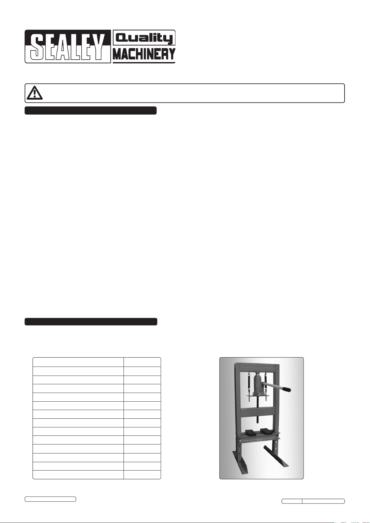
2. INTRODUCTION & SPECIFICATIONS
2.1 INTRODUCTION
Economy Range suitable for the serious enthusiast or occasional professional use. Made from high quality steel with a powder coated paint
finish to help corrosion resistance.
2.2 SPECIFICATION
Model: YK6ECB
Bench or Floor Mounting Bench
Type: Hydraulic
Capacity: 6tonne
Ram Stroke: 125mm
Ram Ø: 20mm
Maximum Height - Ram to Table: 245mm
Minimum Height - Ram to Table: 0mm
Table Aperture: 65mm
Work Table Depth: 145mm
Work Table Width: 340mm
Overall Height: 935mm
Gauge Included: No
Weight: 26.4kg
© Jack Sealey Limited 2012
Original Language Version
YK6ECB Issue No: 1 - 16/07/12
Page 2
3. ASSEMBLY
3.1 PRESS ASSEMBLY
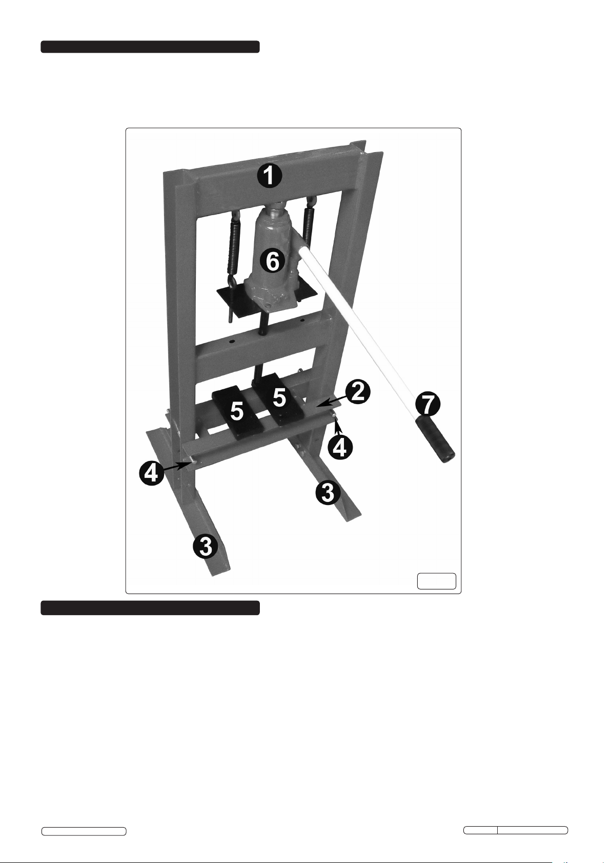
3.1.1 Attach slings around the top crossbeam, using a suitable hoist or gantry lift the main frame (fig.1.1) out of the transportation packing
into an upright position. If a hoist or gantry is not available, ensure a minimum of two people lift the press from the packing.
3.1.2 Keep the main frame (fig.1.1) held safely upright. DO NOT allow to fall. Attach base sections (fig.1.3) to the left and right hand posts.
Only fully tighten the securing nuts and bolts when the base sections (fig.1.3) are square to the main frame (fig.1.1).
3.1.3 Insert the work table (fig.1.2) in position in the main frame (fig.1.1) and support with work table pins (fig.1.4).
g.1
4. INSTALLATION & OPERATING
WARNING! Before use, ensure that you have read, understood and apply Section 1 safety instructions.
4.1 INSTALLATION
4.1.1 Securely attach the press to a flat, firm, level surface taking into account clearance for workpieces.
DANGER! The press is heavy. If it requires moving after assembly or for relocation, use suitable slings around the top crossbeam,
or lift direct with a forklift with the forks located under the top crossbeam, or ensure a minimum of two people lift the press.
4.2 PURGE HYDRAULIC SYSTEM
4.2.1 Before operating the press, the hydraulic system (fig.1.6) may require purging in order to eliminate any air that may have built up during
transit.
4.2.2 Open the control valve (fig.2) by turning anti-clockwise and pump the handle (fig.1.7) 20 times.
4.2.3 Should the system malfunction at any time, repeating this procedure may resolve the problem.
DANGER! The press is purpose designed to withstand greater loads than the hydraulic unit can develop. For safety reasons, always
ensure the workpiece is secured on the work table to ensure loads that flex will not suddenly “give” causing danger to operator or
damage to component. Ensure you have read and understood Section 1 safety instructions.
4.3 SETTING THE WORK TABLE HEIGHT
4.3.1 To set the work table (fig.1.2) at the desired height it is advisable to obtain assistance. Remove the press plates (fig.1.5) from the work
table (fig.1.2) then remove the pins (fig.1.4). Position the work table (fig.1.2) at the required operating height, insert the pins (fig.1.4)
into the appropriate holes in the main frame (fig.1.1).
4.4 OPERATING
4.4.1 Place the press plates (fig.1.5) onto the work table (fig.1.2), then place workpiece onto the press plates (fig.1.5) and align as required.
© Jack Sealey Limited 2012
Original Language Version
YK6ECB Issue No: 1 - 16/07/12
Page 3

Note: Care must be taken to ensure that the press plates (fig.1.5) do not fall from the work table (fig.1.2). If necessary hold the
configuration in position with clamps.
4.4.2 Fit handle (fig.1.7) over control valve and rotate clockwise to close valve (fig.2).
4.4.3 Place handle (fig.1.7) into handle sleeve on the hydraulic system (fig.1.6) and pump handle (fig.1.7) to apply load to the workpiece.
WARNING! DO NOT apply off-centre loads.
4.4.4 When work is done, stop pumping the handle (fig.1.7). Slowly and carefully release load from workpiece by fitting the handle (fig.1.7)
over the control valve and turning anti-clockwise in small increments (fig.2).
Note: Always keep the hydraulic unit fully retracted after use to avoid ram corrosion.
4.4.5 Once the hydraulic unit has been fully retracted, remove the workpiece from the press.
g.2
5. MAINTENANCE
Note: Maintenance and repair must only be carried out by a qualified person. Contact your Sealey dealer for details.
5.1 Always keep the press clean, dry and lubricate all moving parts at regular intervals.
5.2 When not in use always store in a dry location with the hydraulic unit (fig.1.6) fully retracted.
5.3 Should you need to check or replace oil, ensure the hydraulic unit (fig.1.6) is fully retracted. Remove the oil reservoir filler plug and top
up using Sealey hydraulic jack oil (Sealey Part No's: HJO500MLS/HJO5LS). DO NOT use brake fluid. After filling, purge the system
as described in Section 4.2. to remove any air.
To obtain a parts list and diagram please log on to www.sealey.co.uk, email sales@sealey.co.uk or phone 01284 757500
Parts support is available for this product.
IMPORTANT: NO RESPONSIBILITY IS ACCEPTED FOR INCORRECT USE OF THE PRESS.
Hydraulic products are only repaired by local service agents. We have service/repair agents in all parts of the UK.
DO NOT RETURN PRODUCT TO US. Please telephone us on 01284 757500 to obtain the address and phone number of your local agent.
If product is under guarantee please contact your dealer.
De-commissioning Product
Should the product become completely unserviceable and require disposal, draw off the oil into an approved container and dispose of the
product and the oil according to local regulations.
NOTE: It is our policy to continually improve products and as such we reserve the right to alter data, specifications and component parts without prior notice.
IMPORTANT: No liability is accepted for incorrect use of product.
WARRANTY: Guarantee is 12 months from purchase date, proof of which will be required for any claim.
INFORMATION: For a copy of our latest catalogue and promotions call us on 01284 757525 and leave your full name and address, including postcode.
© Jack Sealey Limited 2012
Sole UK Distributor, Sealey Group,
Kempson Way, Suffolk Business Park,
Bury St. Edmunds, Suffolk,
IP32 7AR
Original Language Version
01284 757500
01284 703534
www.sealey.co.uk
Web
sales@sealey.co.uk
email
YK6ECB Issue No: 1 - 16/07/12
 Loading...