

Sealey Quality MACHINERY YK4B Quick Start Manual
Hydraulic Press 4tonne Bench
Type without Gauge
Model No: YK4B
Thank you for purchasing a Sealey product. Manufactured to a high standard this product will, if used according to these instructions and
properly maintained, give you years of trouble free performance.
IMPORTANT: PLEASE READ THESE INSTRUCTIONS CAREFULLY. NOTE THE SAFE OPERATIONAL REQUIREMENTS, WARNINGS & CAUTIONS.
USE THIS PRODUCT CORRECTLY AND WITH CARE FOR THE PURPOSE FOR WHICH IT IS INTENDED. FAILURE TO DO SO MAY CAUSE DAMAGE
AND/OR PERSONAL INJURY AND WILL INVALIDATE THE WARRANTY. PLEASE KEEP INSTRUCTIONS SAFE FOR FUTURE USE.
1. SAFETY INSTRUCTIONS
1.1 GENERAL SAFETY
Familiarise yourself with this products application and limitations, as well as the specific potential hazards peculiar to the press.
Maintain the press in good condition (use an authorised service agent).
Replace or repair damaged parts. Use recommended parts only. Non authorised parts may be dangerous and will invalidate the warranty.
Keep the press clean for best and safest performance.
Locate the press in a suitable working area for its function, keep area clean, tidy, free from unrelated materials and ensure there is
adequate lighting.
Ensure the workpiece is correctly secured before operating the press.
WARNING! Always wear approved eye or face protection when operating the press.
Remove ill fitting clothing. Remove ties, watches, rings, loose jewellery and contain long hair.
Keep hands and body clear of the work table when operating the press.
Maintain correct balance and footing. Ensure the floor is not slippery and wear non-slip steel toe-capped shoes/boots.
Keep children and unauthorised persons away from the working area.
DO NOT operate the press if any parts are missing as this may cause failure and/or possible personal injury.
DO NOT use to compress springs or any other item that could disengage and cause a potential hazard.
DO NOT stand directly in front of the loaded press and never leave a loaded press unattended.
DO NOT use the press for any purpose other than that for which it is designed.
DO NOT make any modifications to the press.
DO NOT adjust or tamper with the safety valve.
DO NOT exceed the rated capacity of the press.
DO NOT apply off-centre loads.
DO NOT allow the workpiece or the press plates to fall from the work table.
DO NOT get the press wet or use in damp or wet locations or areas where there is condensation.
DO NOT operate the press when you are tired or under the influence of alcohol, drugs or intoxicating medication.
When not in use, release pressure from the hydraulic unit and clean the press. Stand or store the anvil "V" blocks in a safe location.
WARNING! Always position the press against a wall. If the press is situated in the open workshop, it is essential that a guard be
placed at the rear of the unit. This will prevent injury to bystanders in the event of the workpiece ejecting suddenly.
WARNING! The warnings, cautions and instructions in this manual cannot cover all possible conditions and situations that
may occur. It must be understood by the operator that common sense and caution are factors which cannot be built into this
product, but must be applied by the operator.
DANGER! When lifting or moving the assembled press, it is recommended that it is transported by two people.
2. INTRODUCTION & SPECIFICATIONS
2.1 INTRODUCTION
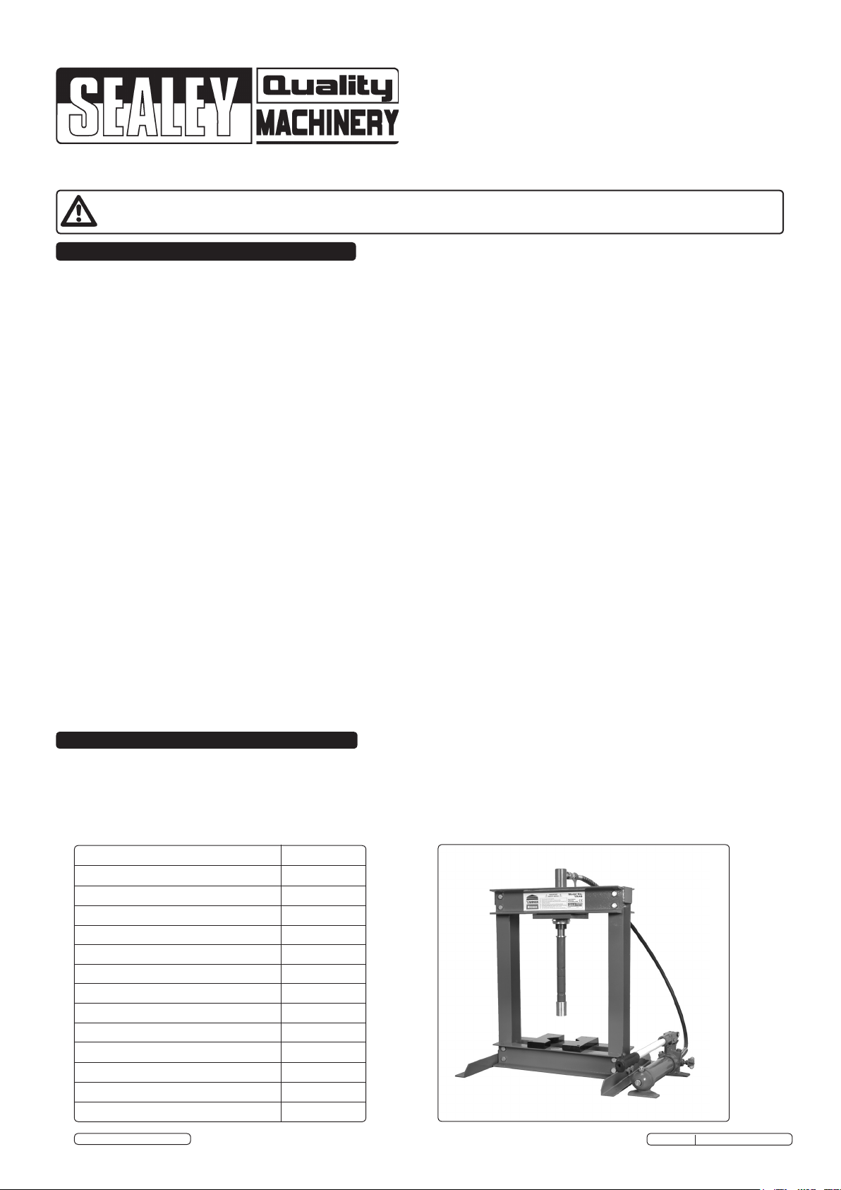
Economic versatile engineered press, suitable for the serious enthusiast and the occasional professional user. Made from cold rolled
steel and fabricated mild steel sections, with a powder coated paint finish. Bolted construction.
2.2 SPECIFICATIONS:-
Model: YK4B
Bench or Floor Mounting Bench
Type: Hydraulic
Capacity: 4tonne
Ram Stroke: 120mm
Ram Ø: 20mm
Maximum Height - Ram to Table: 330mm
Minimum Height - Ram to Table: 115mm
Table Aperture: 70mm
Work Table Depth: 135mm
Work Table Width: 335mm
Overall Height: 660mm
Gauge Included: No
Weight: 31kg
© Jack Sealey Limited 2012
Original Language Version
YK4B Issue No: 1 - 01/08/12
3. ASSEMBLY
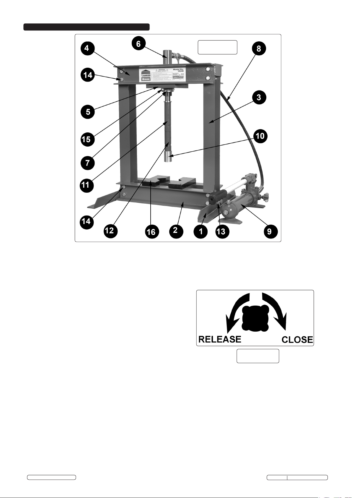
Fig 1
3.1 ASSEMBLY
3.1.1 Unpack product and check contents against list below. Should there be any damaged or missing parts contact your supplier
immediately. Refer to the appropriate parts diagram as a guide to assembly, read all notes prior to assembly.
3.1.2 Contents:
Item No. Description Qty
1 Feet (RSA) 2
2 Base Channel (RSC) 2
3 Vertical (Fabrication) 2
4 Top Channel (RSC) 2
5 Ram Mtg Plate 1
6 Ram (sub assembly) 1
7 Ram Collar 1
8 Hydraulic Hose 1
9 Pump c/w lever (loose) 1
10 Ram Mandrel 1
11 Spacer Short c/w snap ring 1
12 Spacer Long c/w snap ring 1
13 M12 Screws c/w washers 4
14 M10 Screws c/w washers 16
15 M8 Screws c/w washers 2
16 Anvil "V" Blocks (loose) 2
3.1.3 Identify and lay out parts. On a firm level surface, assemble main frame items (1 to5) with associated fixings, items (13 - 15).
DO NOT fully tighten fixings at this assembly stage.
3.1.4 Ensure vertical members item 3 are vertical in both planes and bottom channels item 2 are horizontal; tighten fixings in feet item 1.
Ensure top channels are horizontal in both planes and tighten fixings in vertical members item 3 and item 5. Fit remaining items.
3.1.5 Securely attach the press to a flat, firm, level surface taking into account clearance for working pieces. Should you wish to mount
a bench press on a workbench or surface, ensure the bench is flat and level and is strong enough to support the press and any work
piece during operation. Similarly attach the hand lever pump assembly securely in desired sound location.
3.1.6 Once installed, screw the pump lever into the pump arm.
Fig 2
WARNING! Observe ‘safe handling practices’ by using two people to position the press.
3.1.7 Place v-blocks on work table ready for use. Take care to ensure the v-blocks do not fall from the work table. Select either Item 11 or 12
or both depending upon press clear opening height required. Spacers coupled simply and held by snap ring in spacer spigot.
3.1.8 Before operating the press, purge the hydraulic system in order to eliminate any air that may have built up during transit. Open the
release valve (Fig 2) and pump the handle several times (suggested 20 times). Should the system malfunction at any time, repeating
this process may resolve the problem. If not refer to Maintenance heading 5.
© Jack Sealey Limited 2012
Original Language Version
YK4B Issue No: 1 - 01/08/12
 Loading...