

Page 1
INSTRUCTIONS FOR:
10” TABLE SAW WITH STAND &
EXTENSION WINGS
MODEL No:
Thank you for purchasing a Sealey product. Manufactured to a high standard this product will, if used according to these instructions
and properly maintained, give you years of trouble free performance.
IMPORTANT: PLEASE READ THESE INSTRUCTIONS CAREFULLY. NOTE THE SAFE OPERATIONAL REQUIREMENTS, WARNINGS AND
CAUTIONS. USE THIS PRODUCT CORRECTLY AND WITH CARE FOR THE PURPOSE FOR WHICH IT IS INTENDED. FAILURE TO DO SO MAY
CAUSE DAMAGE AND/OR PERSONAL INJURY AND WILL INVALIDATE THE WARRANTY. PLEASE KEEP INSTRUCTIONS SAFE FOR FUTURE USE.
TS10SEW
1. SAFETY INSTRUCTIONS
1.1. ELECTRICAL SAFETY
WARNING! It is the user ’s responsibility to read, understand and comply with the following:
You must check all electrical equipment and appliances, before using, to ensure that they are safe. You must inspect power supply leads,
plugs and all electrical connections for wear and damage. You must ensure the risk of electric shock is minimised by the installation of
appropriate safety devices. An RCCB (Residual Current Circuit Breaker) should be incorporated in the main distribution board. We also
recommend that an RCD (Residual Current Device) is used with all electrical products. It is particularly important to use an RCD with portable
products that are plugged into an electrical supply not protected by an RCCB. If in doubt consult a qualified electrician. You may obtain a Residual
Current Device by contacting your Sealey dealer. You must also read and understand the following instructions concerning electrical safety.
1.1.1. The Electricity At Work Act 1989 requires all portable electrical appliances, if used on business premises, to be tested by
a qualified electrician, using a Portable Appliance Tester (PAT), at least once a year.
1.1.2. The Health & Safety at Work Act 1974 makes owners of electrical appliances responsible for the safe condition of the appliance
and the safety of the appliance operator. If in any doubt about electrical safety, contact a qualified electrician.
1.1.3. Ensure the insulation on all cables and the product itself is safe before connecting to the mains power supply. See 1.1.1. & 1.1.2.
above and use a Portable Appliance Tester (PAT).
1.1.4. Ensure that cables are always protected against short circuit and overload.
1.1.5. Regularly inspect power supply leads, plugs for wear and damage and power connections, to
ensure that none is loose.
1.1.6. Important: Ensure the voltage marked on the product is the same as the electrical power supply
to be used, and check that plugs are fitted with the correct capacity fuse. A 13 amp plug may
require a fuse smaller than 13 amps for certain products, see fuse rating at right.
1.1.7. DO NOT pull or carry the appliance by its power supply lead.
1.1.8. DO NOT pull the plug from the socket by the power cable.
1.1.9. DO NOT use worn or damage leads, plugs or connections. Immediately replace or have
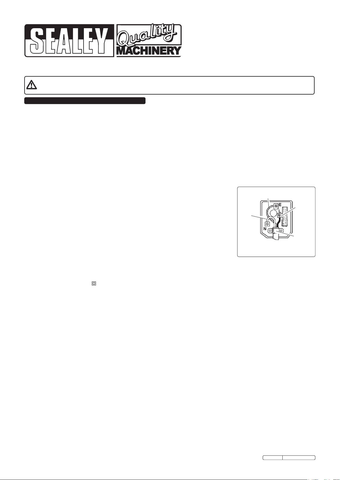
repaired by a qualified electrician. A U.K. 3 pin plug with ASTA/BS approval is fitted. In case of
damage, cut it off and fit a new plug according to the following instructions (discard old plug safely).
(UK only - see diagram at right). Ensure the unit is correctly wired via a three-pin plug.
a) Connect the yellow/green earth wire to the earth terminal ‘E’.
b) Connect the brown live wire to live terminal ‘L’.
c) Connect the blue neutral wire to the neutral terminal ‘N’.
d) After wiring, check that there are no bare wires, that all wires have been correctly connected, that the cable outer
insulation extends beyond the cable restraint and that the restraint is tight.
Double insulated products are fitted with live (BROWN) and neutral (BLUE) wires only. Double insulated products are always
marked with this symbol . To re-wire, connect the brown & blue wires as indicated above. DO NOT connect the brown or blue
to the earth terminal.
1.1.10. Some products require more than a 13 amp electrical supply. In such a case, NO plug will be fitted. You must contact a qualified
electrician to ensure a 30 amp fused supply is available. We recommend you discuss the installation of a industrial round pin plug and
socket with your electrician.
1.1.11. Cable extension reels. When a cable extension reel is used it should be fully unwound before connection. A cable reel with an RCD
fitted is recommended since any product which is plugged into the cable reel will be protected. The section of the cores of the cable
is important and should be at least 1.5mm2, but to be absolutely sure that the capacity of the cable reel is suitable for this product and
for others that may be used in the other output sockets, we recommend the use of 2.5mm² section cable.
1.2. GENERAL SAFETY
Familiarise yourself with the applications, limitations and potential hazards of the saw.
WARNING! Disconnect the saw from the mains power before changing accessories, servicing or performing any maintenance.
The machine must only be serviced by a qualified person or service agent. Contact your Sealey dealer for information.
Select a work area suitable for the saw and keep the area clean, tidy and free from unrelated materials. Ensure that there is adequate lighting.
Stand the saw on a stable floor strong enough to take the weight of the machine and workpiece.
Wood dust can be harmful to health by inhalation and skin contact and concentrations of small dust particles in the air can form an
explosive mixture. Ensure that there is adequate ventilation and that the saw is attached to a dust-extraction unit.
Maintain the saw in good condition, check moving parts alignment regularly. Keep saw blades clean and sharp. ,
Replace or repair damaged parts. Use recommended parts only. Unauthorised parts may be dangerous and will invalidate the warranty.
WARNING! Keep all guards in place and in good working order. Check regularly for damaged parts.
A guard, or any other part, that is damaged must be repaired or replaced before the saw is next used. The safety guard is a
mandatory fitting where the saw is used on premises covered by the Health & Safety at Work Act.
Before commencing work, ensure that the saw blade is set to cut in the correct direction, securely fastened, sharp and is compatible
with the machine, spindle speed and the material to be cut. Never use a saw blade if damaged, bent or warped. Use only
recommended saw blades.
Remove adjusting keys and wrenches from the machine and the vicinity before switching on.
Machine operators must have received sufficient training and instructions relating to the dangers associated with the machine, the
precautions to be observed and those requirements of the Wood Working Machines Regulations which apply. Inexperienced
operators must be under the adequate supervision of a person who has a thorough knowledge and experience of the machine and the
required guards.
DO NOT operate the saw if any parts are damaged or missing as this may cause product failure and/or personal injury.
Original Language Version
Blue
Neutral
Wire
FUSE RATING 13AMP
Yellow & Green
Earth Wire
Brown
Live
Wire
Cable
Restraint
TS10SEW Issue: 2 - 12/01/10
Page 2
DO NOT operate the saw when you are tired or under the influence of alcohol, drugs or intoxicating medication.
When not in use, switch off the saw and unplug from the power supply.
WARNING! Wear approved safety eye protection, ear defenders and respiratory protection.
Remove ill fitting clothing. Remove ties, watches, rings and other loose jewellery and contain long hair.
Keep hands and body clear of the blade when operating the saw.
Maintain correct balance and footing. Ensure the floor is not slippery and wear non-slip shoes.
Keep children and unauthorised persons away from the work area.
Avoid unintentional starting and never leave the saw operating unattended.
DO NOT use the saw for a task it is not designed to perform and ensure that operators are trained to use the saw.
DO NOT get the saw wet or use in damp or wet locations or areas where there is condensation.
DO NOT use the saw where there are flammable liquids, solids or gases such as paint solvents and including waste cleaning rags etc.
1.3. SPECIFIC SAW SAFETY RULES
Connect to a suitable extraction system. Failure to do so will result in the build-up of sawdust which will become a fire hazard.
Keep riving knife and blade guard in place and operational, and replace table insert when worn.
Ensure that the saw blade is suitable for the material to be cut.
WARNING! Before each use, check that the saw blade is secure and not worn or damaged.
Use the blade guard for all “through-sawing” operations. Through-sawing operations are those where the blade cuts completely through the
workpiece as in ripping or cross-cutting.
Check workpiece to ensure that there are no nails or other items which may foul the saw blade.
Hold the work firmly against the fence bar.
Only feed the workpiece into the blade against the rotation of the blade.
Avoid subjecting the saw blade to excessive strain - never force the workpiece. Maintain a controlled, steady progression.
Should the saw blade jam, switch the power off immediately to prevent damage to the motor.
To avoid “kickback” (when a workpiece is violently thrown back towards the operator) implement the following:
a) Keep the blade sharp.
b) Keep the fence parallel to the saw blade.
c) DO NOT release the workpiece before it is pushed all the way past the saw blade.
d) DO NOT rip work that is twisted or warped or does not have a straight edge to guide along the fence.
Use a push stick for ripping narrow workpieces.
Provide adequate support to the rear and sides of the saw table for long or wide workpieces.
DO NOT use your hands alone (“free-hand”) to guide the workpiece. Hold work firmly against the fence bar to guide work through the saw.
DO NOT place yourself in an awkward operating position where a slip could cause your hand to move into the blade.
DO NOT stand, or have any part of your body, in line with the path of the saw blade.
DO NOT use the fence as a cut-off gauge when cross-cutting.
DO NOT hold what will become the off-cut (the waste part of the workpiece).
WARNING! DO NOT reach behind or over the saw blade.
WARNING! DO NOT attempt to free a jammed saw blade without first switching off and removing the plug from the mains power supply.
DO NOT cut metals or substances that may produce toxic dust. Saw must only be used to cut wood or wood derived materials.
DO NOT attempt to cut round section wood.
DO NOT use solvents to clean plastic parts. Use a soft damp cloth only.
Store saw and blades in a safe, dry childproof location.
2. INTRODUCTION & DESCRIPTION
Large die cast aluminium table with two side
and one rear extension tables. Adjustable
height and tilting blade up to 45°. Fitted with
no-volt release safety switch for user safety.
Includes quick-lock rip-fence, mitre gauge, dust
extraction port, push stick and metal stand.
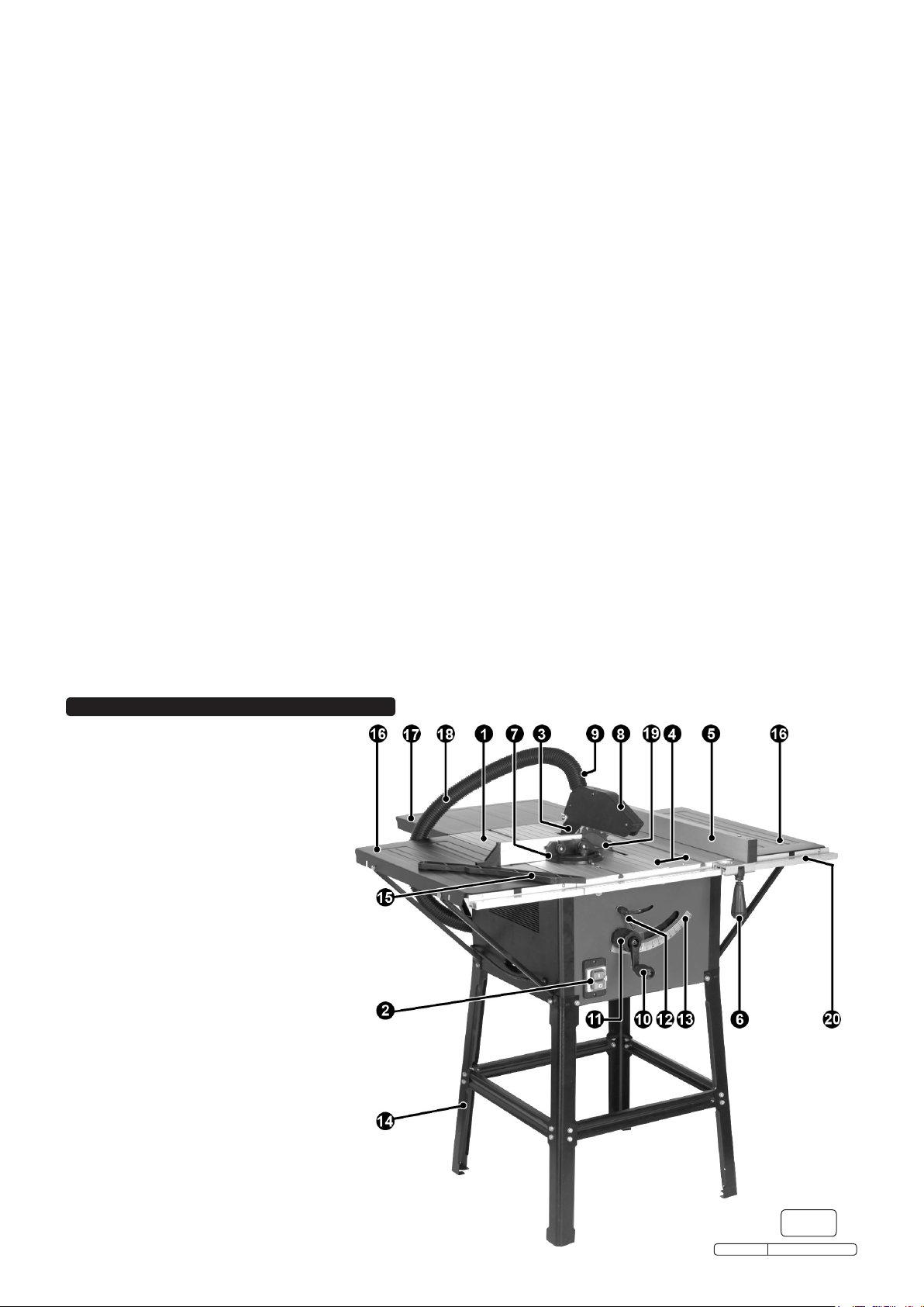
MAIN PARTS GUIDE
1 Saw table top
2 “No-Volt” On/Off switch
3 Riving knife
4 Removable table top section
5 Rip fence
6 Rip fence locking lever
7 Mitre gauge
8 Blade guard
9 Dust extraction duct
10 Blade depth adjustment handle
11 Blade bevel adjustment wheel
12 Blade bevel locking knob
13 Bevel scale
14 Metal stand
15 Push stick
16 Side table extensions (x2)
17 Rear table extension
18 Flexible dust extractor hose
19 Saw blade
20 Rip fence measurement guide
Original Language Version
g.1
TS10SEW Issue: 2 - 12/01/10
Page 3

3. SPECIFICATION
Motor ......................... 1500W - 230V
Speed .............................. 5700rpm
Saw Blade Diameter...................Ø254mm
Saw Blade Arbor.......................Ø20mm
Max. Depth of 90° Cut ................... 75mm
Max. Depth of 45° Cut ................... 60mm
Main Table ...................... 440 x 625mm
Side Extension Sizes (x2): .......... 245 x 585mm
Rear Extension Size: .............. 320 x 435mm
Table with Extensions .............. 915 x 940mm
Dust Extraction Port (Taper)..............Ø40mm
4. ASSEMBLY
4.1 The unit is best assembled upside down on a smooth and flat surface. Ensure that the saw blade is fully retracted under the work
table before turning the unit over.
4.2 Assemble a leg to each corner of the unit using two 12mm long bolts and two small washers. Ensure that the two rectangular holes at
the top of each leg are aligned with the moulded rectangular spigots on each corner of the unit. See A & B in fig.2. Do not fully tighten
the bolts at this stage.
4.3 When all four legs are in place assemble the cross struts as shown in fig.3 using two 12mm long bolts, two nuts and two small
washers at each end of the strut. Two of the struts are 20mm longer than the other pair and should be assembled to the legs above
the side of the unit that has the on/off switch and the opposite side above the dust extractor. Each strut has a narrow returned edge
and a wide returned edge. The wide returned edge of each strut should always be nearest to the underside of the unit. Note that the
ends of the cross struts are angled to match the outward angling of the legs. All fixings should be hand tight at this stage.
g.2
4.4 At one end of each side table is an aluminium guide track which will form an extension to the main rip fence guide track on the front of
the main unit. Two joining plates are provided to ensure that the three sections of the track are properly aligned. Place a large washer
over a 12mm bolt and screw it into each joining plate as shown in fig.4. Turn the two side tables upside down and slide the joining
plates into the slots at the end of the track as shown in fig.4. Hand tighten the bolts so that the plates are drawn up under the tracks as
shown in fig.5 ensuring that the washer rests on the outside face of the guides.
g.4
g.3
g.5
4.5 Place the two side tables upside down onto the floor beside the main unit as shown in fig.6 and slide them up to the main unit so that
the joining plates slide into the aluminium rip fence guide at either end. Place another large washer over a 12mm bolt and screw into
place on the rip fence guide as shown in fig.7. Using the four cheese headed screws provided attach each side table to the main table
using two screws on each side. Tighten these screws and the joining plate bolts.
4.6 Identify the four shorter table stays and attach two to each side table. The two returned edges of the stays should be facing the
underside of the side tables. Each stay shares one of the leg fixings at each corner. Remove the leg fixing that lines up with the
appropriate fixing on the far edge of each side table and hold the stay in position whilst replacing the bolt. Use a 12mm bolt, washer
and nut to fix the stay to the edge of the side table. Repeat the process for all four stays.
4.7 Take the rear extension table and place it upside down on the floor at the back edge of the main work table. One side of the table has
slots which should be lined up with the threaded holes in the back of the main table and the other side has two holes for mounting the
stays. Use two 12mm bolts to fix the extension to the main table. Attach the two longer stays to the rear extension table in the same
Original Language Version
TS10SEW Issue: 2 - 12/01/10
Page 4

g.6
way that the side stays were attached. Now tighten all leg fixings, cross braces and stays.
4.8 Turn the assembly upright and check that the main table and extensions form a flat and step free surface.
4.9 Raise the blade and riving knife by turning the blade depth adjustment handle (10) clockwise.
4.10 Remove the butterfly nut, bolt and washer from the blade guard and slide the guard over the riving knife until the hole in the knife
aligns with the hole in the guard. Slide the bolt through both the knife and guard and replace the washer and butterfly nut.
4.11 Take the mitre gauge and slide its metal bar into one of the slots on either side of the blade. Hold the mitre face extension bar in front
of the mitre gauge allowing the two sliding bolts at the back to drop into the slots in the mitre face. Tighten the thumb wheels.
4.12 Attach the flexible dust extraction hose (18) to the outlet on the blade guard (9). Attach the other end to the dust extraction inlet on the
back of the saw.
4.13 Lay the measurement scales provided, into the shallow recess on the upper face of the rip fence guide. Fix in place with the 6 small
self tapping screws provided. Do not fully tighten so that the measurement scale can slide within the bounds of the fixing slots.
4.14 Take the rip fence (5) and lift the locking handle to the horizontal position. Place the rip fence down over the rip fence guide
so that it rests flat against the left hand side of the saw blade and move the handle downwards to lock it in position. Look through the
sight glass and adjust the position of the measurement scale so that zero is aligned with the sight glass mark. Tighten the three fixing
screws that hold the left hand measurement scale. Release the rip fence and place it flat against the right hand side of the blade.
Repeat the alignment process for the right hand measurement scale and tighten the fixing screws. Slide the rip fence away from the
blade.
g.7
5. OPERATION
The saw is fitted with a “No-Volt” On/Off switch. If the power supply is interrupted whilst the saw is on, the saw has to be switched back on
again when the power supply is restored. To switch ON press the green “I” switch. To switch OFF press the red button.
Caution: Switch off the machine and unplug from the power supply before carrying out any adjustments, maintenance work or blade changes.
5.1. Fitting and removing the saw blade guard and dust extractor
5.1.1. To remove the saw blade guard (8), unscrew the wing nut and remove the bolt, then lift off the guard.
5.1.2. To replace it, slide it over the riving knife aligning the slot in the guard with the knife (3), and align it so that the holes in both the guard
and the riving knife are aligned.
5.1.3. Insert the bolt and fit the wing nut.
5.1.4. Tighten the wing nut sufficiently so that the
guard rests on the saw table top (1) but will
lift easily when a workpiece is pushed
towards the blade and also returns to rest
on the saw table after the workpiece has
been removed.
5.1.5. A suitable vacuum extraction system should
be connected to the outlet of the vacuum
extraction adaptor port at the rear of the table.
5.1.6. Connect one end of the flexible hose (18) to
the dust extractor duct (9) and the other end
to the vacuum extraction adaptor port at the
rear of the table.
5.2. Adjusting the rip fence
5.2.1. The rip fence can be fitted to either side of
the table top (1)
5.2.2. Lift the rip fence locking lever (6) and slide
the fence to the required position.
5.2.3. Use the scale (20) on the front of the table
top to set the rip fence so that the work
piece is sawn to the required width.
5.2.4. Push down the rip fence locking lever (6) to
clamp the rip fence in position.
5.3. Adjusting the cutting depth
5.3.1. Set the saw blade to the required cutting
depth by turning the blade depth adjustment
wheel (10).
5.3.2. Turning the wheel anti-clockwise increases
the cutting depth, and clockwise decreases it.
Original Language Version
g.1repeated
TS10SEW Issue: 2 - 12/01/10
Page 5

5.4. Adjusting the riving knife
5.4.1. Set the saw blade to maximum cutting depth, move it to the 0° position and
lock it in place with the blade bevel locking knob (12).
5.4.2. Remove the saw blade guard (see 5.1.1).
5.4.3. Remove the two screws securing the removable table top section (4) and
take out the section.
5.4.4. Slacken the bolt holding the riving knife (3) in place.
5.4.5. Raise or lower the riving knife as appropriate so that the distance between
the saw table and the top edge of the riving knife is about 20 mm more than
the height of any workpiece that is to be cut.
5.4.6. The distance between the riving knife and the saw blade should be 3 to 8 mm.
5.4.7. Re-tighten the bolt and refit and fix in place the table top section and replace
the saw blade guard.
5.5. Making longitudinal cuts
Important: After each new adjustment it is advisable to carry out a trial cut in order to check the set dimensions. After switching on the
saw, wait for the blade to reach its maximum speed of rotation before commencing a cut. Take extra care when starting a cut.
5.5.1. Longitudinal cuts involve cutting through a workpiece along its full length.
5.5.2. One edge of the workpiece is pressed against the rip fence while its flat side rests on the table top.
5.5.3. The saw blade guard must always be in place and be adjusted to cover the workpiece.
5.5.4. When making longitudinal cuts, always stand to one side of the cutting line.
5.5.5. Set the rip fence to suit the required width using the measuring scales at the front of the table.
5.5.6. Switch on the saw.
5.5.7. With fingers together, place hands flat on the workpiece and push it along the fence into the saw blade.
5.5.8. Guide the workpiece at the side with your left hand only as far as the front edge of the guard hood.
5.5.9. Always push the workpiece through to the end of the riving knife.
5.5.10. Leave the offcuts on the saw table until the saw blade has stopped.
5.5.11. Secure a long workpiece against sagging at the end of the cutting operation (e.g. with a roller table or similar device).
5.5.12. Use the push stick for guiding the workpiece if hand gets to within 125 mm (5in) of the saw blade.
g.9
5.6. Cutting a narrow workpiece
5.6.1. Longitudinal cuts in a workpiece smaller than 125mm (5in) width must always be made with the help of the push stick.
5.6.2. Longitudinal cuts in an extremely narrow workpiece with a width of 30mm (1¼in) or less must always be made with the help of a
push block. A push block can be made from an offcut piece of wood.
5.7. Adjusting the bevel cutting angle stops
5.7.1. Set the saw blade to maximum cutting depth by rotating the blade depth adjustment wheel (10) anticlockwise as far as possible.
5.7.2. Slacken the blade bevel locking knob (12).
5.7.3. Rotate the blade bevel adjustment knob (11) anticlockwise as far as possible until the arrow points to 0°.
5.7.4. Tighten the blade bevel locking knob (12). Place a square between the saw table and the saw blade.
5.7.5. If the angle is not exactly 90°, loosen the adjusting bolt slightly, reposition and then re-tighten it. The adjusting bolt is located under the
front of the table top, just above the blade bevel locking knob on the left hand side.
5.7.6. It may be necessary to slacken the blade bevel locking knob (12) again and adjust the blade bevel adjustment knob (11) again, in
order to move the saw blade a little further to the left and re-check the angle is correct.
5.7.7. Now turn the blade bevel adjustment knob (11) to the right until the arrow points to 45°.
5.7.8. Tighten the blade bevel locking knob again.
5.7.9. Place a 45° angle between the saw table and the saw blade.
5.7.10. If the angle is not exactly 45° you can adjust it with the adjusting bolt in a similar way to the procedure described above. The adjusting
bolt is located under the front of the table top, just above the blade bevel locking knob on the right hand side.
Important: Be sure to secure the selected angle setting by tightening the blade bevel locking knob (12) before you start to use the saw.
5.8. Making bevel cuts
5.8.1. Always use the fence when cutting bevels.
5.8.2. Set the saw blade to the required angle by slackening the blade bevel locking knob (12) and then turn the blade bevel adjustment
wheel (11) until the indicator points to the required angle on the bevel scale (13). Securely tighten the blade bevel locking knob (12).
5.8.3. Set the fence to suit the width of the workpiece.
5.8.4. Carry out the cut in accordance with the workpiece width.
5.8.5. Use the push stick for guiding the workpiece if hand gets to within 125 mm (5in) of the saw blade.
5.9. Using the mitre gauge and making cross cuts
5.9.1. Slide the mitre gauge (7) into one of the two slots on the saw table top (1).
5.9.2. Slacken the knurled knob on the mitre gauge, adjust mitre gauge until the arrow points to the required angle, tighten the knurled knob.
5.9.3. Press the workpiece firmly against the mitre gauge and switch on the saw.
5.9.4. Push the mitre gauge and the workpiece together towards the saw blade in order to make the cut.
Important: Always hold the guided part of the workpiece. Never hold the part of the workpiece that will become the off-cut.
5.9.5. Always push the mitre gauge far enough forward for the workpiece to be cut through completely.
5.9.6. Switch off the saw and wait for the saw blade to stop before removing any off-cuts.
Note: when making compound cuts (combination of both bevel and cross cut) - use the lower slot for the mitre gauge which prevents
hands and the mitre gauge coming into contact with the saw blade.
Important: Do not push the rip fence too far towards the saw blade. The minimum distance between the rip fence and the saw blade
should be 20 mm.
Original Language Version
TS10SEW Issue: 2 - 12/01/10
Page 6

6. REPLACINGBLADEANDDRIVEBELT
Caution: Switch off the machine and unplug from the
power supply before carrying out any maintenance work,
saw blade or drive belt replacements.
6.1. Replacing the saw blade
6.1.1. Remove the saw blade guard (8) by unscrewing the wing
nut and removing the bolt, then lift off the guard. Remove
the removable table top section (4) by undoing the two
screws securing it and take out the section. Slacken and
remove the bolt holding the riving knife (3) in place and
remove the riving knife.
6.1.2. Use an open-ended 13mm spanner on the flats of the
spindle to hold in place.
6.1.3. Use an open-ended 24mm spanner to undo the blade nut
by turning in an anti-clockwise direction and remove nut
and flange, note which way flange faces.
6.1.4. Turn blade depth adjustment wheel (10) clockwise until the
saw blade is at the minimum cutting depth, so that it is
easier to remove the blade.
6.1.5. Remove the saw blade from the inner flange and lift it
clear.
6.1.6. Carefully clean the saw blade flange before fitting a new
or re-sharpened saw blade.
6.1.7. Insert and secure the saw blade in reverse order. Ensure saw blade is fitted in the correct direction. The cutting edge of the teeth
should point in the running direction, see the arrow on the saw blade and saw blade guard.
6.1.8. Re-fit and re-set the riving knife, the removeable table top section and the saw blade guard.
6.1.9. Before using the saw again, check that all safety devices are in good working order.
6.1.10. Important: After replacing the saw blade, make sure the saw blade runs freely by turning the blade carefully by hand.
6.1.11. Connect to power supply and run the saw with no load before using it to cut any materials.
g.10
6.2. Changing the drive belt
6.2.1. Remove the saw blade (see 6.1.1. - 6.1.9. above).
6.2.2. Place a large flat screwdriver against the drive belt.
6.2.3. Using a 13mm open ended spanner placed on the flats of the saw blade spindle, turn the spindle so that the drive belt is forced off the
motor drive wheel by the screwdriver.
6.2.4. Remove drive belt from large wheel.
6.2.5. Place new drive belt over large wheel.
6.2.6. Using a screwdriver to feed drive belt around the motor drive wheel, slowly turn the saw blade spindle with the spanner until the drive
belt is fully fitted to both wheels, ensuring that the drive belt has engaged into the grooves on the wheels.
6.2.7. Refit the saw blade, riving knife and blade guard etc.
6.2.8. Important: After replacing the drive belt, make sure the saw blade runs freely by turning the blade carefully by hand.
6.2.9. Connect to power supply and run the saw with no load before using it to cut any materials.
7. MAINTENANCE
7.1. Regularly clean the saw to remove dirt, dust and chippings using a soft brush and cloth. Wear safety glasses whilst brushing away
dust and dirt. Keep the air vents unclogged and clean at all times.
7.2. Clean plastic components with water and a mild detergent, never use caustic or abrasive cleaners. Water must never come into
contact with the saw.
7.3. Lubricate all moving parts at regular intervals.
7.4. Regularly check that all the fixing screws are tight. They may vibrate loose over time.
7.5. Only an authorised service centre should carry out other repairs.
NOTE: It is our policy to continually improve products and as such we reserve the right to alter data, specifications and component parts without prior notice.
IMPORTANT: No liability is accepted for incorrect use of this product.
WARRANTY: Guarantee is 12 months from purchase date, proof of which will be required for any claim.
INFORMATION: For a copy of our latest catalogue and promotions call us on 01284 757525 and leave your full name and address, including postcode.
Sole UK Distributor, Sealey Group,
Kempson Way, Suffolk Business Park,
Bury St. Edmunds, Suffolk,
IP32 7AR
Original Language Version
01284 757500
01284 703534
www.sealey.co.uk
Web
sales@sealey.co.uk
email
TS10SEW Issue: 2 - 12/01/10
 Loading...