

Page 1

INSTRUCTIONS FOR:
HOLLOW CHISEL MORTISER
Model No: SM94.V4
Thank you for purchasing a Sealey product. Manufactured to a high standard this product will, if used according to these instructions and
properly maintained, give you years of trouble free performance.
IMPORTANT: PLEASE READ THESE INSTRUCTIONS CAREFULLY. NOTE THE SAFE OPERATIONAL REQUIREMENTS, WARNINGS AND
CAUTIONS. USE THIS PRODUCT CORRECTLY AND WITH CARE FOR THE PURPOSE FOR WHICH IT IS INTENDED. FAILURE TO DO SO MAY
CAUSE DAMAGE AND/OR PERSONAL INJURY, AND WILL INVALIDATE THE WARRANTY. PLEASE KEEP INSTRUCTIONS SAFE FOR FUTURE USE.
1. SAFETY INSTRUCTIONS
1.1. ELECTRICAL SAFETY
WARNING! It is the responsibility of the owner and the operator to read, understand and comply with the following:
You must check all electrical products, before use, to ensure that they are safe. You must inspect power cables, plugs, sockets and any other
connectors for wear or damage. You must ensure that the risk of electric shock is minimised by the installation of appropriate safety devices. A
Residual Current Circuit Breaker (RCCB) should be incorporated in the main distribution board. We also recommend that a Residual Current
Device (RCD) is used. It is particularly important to use an RCD with portable products that are plugged into a supply which is not protected
by an RCCB. If in any doubt consult a qualified electrician. You may obtain a Residual Current Device by contacting your Sealey dealer.
You must also read and understand the following instructions concerning electrical safety.
1.1.1. The Electricity at Work Act 1989 requires that all portable electrical appliances, if used on business premises, are tested by a
qualified electrician, using a Portable Appliance Tester (PAT), at least once a year.
1.1.2. The Health & Safety at Work Act 1974 makes owners of electrical appliances responsible for the safe condition of those appliances
and the safety of the appliance operators. If in any doubt about electrical safety, contact a qualified electrician.
1.1.3. Ensure that the insulation on all cables and on the appliance is safe before connecting it to the power supply. See 1.1.1. and 1.1.2.
and use a Portable Appliance Tester.
1.1.4. Ensure that cables are always protected against short circuit and overload.
1.1.5. Regularly inspect power supply cables and plugs for wear or damage and check all
connections to ensure that none is loose.
1.1.6. Important: Ensure that the voltage marked on the appliance matches the power supply
to be used and that the plug is fitted with the correct fuse - see fuse rating at right.
1.1.7. DO NOT pull or carry the appliance by the power cable.
1.1.8. DO NOT pull the plug from the socket by the cable.
1.1.9. DO NOT use worn or damaged cables, plugs or connectors. Immediately have any faulty
Blue
Neutral
Wire
item repaired or replaced by a qualified electrician. When a BS 1363/A UK 3 pin plug is
damaged, cut the cable just above the plug and dispose of the plug safely.
Fit a new plug according to the following instructions (UK only).
a) Connect the GREEN/YELLOW earth wire to the earth terminal ‘E’.
b) Connect the BROWN live wire to the live terminal ‘L’.
c) Connect the BLUE neutral wire to the neutral terminal ‘N’.
d) After wiring, check that there are no bare wires, that all wires have been correctly
connected, that the cable outer insulation extends beyond the cable restraint and that the restraint is tight.
Double insulated products, which are always marked with this symbol , are fitted with live (brown) and neutral (blue) wires only.
To rewire, connect the wires as indicated above - DO NOT connect either wire to the earth terminal.
1.1.10. Products which require more than 13 amps are supplied without a plug. In this case you must contact a qualified electrician to ensure
that a suitably rated supply is available. We recommend that you discuss the installation of an industrial round pin plug and
socket with your electrician.
1.1.11. If an extension reel is used it should be fully unwound before connection. A reel with an RCD fitted is preferred since any appliance
plugged into it will be protected. The cable core section is important and should be at least 1.5mm2, but to be absolutely sure that the
capacity of the reel is suitable for this product and for others which may be used in the other output sockets, we recommend the use
of 2.5mm² section cable.
1.2. GENERAL SAFETY
WARNING!Disconnect the mortiser from the mains power before changing accessories, servicing or performing any maintenance.
Locate the mortiser in a suitable working area. Fasten the mortiser to a strong flat working surface. Keep area clean and tidy and free
from unrelated materials and ensure there is adequate lighting.
Maintain the mortiser in good condition (use an authorised service agent).
Replace or repair damaged parts. Use genuine parts only. Unauthorised parts may be dangerous and will invalidate the warranty.
Keep the mortiser clean for best and safest performance and check moving parts alignment regularly.
Keep mortiser tool bits clean and sharp and ensure bit is secured correctly in the mortiser chuck. If worn or damaged replace immediately.
Remove adjusting keys and wrenches from the mortiser and its vicinity before turning it on.
Wear approved eye safety protection.
Handle loose chisels and drill bits with gloves or cloth as they are very sharp, but DO remove gloves and/or cloth before operating
the mortiser. Keep your hands and fingers away from the mortiser tool bit and chisel when operating.
Remove ill fitting clothing. Remove ties, watches, rings and other loose jewellery, and contain long hair.
Maintain correct balance and footing. Ensure the floor is not slippery and wear non-slip shoes.
Secure work piece by resting against the back stop and top holding clamp.
Ensure there are no foreign objects in the workpiece i.e. nails or screws.
Use the depth stop for accuracy and to avoid drilling into the work table, and avoid unintentional starting.
DO NOT start the mortiser with the tool bit resting against the workpiece. Always bring the operating chisel to the workpiece.
DO NOT attempt to place a workpiece on the mortiser table whilst the cutting tool is working.
DO NOT use the mortiser for a task it is not designed to perform.
DO NOT allow untrained persons to operate the mortiser and keep children and unauthorised persons away from the working area.
DO NOT get the mortiser wet or use in damp or wet locations or areas where there is condensation.
DO NOT use mortiser where there are flammable liquids, solids or gases such as paint solvents, waste wiping or cleaning rags etc.
DO NOT operate the mortiser if any parts are damaged or missing as this may cause failure and/or possible personal injury.
DO NOT leave the mortiser operating unattended.
DO NOT operate the mortiser when you are tired or under the influence of alcohol, drugs or intoxicating medication.
When not in use switch off the mortiser and remove plug from the power supply.
Original Language Version
Yellow & Green
Earth Wire
Brown
Live
Wire
Cable
Restraint
FUSE RATING
THIS PRODUCT MUST BE FITTED
WITH A 5 AMP FUSE
SM94.V4 Issue No.1 031209
Page 2
2. APPLICATION & SPECIFICATION
Bench mounting mortising machine suitable for cutting mortises for joints,
locks and dead-bolts. Twin uprights with hydraulic damper carry head
assembly and have adjustable depth stop for repetitive work. Integral drill
chuck is easily accessible from both sides of the head. Powered by
heavy-duty induction motor with no-volt release switch to prevent
accidental restart after power failure or jam. Supplied with arbor extension
and 13mm drill chuck for occasional drilling operations. Includes table and
work piece clamp assembly. Mortising chisels included.
Motor Power ...........................................370W, 230V.
Chisel Size .......................................... 1/4”, 3/8”, 1/2”
Chuck Size .................................................13mm
Spindle Travel..............................................120mm
Chisel to Table .............................................115mm
Throat Depth ...............................................77mm
Hold Down Capacity..........................................68mm
Table Size ............................................150 x 340mm
Dimensions H (less handle) x W x L ..................640 x 355 x 340mm
Weight .....................................................25kg
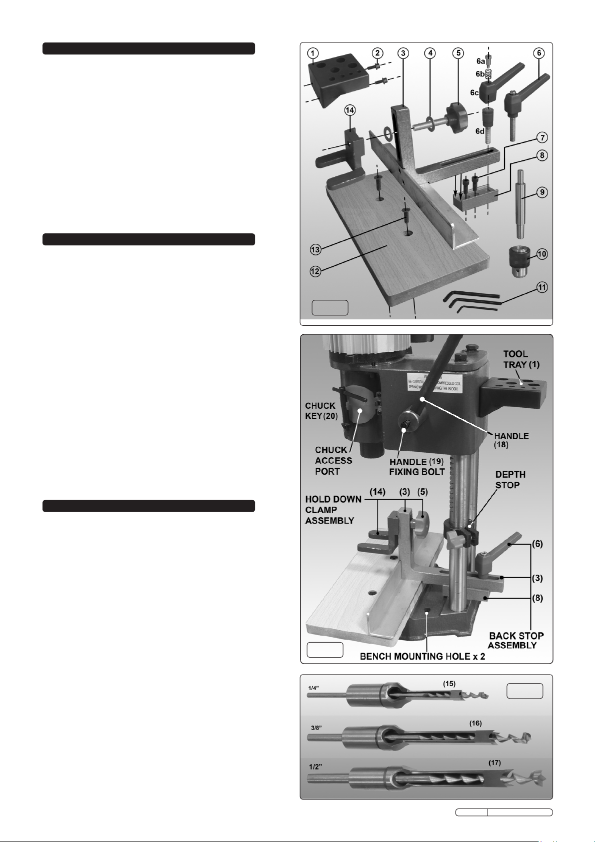
3. CONTENTS
CONTENTS (See Fig.1)
1. Tool tray
2. Tool tray fixings (2 x M6 x16mm socket cap bolts & washers)
3. Back Stop
4. Washers x 2 for hold down clamp assembly
5. Hold down clamp adjustment knob
6. Back Stop clamp assembly
6a. Clamp lever fixing
6b. Clamp lever spring
6c. Clamp lever
6d. Clamp lever post
7. Back Stop mounting block fixings (2 x M8 x 20mm socket cap bolts)
8. Back Stop mounting block
9. Arbour extension
10. Drilling chuck
11. Allen Keys 3mm, 5mm, 6mm
12. Work table
13. Table fixing screw (2 x M8 x 25mm Countersunk)
14. Hold down clamp
15. Mortising Chisel + Drill Bit (1/4”) (See Fig.3)
16. Mortising Chisel + Drill Bit (3/8”) (See Fig.3)
17. Mortising Chisel + Drill Bit (1/2”) (See Fig.3)
18. Handle (See Fig.2 & Fig.4)
19. Handle fixing bolt (M6 x 20mm) (See Fig.2)
20. Chuck Key. (See F ig.2)
4. ASSEMBLY
4.1 ASSEMBLY
WARNING! DO NOT plug the mortiser into the mains
power supply until completely assembled and these
instructions tell you to do so.
DO NOT allow brake fluids, petroleum, penetrating oils etc. to
come into contact with plastic parts of mortiser as damage
may result.
WARNING! The Mortiser is delivered with the head positioned
low down on the two pillars and is held in this position by a
piece of wood inserted between the top of the head and the
crosspiece on top of the pillars. Care must be taken when
removing this piece of wood as the head is held under spring
pressure and will move rapidly to the top of the pillars when
the wood is removed.
4.1.1 Releasing The Head. Place the mortiser onto a firm, solid
workbench and bring the cast base near to the front edge of
the work surface. Insert the plain end of the handle (18)
through the hole in the shaft on the right side of the head and
fix the handle with the M6 x 20mm socket cap bolt provided
(19). Steady the mortiser by placing your left hand on top of
the unit. Rotate the handle so that it is pointing downwards at
45°. Push the handle further down a small amount to take the
pressure off the wood and get a second person to remove the
piece of wood. Slowly allow the handle to rotate upwards
allowing the head to move to the top of the pillars in a
controlled fashion.
4.2 Back Stop Mounting Block. (See 8 in Figs.1 & 2) Bolt the
Back Stop mounting block in between the two pillars at the
back of the base casting using the two M8 x 20mm socket
Original Language Version
Fig.1
Fig.2
Fig.3
SM94.V4 Issue No.1 031209
Page 3

cap bolts provided (7). Ensure that the threaded hole is at
the back. TIghten the bolts using the 6mm allen key
provided.
4.3 Work Table. (See 12 in Figs.1 & 2) Attach the Work Table to
the cast base using the two countersunk M8 x 25mm Table
fixing screws (13).
4.4 Back Stop Assembly. (See Fig.2) Lay the Back Stop onto
the work table with the long extension resting in the guide
block (8). Place the Clamp Lever Post (see 6d in Fig.1)
through the slot in the guide and screw it down by hand into
the threaded hole in the Back Stop mounting block.
4.4.1 Place the Clamp Lever (see 6c in Fig.1) onto the top of the
clamp post ensuring that it engages with the splines on the
post.
4.4.2 Insert the spring (6b) into the recess in the top of the clamp
lever. Secure the clamp lever assembly with the clamp lever
fixing (6a) screwed down through the spring.
4.4.3 The movement of the clamp lever is restricted by its proximity
to the two pillars. To overcome this, the lever can be lifted up
from the splined top of the post and rotated round to a new
position in order to move it again. Ensure that the lever
re-engages with the splined post when dropped down again.
4.5 Hold Down Clamp Assembly. (See Figs.1 & 2) Slide a
washer (4) over the threaded shaft of the hold down clamp
adjustment knob (5). Insert the threaded shaft through the
vertical extension of the Back Stop (3) and slide on another
washer (4). Place the hold down clamp on the front face of
the Back Stop extension and screw the threaded shaft into
the clamp until it is firmly fixed on the Back Stop.
4.6 Tool Tray Assembly. Take the tool tray (1) and fix it to the
back of the head as shown in Fig.2 using two M6 x16mm
socket cap bolts & washers (2).
4.7 Mounting The Mortiser. Before use, attach the mortiser to a
stable work bench using the mounting points situated behind
the wood working table (Fig.2) and 13mm bolts of the
appropriate length which are strong enough to take the
weight of the unit and the workpiece.
WARNING! Failure to adequately mount the mortiser could
result in damage and/or severe personal injury.
Fig.4
5. INSERTING CHISEL & DRILL BIT
WARNING! Ensure the mortiser is switched off and is
unplugged from the mains power supply.
WARNING! Use gloves or a cloth when handling drill and
chisel bits, as the ends are very sharp. Remember to remove
gloves and/or cloth before starting the mortiser.
Note: If the mortiser has previously been set up for drilling,
the chuck and arbor extension must be removed before a
chisel can be installed.
5.1 Ensure that the socket cap chisel retaining screw (Fig.5-3) is
not protruding through the chisel mounting bush (Fig.5-2) so
that a chisel can easily be inserted into the bush.
5.2 When the chisel/drill bit is correctly set up there should be a
clearance of between 0.8 and 1.6mm between the end of the
chisel and the drill cutting spur. (See Fig.5) To do this use the
following procedure.
5.3 Open the head side covers (Fig 5.1) to expose the chuck
(Fig 5.6). Ensure that the jaws in the chuck are sufficiently
retracted to allow the chosen drill to fully enter the chuck.
5.4 Remove the protective cover from the end of the chisel/drill
set and hold a protective pad or small piece of wood on the drill
tip. Push the chisel/drill set up into the chisel bush until it
stops.
5.5 Now rotate the chisel portion so that the opening in the side
faces to the left or right. If the workpiece is to be moved
progressively to the right the opening in the side of the
chisel should face to the right. If moving the workpiece to the
left then face the opening to the left. Do not face the slot to
the front or rear because wood chips produced during the
cutting process will not be able to escape from the chisel.
5.6 Tighten the chisel retaining screw (Fig.5-3) using the hex key
provided.
5.7 Keeping the protective pad on the drill tip, push the drill up
into the chisel until the drill spur has a clearance of 0.8 -
1.6mm from the chisel (See inset diagram in Fig.5.) then
tighten the chuck using the chuck key provided.
5.8 Allow the side covers to close and remove any protection
from the chisel/drill tips.
Original Language Version
Fig.5
SM94.V4 Issue No.1 031209
Page 4

Fig.6
6. CONTROLS AND ADJUSTMENTS
WARNING! Ensure the mortiser is switched off and is
unplugged from the mains power supply.
6.1 Raising and lowering the mortiser head.
6.1.1 Handle. Use the handle (Fig.8) to raise and lower the head.
6.1.2 Pull the handle towards you to lower the head.
6.1.3 Allow the handle to return to raise the head.
6.1.4 Depth stop adjustment. See E in Fig.6. The depth stop
limits the depth of chisel cut. To adjust the depth stop, loosen
lock knob (Fig.6F) and lower the head until the bottom of the
chisel is at desired depth. Raise the depth stop until it makes
contact with the underside of the head and re-tighten knob.
6.2 Back stop. To position the back stop, loosen locking handle
(Fig.6D). Position back stop by moving it in or out as indicated
above, when correctly positioned re-tighten locking handle.
6.3 Hold Down Clamp adjustment. The clamp (Fig6A) prevents
the workpiece from lifting as the chisel is raised up from the
cutting hole. Adjust the clamp so that it rests on the top of the
workpiece but will allow the workpiece to slide to the left
or right. The clamp may be turned upside down to
accommodate thicker workpieces. To adjust the clamp
loosen the knob B and move the clamp up or down as
required and re-tighten the knob.
6.4 Parallel chisel adjustment. See Fig.7. Adjust the position of
the workpiece until it is almost touching the back of the
chisel (Y). Loosen the chisel retaining screw (X) to allow it to
rotate and edge the workpiece up to the back of the chisel to
ensure that the chisel is parallel to the surface of the
workpiece. Re-tighten the locking screw and reposition the
workpiece for cutting. See Fig.8.
7. OPERATING INSTRUCTIONS
WARNING! Ensure you read, understand and apply chapter 1
safety instructions before use.
7.1 Ensure you have installed the correct chisel and that it is
sharp. Ensure that the opening in the side of the chisel faces
to the left or right depending on which direction the workpiece
is to be moved in. Refer to section 5.5.
7.2 Set the depth stop. Refer to section 6.1.4.
7.3 Place your workpiece in the mortiser adjusting the back stop
and hold down clamp as necessary. Refer to sections 6.2 & 6.3.
7.4 Plug the mortiser into the mains power supply. Hold the
workpiece firmly against the back stop and switch the
mortiser on, keeping hands and fingers away from the cutting
tools.
7.5 Bring the handle down to commence mortise cutting. We
recommend that you practice on scrap wood before moving
onto an actual workpiece. The rate of chisel penetration must
be fast enough to prevent burning the drill and chisel tip, but
not too fast as to stall the motor. You may notice smoke
coming from the bit or the wood once the chisel has engaged
in the workpiece. This is a normal occurrence of hollow chisel
mortising caused by chipping friction whereby the wood
resins in the stock are burned off. Should this become
excessive however, refer to troubleshooting chapter 9.
The chisel may also become blue in colour, this is also a
normal attribute associated with friction and resin build up on
the cutting face of the tool bit. A dull (blunt) chisel may be
detected when the amount of pressure required to complete a
cut becomes excessive.
7.6 When performing a through mortise, a thin piece of wood
must be placed between the workpiece and the table to
prevent the underside of the cut from splintering, and to
protect the work table. In such a case re-set depth stop
accordingly.
7.7 Using the mortiser as a standard pillar drill
Loosen bushing screw and remove the chisel and drill bit
from the chuck.
Attach the chuck arbor extension spindle (Fig.1-9) to the
neck of spare drill chuck (Fig.1-10). Pass the spindle up
through, BUT DO NOT tighten the screw on the drill spindle
which must remain free to turn in the bush. A standard drill bit
may be used with chuck (10) for drilling. All locks and guides
are used in the same way as for mortising.
8. MAINTENANCE
WARNING! Ensure the mortiser is switched off and is
unplugged from the mains power supply before carrying out
any maintenance.
8.1 Clean and dust the mortiser, removing all waste materials.
8.2 Periodically apply a light coat of wax to base work surface
which will help keep it clean and rust free.
8.3 Open shaft cover and apply a thin coat of light machine oil to
drill bit shaft where it passes through the chisel, but not on the
cutting edge. Also lightly oil rack and pinion gear teeth upon
which the main column moves up and down.
Fig.7
Original Language Version
Fig.8
SM94.V4 Issue No.1 031209
Page 5

9. TROUBLESHOOTING
THE PROBLEM THE CAUSE THE SOLUTION
Noisy operation Dry drill bit shaft Lubricate drill bit shaft
Bit burns or smokes 1. Chips not coming out of hole 1. Retract bit frequently to clear chips
2. Dull bit 2. Sharpen or replace bit
3. Feed rate too slow 3. Feed faster
Excessive drill bit run out, or wobble 1. Bent bit 1. Replace bit
2. Chuck not correctly installed 2. Remove chuck and install correctly
3. Bit not correctly installed 3. Remove bit and install correctly
4. Worn or loose chuck 4. Replace chuck
5. Worn spindle bearings 5. Replace bearings
Drill binds in workpiece 1. Workpiece twisting or moving 1. Support or clamp workpiece
2. Excessive feed pressure 2. Reduce pressure and clamp workpiece
NOTE: It is our policy to continually improve products and as such we reserve the right to alter data, specifications and component parts without prior notice.
IMPORTANT: No liability is accepted for incorrect use of this product.
WARRANTY: Guarantee is 12 months from purchase date, proof of which will be required for any claim.
INFORMATION: For a copy of our latest catalogue and promotions call us on 01284 757525 and leave your full name and address, including postcode.
Sole UK Distributor, Sealey Group,
Kempson Way, Suffolk Business Park,
Bury St. Edmunds, Suffolk,
IP32 7AR
Original Language Version
01284 757500
01284 703534
www.sealey.co.uk
Web
sales@sealey.co.uk
email
SM94.V4 Issue No.1 031209
 Loading...