

Page 1
INSTRUCTIONS FOR:
METAL CUTTING BANDSAW
MODEL No : SM5.V3
Thank you for purchasing a Sealey quality product. Manufactured to a high standard this product will, if used according to these instructions
and properly maintained, give you years of trouble free performance.
IMPORTANT
BEFORE USING THIS PRODUCT, PLEASE READ THE INSTRUCTIONS CAREFULLY. MAKE CAREFUL NOTE OF SAFETY INSTRUCTIONS,
WARNINGS AND CAUTIONS. THIS PRODUCT SHOULD ONLY BE USED FOR ITS INTENDED PURPOSE. FAILURE TO DO SO MAY CAUSE
DAMAGE AND/OR PERSONAL INJURY AND WILL INVALIDATE THE WARRANTY. KEEP THESE INSTRUCTIONS SAFE.
1. SAFETY INSTRUCTIONS
1.1. ELECTRICAL SAFETY
WARNING! It is the user’s responsibility to read, understand and comply with the following:
You must check all electrical equipment and appliances to ensure that they are safe to use. You must inspect power supply leads, plugs and
all electrical connections for wear and damage. You must ensure the risk of electric shock is minimised by the installation of appropriate safety
devices. An RCCB (Residual Current Circuit Breaker) should be incorporated in the main distribution board. We also recommend that an RCD
(Residual Current Device) is used with all electrical products. It is particularly important to use an RCD with portable products that are plugged
into an electrical supply not protected by an RCCB. If in doubt consult a qualified electrician. You may obtain a Residual Current Device by
contacting your Sealey dealer. You must also read and understand the following instructions concerning electrical safety.
1.1.1. The Electricity At Work Act 1989 requires all portable electrical appliances, if used on business premises, to be tested by
a qualified electrician, using a Portable Appliance Tester (PAT), at least once a year.
1.1.2. The Health & Safety at Work Act 1974 makes owners of electrical appliances responsible for the safe condition of the appliance
and the safety of the appliance operator. If in any doubt about electrical safety, contact a qualified electrician.
1.1.3. Ensure the insulation on all cables and the product itself is safe before connecting to the mains power
supply. See 1.1.1. & 1.1.2. above and use a Portable Appliance Tester (PAT).
1.1.4. Ensure that cables are always protected against short circuit and overload.
1.1.5. Regularly inspect power supply, leads, plugs for wear and damage and all electrical connections to
ensure that none is loose.
1.1.6. Important: Ensure the voltage marked on the product is the same as the electrical power supply
to be used and check that plugs are fitted with the correct capacity fuse. A 13 amp plug may
require a fuse smaller than 13 amps for certain products, see fuse rating at right.
1.1.7. DO NOT pull or carry the powered appliance by its power supply lead.
1.1.8. DO NOT pull power plugs from sockets by the power cable.
1.1.9. DO NOT use worn or damage leads, plugs or connections. Immediately replace or have repaired by
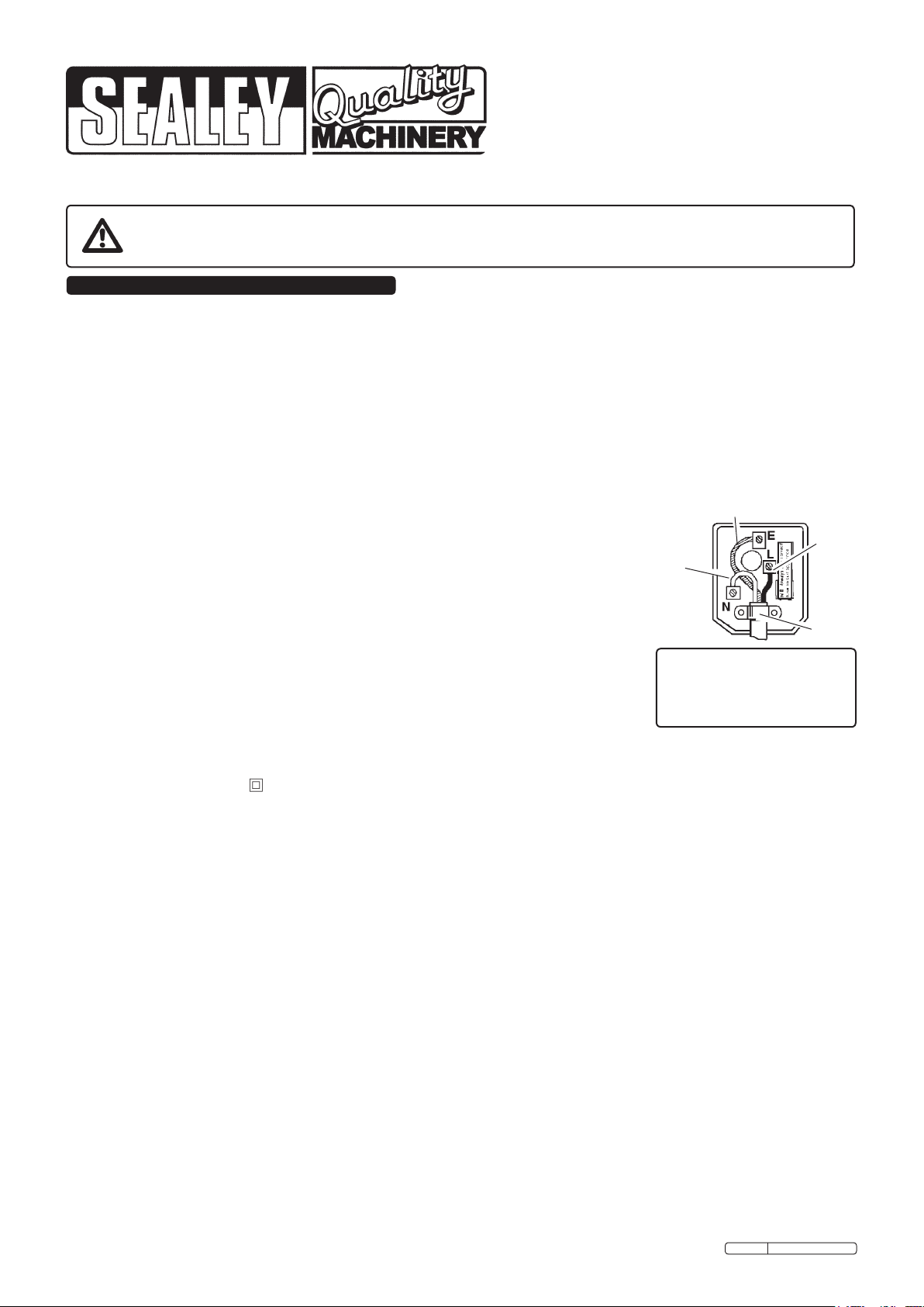
a qualified electrician. A U.K. 3 pin plug with ASTA/BS approval is fitted. In case of damage, cut
off and fit a new plug according to the following instructions (discard old plug safely).
(UK only - see diagram at right). Ensure the unit is correctly earthed via a three-pin plug.
a) Connect the GREEN/YELLOW earth wire to the earth terminal ‘E’.
b) Connect the BROWN live wire to live terminal ‘L’.
c) Connect the BLUE neutral wire to the neutral terminal ‘N’.
d) After wiring, check that there are no bare wires, that all wires have been correctly
connected, that the outer cable insulation extends beyond the cable restraint and that the cable restraint is tight.
Double insulated products are often fitted with live (BROWN) and neutral (BLUE) wires only. Double insulated products are always
marked with this symbol . To re-wire, connect the brown & blue wires as indicated above. DO NOT connect the brown or blue
to the earth terminal.
1.1.10. Cable extension reels. When a cable extension reel is used it should be fully unwound before connection. A cable reel with an RCD
fitted is recommended since any product which is plugged into the cable reel will be protected. The section of the cores of the cable is
important and should be at least 1.5mm². However, to be absolutely sure that the capacity of the cable reel is suitable for this
product and for others that may be used in the other output sockets, we recommend the use of 2.5mm² section cable.
1.2. GENERAL SAFETY
WARNING! Disconnect the bandsaw from the power source before servicing, changing accessories, or performing any other maintenance.
Familiarise yourself with the applications and limitations of the product, as well as the potential hazards.
Maintain the bandsaw in top condition. Keep it clean and keep blades sharp for best and safest performance.
Use original Sealey spare parts only. Unauthorised parts may be dangerous and will invalidate the warranty.
Keep all guards and fixing screws in place, tight and in working order. Check regularly for damaged parts. A guard or any other part that
is damaged must be repaired or replaced before the saw is used further. Check also for incorrect alignment of moving parts, loose
mountings, or any other condition that could affect the operation of the saw.
Ensure the space allocated for use and maintenance of the machine is adequate, free from unrelated materials and has good lighting.
Wear approved eye and ear protection when operating the machine. If dust is produced, wear an approved face or dust mask.
Keep children and unauthorised persons away from the work area, especially when the saw is in operation.
Remove any adjusting keys and wrenches from the machine before operating.
Ensure that large or oversized workpieces are supported at table height. Ensure you use a suitable support for any workpiece that does
not have a flat surface. Be cautious when cutting workpieces which are irregular in cross-section as the saw blade could be pinched
before the cut is completed. Any stock such as frame moulding, must lay flat on the table surface and not be allowed to rock.
WARNING! Round bar and tubing have a tendency to roll while being cut and cause the blade to “bite”. DO NOT cut such items without
clamping or blocking the workpiece.
WARNING! Never force the blade through the workpiece.
Do not use this bandsaw for anything other than its intended purpose. This bandsaw is designed for light metal cutting work in
engineering workshops, garages, metal fabricators, etc. .
WARNING! The SM5.V3 bandsaw MUST NOT be used to cut non-metallic materials (including wood). To do so will invalidate
your insurance cover and your warranty and may cause damage and/or personal injury.
Do not wear loose or ill-fitting clothing. Remove ties, watches, rings and other jewellery. Tie up, or adequately cover, long hair.
Do not start the bandsaw until the workpiece is secure and the blade has been lowered to just above the workpiece.
Original Language Version
Blue
Neutral
Wire
Yellow & Green
Earth Wire
Brown
Live
Wire
Cable
Restraint
FUSE RATING
THIS PRODUCT MUST
BE FITTED WITH A
5 AMP FUSE
SM5.V3 Issue: 4 - 25/03/10
Page 2
Do not run the bandsaw with the blade in the raised position unless set up for vertical cutting.
Do not use the bandsaw in areas where fumes from paint, solvents, or flammable liquids pose a potential hazard. Keep all flammable
materials (including wipes or cleaning rags) away from the saw, and dispose of according to local regulations.
Do not leave the bandsaw running unattended. Turn power switch ‘Off’ and do not leave area until the blade has come to a complete
stop.
Do not use whilst under the influence of drugs, alcohol or other intoxicating medication. Do not use the bandsaw if you are fatigued.
Do not use the bandsaw with the blade guard or pulley cover removed
Do not use the bandsaw in wet or damp locations.
Do not start accidentally. Ensure the switch is off before plugging in the saw.
Do not use damaged or deformed bandsaw blades.
Keep correct footing and balance at all times and wear non-slip shoes.
Turn the bandsaw off before raising the blade.
Do not stand on the bandsaw.
Always secure the workpiece in the vice.
2. INTRODUCTION & SPECIFICATION
The SM5.V3 has a heavy duty cast base and arm with a fully guarded blade for horizontal and vertical cutting of light metals. A magnetic no-load voltage
switch prevents the motor from automatically re-starting after a power failure or a blade jam. An oil-bath gear box and sealed-for-life drive bearings give
fast and smooth operation. The saw base features an integral mitreing vice with a 0-to-450 scale for angle cutting. Fully adjustable precision blade guides
provide accuracy and long blade life.
2.1. Specification
Capacity 90° round ............................................................................ Ø115mm
Capacity 90° square/rectangular H x W .....................................100 x 150mm
Capacity 45° round .............................................................................. Ø60mm
Capacity 45° square/rectangular H x W .......................................100 x 60mm
Weight ......................................................................................................60kg
Blade Size ......................................................................12.7 x 0.7 x 1638mm
Blade Speeds .................................................................... 0.3, 0.5, 0.8mtr/sec
Motor Power ............................................................................... 375W (1/2hp)
Power Supply ....................................................................................230V/1ph
3. ASSEMBLY AND SETUP
3.1. ASSEMBLY. Note: Numbers in brackets refer to Parts Diagram
Items.
3.1.1. Remove the unit from packing and check that all items in the following
list are present and undamaged: Saw Assembly, Pulley Cover, Shelf,
Floor Stands (2 off), Stock Stop & Rod Assembly, Hand Wheel, Vice,
Axle & Wheels Assembly, Handle, Floor Stand, Vertical Cutting Table,
Drive Belt, Bag of screws, washers, nuts, split pins & hex. key.
3.1.2. Fit the floor stands, (4) - right and (13) - left, to the saw base (37)
using screws (11), washers (51) and nuts(12).
3.1.3. Fit the shelf (170) between the stands using screws (171), washers
(173) and nuts (172).
3.1.4. Attach the axle and wheels assembly (5) to the right hand floor stand
using screws (1), washers (3) and nuts (2) provided.
3.1.5. Fit handle (14) to the left hand floor stand and retain with split pins (6).
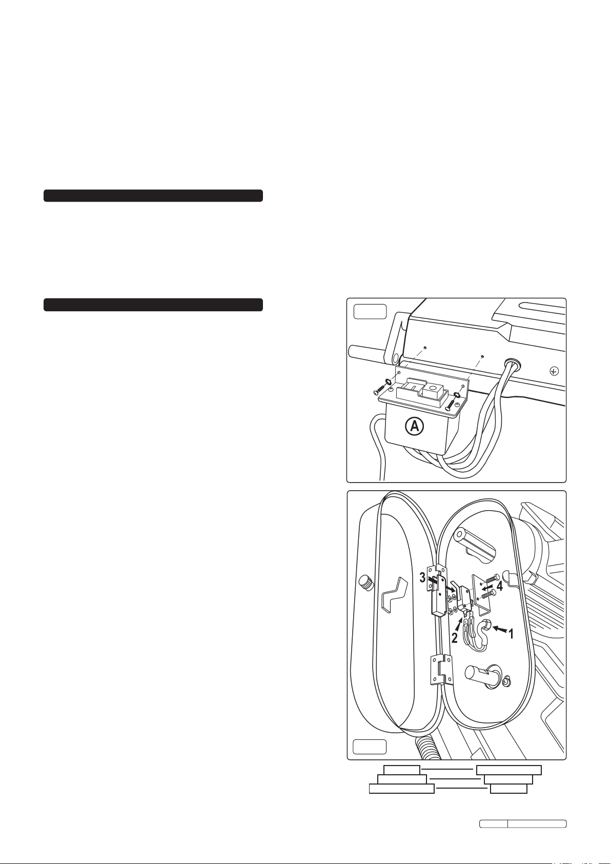
3.1.6. Attach switch box (A) to lower left hand edge of base using screws &
washers supplied. ( See fig.A )
3.1.7. Fit hand wheel (28) to vice shaft (32) and tighten grub screw (20) onto
flat on shaft.
3.1.8. Attach pulley cover (110) to body frame with screws (1) & washers (3).
3.2 The microswitch assembly should be fitted after the pulley cover/box
is in place but before the pulleys and belt are attached. Refer to figure B.
3.2.1. Detach microswitch & its cover from bracket by undoing the two nuts
and bolts.
3.2.2. ( See fig.B-1.) Feed microswitch cable through hole in base of pulley box.
3.2.3. ( See fig.B-2.) Push the two connectors onto the terminals on the
microswitch. The wires can be connected either way round.
3.2.4. ( See fig.B-3.) Slide the microswitch cover over the top of the
microswitch and connectors and line up the holes in the cover with the
holes in the microswitch.
3.2.5. ( See fig.B-4.) Bolt the microswitch and cover to the bracket using the
nuts, bolts and washers supplied ensuring that the assembly is on the
left hand side of the bracket as shown in fig.B.
3.2.6. Take the black cable clamp/grommet supplied and slide it over the
cable, close to the underside of the pulley cover and close the
grommet. Adjust the position of the cable within the grommet if
neccessary and then push the grommet firmly into the hole. See fig.B-1.
3.3. Attach motor pulley (86) to motor shaft and retain with grub screw (20).
3.3.1. Attach gearbox pulley (101) to worm gear shaft and retain with grub
screw (20).
3.3.2. Fit the drive belt (112) and refer to paragraph 3.3.
3.3.3. Adjust motor position to obtain correct belt tension by tightening tension
screw (98), then close pulley cover.
3.3.4. Slide stock stop rod (21) into base and tighten set screw (20) to retain.
3.3.5. Adjust abutment screw (53) so that, with body frame down, blade cutting
edge is below surface of base but body frame is clear of base. Tighten
lock nut (122).
3.3.6. Adjust switch cut-off tip (76) to ensure that ‘Off’ switch is actuated when,
or just before,
body frame contacts abutment screw (53). Tighten scew.
3.4. Adjusting blade speed. Adjust the blade speed to suit the metal to be
cut. The recommended pulley selections are shown in the chart below/
right.
Original Language Version
fig.A
fig.B
Motor Pulley
A
B
C
D
E
F
Saw Pulley
SM5.V3 Issue: 4 - 25/03/10
Page 3

3.4.1. Disconnect saw from power supply and open the pulley cover.
3.4.2. Loosen tension screw (98) on the motor plate to slacken the belt.
3.4.3. Move the belt to the required pulley grooves (see chart below ).
3.4.4. Tension belt by tightening screw (98) and close the pulley cover..
3.5. Blade selection. The chart below shows the recommended set up for various metals and cut lengths. Blades are available from your
Sealey dealer in four tooth pitches: 6, 10, 14 and 24 tpi (see parts list).
Cutting Chart for Flat and Round Bar
Recommended blade teeth per inch (tpi) for nominal cut length
Cut length Under 8mm 4-13mm 6-16mm 8-22mm
Tpi 32 24 18 14
Cut length 10-35mm 17-40mm 25-50mm 38-75mm
Tpi 10 8 6 4
Cut length 50-100mm 75-150mm 114-225mm >200mm
Tpi 3 2 1.25 0.75
4. OPERATION
Recommended Pulley Selection for Various Metals
Material Motor Pulley
Tool, stainless or alloy steel.
Bearing bronze.
Low to medium carbon steel.
Aluminium. Copper. Brass.
Small (A)
Medium (B)
Large (C) Small (F)
Saw Pulley
Large (D)
Medium (E)
Blade Speed
20m/min
29m/min
50m/min
WARNING! Before operating the bandsaw ensure that you read, understand and apply the safety instructions in Section 1.
NOTE: Before operating the machine certain checks and adjustments will need to be carried out. It is very important that
these instructions are followed carefully in order that the machine is set up safely and correctly.
WARNING! The machine is designed for light metal cutting work in engineering workshops, garages, metal fabricators, etc.
The SM5.V3 must not be used to cut any other materials (including wood). To do so will invalidate your insurance cover and your
warranty and may cause damage and/or personal injury.
Note: The harder the material being cut, the slower the cutting speed should be. The use of a cutting oil is recommended with the higher
blade speeds.
4.1. HORIZONTAL CUTTING
fig.1
4.1.1. Ensure that the saw is
disconnected from the power
supply.
4.1.2. Adjust the blade speed to suit the
workpiece material (see para. 3.3).
4.1.3. Raise the saw arm to the vertical
position.
4.1.4. Adjust the stock stop to the desired
length.
4.1.5. Loosen the fixed vice plate bolts
(11 & 52) and adjust the vice to the
desired angle, see 0-to-450 scale
(39) on bed. Retighten bolts.
Loosen the moveable vice plate
bolt (36) and wind plate up to
fixed plate so that plates are fully
touching. Tighten bolt (36) to
maintain moveable plate parallel to
fixed plate.
4.1.6. Open vice, insert the workpiece
and clamp it securely.
4.1.7. Adjust the two blade guides, by slackening the clamp screws (56 & 66), so that they are close to the workpiece but will not foul it.
4.1.8. Gently lower the arm until the blade is just above the workpiece. Connect the saw to the power supply and start the saw.
DO NOT turn on machine until workpiece is secured and blade has been lowered to just above
workpiece.
4.1.9. Bring the blade into contact with the workpiece and then release the arm. If the blade jams and
fig.2
the saw does not automatically shut off, immediately disconnect it from the power supply.
Refer to the ‘Troubleshooting’ section for common problems.
4.1.10. When sawing is completed disconnect from the power supply, raise blade and remove
workpiece.
WARNING! Never raise blade when machine is running and never run machine when
blade is raised (unless correctly set up for vertical cutting).
4.2. VERTICAL CUTTING
4.2.1. Ensure that the saw is disconnected from the power supply.
4.2.2. Adjust the blade speed to suit the workpiece material (see para. 3.4).
4.2.3. Raise the saw arm to the vertical position and rotate the support plate (18) so that it
engages into the notch in the edge of the main body frame (see fig.2 -18)
4.2.4. Remove the two screws (68) from the end face of the lower blade guide, remove blade
guard (69) and replace with table (55) and its support (56). Loosen the lower blade
guide nut and washer sufficiently to allow the slotted end of the support to pass
between the washer and body frame and then retighten the nut. Retain table by
replacing screws (68) (see fig.2)
4.2.5. Adjust the upper blade guide so that no more blade is exposed than is required to cut the
workpiece.
4.2.6. When cutting keep hands well clear of the blade and always use a push stick for small
workpieces.
4.2.7. When cutting is complete immediately switch off saw.
WARNING! Refit blade guard (69) before using saw for horizontal cutting.
Original Language Version
SM5.V3 Issue: 4 - 25/03/10
Page 4

5. BLADE CHANGING & ADJUSTMENTS
WARNING! BEFORE MAKING ANY ADJUSTMENTS, DISCONNECT SAW FROM POWER SUPPLY.
5.1. All adjustments that relate to the smooth and safe running of the blade have been set at the factory. However, if you require to replace
a blade due to it being worn out or if you need to change to a blade with a different tooth size it will be necessary to readjust the saw.
5.2. CHANGING & TENSIONING THE BLADE :
WARNING! Take care when handling saw blades, blade teeth are very sharp.
5.2.1. Raise the sawing arm to the vertical position and engage the support plate (see fig.2 - 18)
5.2.2. Open the blade back safety panel by removing the plastic headed thumb screw (58) and hinging it open as shown in fig.3.
5.2.3. Before the blade can be removed release the tension on the blade by turning the blade
tension knob (79) anticlockwise .
5.2.4. Remove the lower blade guide (69) and loosen the lowest screw on the upper blade
guide and slide the guide away from the blade to the end of its slotted mounting hole.
5.2.5. Ease the blade away from the lowest pulley wheel first and support it as you remove it
from the upper pulley wheel then carefully remove the blade from between the guides.
5.2.6. Place the new blade through the guides first and then ease it around the lower pulley
wheel. (Ensure that the tooth direction is consistent with the blade travelling left to right
in the cutting area.) Retain the blade on the lower pulley with one hand and take up the
tension at the top of the blade with the other hand. Then use both hands to ease the
blade over the upper pulley.
5.2.7. Begin to tension the blade by turning the knob (79) clockwise but as you do so make
sure that the back edge of the blade is seated against the rim of both pulleys. Check that
the blade is seating properly by turning the upper pulley by hand ( using the three
spokes of the wheel ) until you have observed a full rotation of the blade.
5.2.8. Once the blade is properly aligned increase the tension until the blade flexes by
approx.1mm when pressed at the midway point between the two pulleys.
5.2.9. Replace the lower blade guard (69) and move the upper blade guide back into its
position over the blade.
5.2.10. Close the blade protection safety cover and secure it with the plastic headed thumb
screw.
5.2.11. Reconnect the saw to the power source and run it for two to three minutes to seat the
blade.
5.2.12. Disconnect the saw from the mains. Open the blade back safety cover and recheck the
tension and adjust if required. Close safety cover.
5.3. BLADE TRACKING ADJUSTMENT
Adjustment of the blade tracking is necessary to prevent the blade from twisting or
coming off the blade wheels.This adjustment should also be made whenever a new
blade is fitted (see section 5.2).
5.3.1. Run saw for a short time and then switch off.
5.3.2. Raise saw arm, open blade safety panel and check blade-to-wheel relationship.
Rear edge of blade should be very close to, but not hard against, the wheel flanges.
5.3.3. If inspection indicates that adjustment is required reduce blade tension (see para. 5.2.3.)
and loosen the blade tracking lock nut as seen in fig.4.
5.3.4. Place a 4mm hex tool into the adjuster and rotate in or out as required whilst rotating the
upper pulley by hand (using the three spokes of the wheel ) until tracking appears
corrected. Re-tighten the blade tracking lock nut.
5.3.5. Having made a small adjustment, tension blade, replace blade cover, lower arm and
run saw for a short time.
5.3.6. Switch saw off, remove blade cover and check tracking. Repeat adjustment procedure if
necessary.
5.4. BLADE GUIDE BEARING ADJUSTMENT
Correct guide bearing adjustment is important so that the blade runs smoothly and
evenly without twisting or snagging anywhere along its path. Each of the outer guide
bearings is mounted on an adjustable eccentric bushing.
5.4.1. Disconnect the machine from the power supply.
5.4.2. Loosen the lock nut while holding the bearing bolt with an open ended spanner.
(See fig.5)
5.4.3. Turn the bolt to adjust the bearing. The bearing should barely touch the blade
(0.001”). This clearance can be measured with a piece of thin paper which should
just fit into the gap between the bearings and the blade. Tighten the lock nut when
satisfied with the bearing adjustment.
5.4.4. Adjust both outer guide bearings. When satisfied that the adjustment is accurate,
carefully turn the blade wheels by hand to see if the blade snags or rubs at any point.
Readjust bearing(s) if necessary.
fig.3
BLADE TRACKING
LOCK NUT ADJUSTER
fig.4
fig.5
fig.6
5.5. BLADE GUIDE ADJUSTMENT
5.5.1. Disconnect the machine from the power supply. ( Figure 6 shows the blade guard 69
removed for clarity. It is not necessary to remove the blade guard to make the following
adjustments.)
5.5.2. To adjust the blade guide loosen the bolt indicated in fig.6. and allow the single bearing
which runs on the back of the blade to rest on the blade without exerting any pressure.
5.5.3. Rotate the blade guide (as shown in fig.6 ) until blade is perpendicular to machine bed.
5.5.4. Retighten the hex bolt ensuring that no pressure is applied to the back of the blade.
Adjust the second blade guide in the same manner.
Original Language Version
SM5.V3 Issue: 4 - 25/03/10
Page 5

5.6. CUTTING/FEED PRESSURE
The weight of the cutting arm itself applies pressure to the cutting blade and
fig.7
therefore to the workpiece. An adjustable spring is attached to the arm and as
the spring pressure is increased the cutting pressure is decreased.
5.6.1. If the saw is making crooked or rough cuts or overheating is occurring it may be
necessary to decrease the feed pressure by turning the chromed adjusting rod in
a clockwise direction as shown in fig.7.
5.6.2. If the saw blade becomes dull quickly it may be necessary to increase the feed
pressure by turning the chromed adjusting rod in an anticlockwise direction as
shown in fig.7.
6. MAINTENANCE
6.1. Clean saw after each operation and smear unpainted surfaces with oil to prevent rusting.
Lubricate vice lead screw (32) as necessary.
6.2. Annually replace gearbox oil (SAE 90) as follows:
6.2.1. With blade arm horizontal remove gearbox cover screws (75), cover (93) and gasket (92).
6.2.2. Place oil container under right hand lower corner of gearbox and then carefully raise saw arm fully to drain oil.
6.2.3. Lower saw arm, remove any remaining oil from gearbox with clean cloths and then refill with fresh oil. Replace cover and gasket.
7. TROUBLESHOOTING
Excessive blade breakage and/or
teeth ripping from the blade.
Premature blade dulling.
Unusual wear on side or back of
blade.
Motor overheating.
Bad, crooked or rough cuts.
Blade is twisting.
1. Workpiece is loose in the vice.
2. Incorrect speed or feed.
3. Blade is too coarse.
4. Workpiece material is too coarse.
5. Incorrect blade tension.
6. Blade is in contact with workpiece before
saw is started.
7. Blade is rubbing on the wheel flange.
8. Blade guides are misaligned.
9. Blade is too thick.
10. Bad weld on blade
1. Blade tpi is too high.
2. Incorrect speed - too fast.
3. Inadequate feed pressure.
4. Hard spots or scale on the workpiece.
5. Blade is twisting.
6. Insufficient blade tension.
7. Blade is slipping.
1. Blade guides are worn.
2. Blade guides are misaligned.
3. Blade guide brackets are loose.
1. Blade tension too high.
2. Drive belt tension too high.
3. Blade too coarse or too fine.
4. Gears need lubrication.
5. Blade is binding in the cut.
1. Feed pressure too great.
2. Blade guides are misaligned.
3. Inadequate blade tension.
4. Blade is dull.
5. Incorrect speed.
6. Blade guides are spaced out too far.
7. Blade guide assembly is loose.
8. Blade is too coarse.
1. Blade is binding in the cut.
2. Blade tension is too high.
1. Clamp the workpiece securely.
2. Adjust the speed or feed to suit the workpiece.
3. Replace with a finer blade.
4. Use the saw at slower speed and use a smaller tpi blade.
5. Adjust blade tension so that it does not slip on the wheel.
6. Place blade in contact with the workpiece only after the saw has
started.
7. Adjust blade wheel alignment.
8. Adjust blade guide alignment.
9. Use correct thickness blade.
10. Re-weld or replace blade.
1. Replace with a smaller tpi blade.
2. Reduce speed.
3. Increase feed pressure by unscrewing tension bar. This will
decrease the spring tension on the arm.
4. Reduce speed, increase feed pressure.
5. Replace blade and adjust to the correct tension.
6. Increase blade tension.
7. Increase blade tension and reduce speed.
1. Replace blade guides.
2. Adjust guide pivots.
3. Tighten blade guide brackets.
1. Reduce blade tension.
2. Reduce drive belt tension.
3. Use a blade more suitable for the workpiece.
4. Lubricate the gears.
5. Decrease feed and speed.
1. Reduce feed pressure by screwing tension bar in. This will
increase the spring tension on the arm.
2. Adjust blade guides.
3. Increase blade tension.
4. Replace the blade.
5. Adjust the speed.
6. Adjust guide spacing.
7. Tighten the guide assembly.
8. Use a finer blade.
1. Decrease feed pressure.
2. Decrease blade tension.
NOTE: It is our policy to continually improve products and as such we reserve the right to alter data, specifications and component parts without prior notice.
IMPORTANT: No liability is accepted for incorrect use of this product.
WARRANTY: Guarantee is 12 months from purchase date, proof of which will be required for any claim.
INFORMATION: For a copy of our latest catalogue and promotions call us on 01284 757525 and leave your full name and address, including postcode.
Sole UK Distributor, Sealey Group,
Kempson Way, Suffolk Business Park,
Bury St. Edmunds, Suffolk,
IP32 7AR
Original Language Version
01284 757500
01284 703534
www.sealey.co.uk
Web
sales@sealey.co.uk
email
SM5.V3 Issue: 4 - 25/03/10
 Loading...