

Page 1

INSTRUCTIONS FOR:
FLOOR STANDING BELT/DISC
SANDER
MODEL No: SM15.V2
Thank you for purchasing a Sealey quality product. Manufactured to a high standard this product will, if used according to these instructions and properly
maintained, give you years of trouble free performance.
IMPORTANT: BEFORE USING THIS PRODUCT, PLEASE READ THE INSTRUCTIONS CAREFULLY. MAKE CAREFUL NOTE OF SAFETY
INSTRUCTIONS, WARNINGS AND CAUTIONS. THIS PRODUCT SHOULD ONLY BE USED FOR ITS INTENDED PURPOSE. FAILURE TO DO SO
MAY CAUSE DAMAGE AND/OR PERSONAL INJURY AND WILL INVALIDATE THE WARRANTY. RETAIN THESE INSTRUCTIONS FOR
1. SAFETY INSTRUCTIONS
1.1 ELECTRICAL SAFETY
WARNING! It is the user’s responsibility to read, understand and comply with the following:
You must check all electrical equipment and appliances to ensure they are safe before using. You must inspect power supply leads, plugs and
all electrical connections for wear and damage. You must ensure that risk of electrical shock is minimised by the installation of appropriate
safety devices. An RCCB (Residual Current Circuit Breaker) should be incorporated in the main distribution board. We also recommend that
an RCD (residual Current Device) is used with all electrical products. It is particularly important to use an RCD with portable products that are
plugged into an electricity supply not protected by an RCCB. If in doubt consult a qualified electrician. You may obtain an RCD by contacting
your Sealey dealer. You must also read and understand the following instructions concerning electrical safety.
1.1.1. The Electricity at Work Act 1989 requires all portable electrical appliances, if used on business premises, to be tested by a qualified
electrician, using a Portable Appliance Tester (PAT), at least once a year.
1.1.2. The Health & Safety at Work Act 1974 makes owners of electrical appliances responsible for the safe condition of the appliance and
the safety of the appliance operator. If in any doubt about electrical safety, contact a qualified electrician.
1.1.3. Ensure the insulation on all cables and the product itself is safe before connecting to the mains power
supply. See 1.1.1. and 1.1.2. above and use a PAT.
1.1.4. Ensure that cables are always protected against short circuit and overload.
1.1.5. Regularly inspect power supply, leads, plugs for wear and damage and all electrical connections
to ensure that none are loose.
1.1.6. Important: Ensure the voltage marked on the product is the same as the electrical power supply
to be used.
1.1.7. DO NOT pull or carry the powered appliance by its power supply lead.
1.1.8. DO NOT pull power plugs from sockets by the power cable.
1.1.9. DO NOT use worn or damaged leads, plugs or connections. Immediately replace or have
repaired by a qualified electrician. A U.K. 3-pin plug with ASTA/BS approval is fitted. In case of
damage cut off and fit a new plug according to the following instructions, discarding the old plug
safely.
(UK only - see diagram at right). Ensure the unit is correctly earthed via a three-pin plug.
(a) Connect the GREEN/YELLOW earth wire to the earth terminal ‘E’.
(b) Connect the BROWN live wire to the live terminal ‘L’.
(c) Connect the BLUE neutral wire to the neutral terminal ‘N’.
(d) After wiring, check that there are no bare wires, that all wires have been correctly connected, that the external insulation
extends beyond the cable restraint and that the restraint is tight.
1.1.10. Cable extension reels. When a cable extension reel is used it should be fully unwound before connection. A cable reel with an RCD
fitted is recommended, since any product which is plugged into the cable reel will be protected. The section of the cable on the
reel is important and should be at least 1.5mm², but to be absolutely sure that the cable capacity is suitable for this product, and for
others that may be used in the other output sockets, we recommend the use of 2.5mm² section cable.
FUSE RATING
13AMP
FUTURE USE.
1.2. GENERAL SAFETY
WARNING Disconnect the sander from the power source before servicing, changing accessories or performing any maintenance.
Familiarise yourself with the applications, limitations and potential hazards of the sander.
Use original Sealey spare parts only. Unauthorised parts may be dangerous and will invalidate the warranty.
Keep all guards and holding screws in place, tight and in working order. Check regularly for damaged parts. A guard or any other part
that is damaged should be repaired or replaced before the tool is next used.
Install the sander in a suitable work area. Keep area free from unrelated materials and ensure that there is good lighting.
Remove any adjusting keys and wrenches from the machine before operating.
Wear approved eye and ear protection when operating the machine. If dust is produced, wear an approved face or dust mask. A
complete range of approved safety products is available from your Sealey dealer.
Keep correct footing and balance at all times and ensure that the floor is not slippery. Wear non-slip shoes.
Keep children and unauthorised persons away from the work area, especially when the tool is in operation. Keep the area childproof
by using padlocks and master switches.
Support the workpiece with the backstop or work table.
Maintain no more than 1/16” (1.5mm) of clearance between the table and sanding belt or disc.
Feed the workpiece against the rotation of the sander. Hold the workpiece firmly so that it is not pulled from your hands.
Maintain the sander in good condition.
DO NOT use the sander for any task other than that for which it is designed - sanding wood.
DO NOT wear loose or ill-fitting clothing. Remove ties, watches, rings and other jewellery. Tie up, or adequately cover, long hair.
DO NOT use this machine in wet or damp locations.
DO NOT use the sander in areas where fumes from paint, solvents or flammable liquids pose a hazard. Dispose of all flammable
material according to local regulations.
DO NOT attempt to sand a workpiece that is too small to be safely held by hand.
DO NOT stand on the machine.
DO NOT leave the sander running unattended. Turn it off and do not leave the area until the disc/belt has come to a complete stop.
DO NOT use the sander whilst under the influence of drugs, alcohol or intoxicating medication.
DO NOT use the sander if you are tired.
Original Language Version
SM15.V2 Issue: 3 - 11/04/12
Page 2
2. SPECIFICATION
Belt Size. . . . . . . . . . . . . . . . . 152 x 1220mm
Belt Speed. . . . . . . . . . . . . . . . . . .330m/min
Disc Ø........................ . 230mm
Disc Speed. . . . . . . . . . . . . . . . . . . . 1400rpm
Table Size. . . . . . . . . . . . . . . . . 305 x 159mm
3. ASSEMBLY AND SETUP
Use the parts diagram at the back of these Instructions to assist in assembly.
3.1. Carefully unpack the contents and check that the following items are included:
Sander Body, Work Table, Mitre Gauge, Stand Panel, Stand Bracket, Stand Plate, Nuts,
Bolts and Washers, Rubber Feet, Hex Key and Backstop. If any items are missing or
damaged, contact your Sealey dealer.
3.2. Attach the rubber feet to the bottom of the two stand panels.
3.3. Attach the two stand brackets to the stand frame with the screws and nuts provided. Do
not tighten the screws until after the stand is completely assembled.
3.4. Attach the stand plate to the stand panels.
3.5. Tighten all screws on the stand.
3.6. Mount the sander to the stand plate with the bolts and nuts provided.
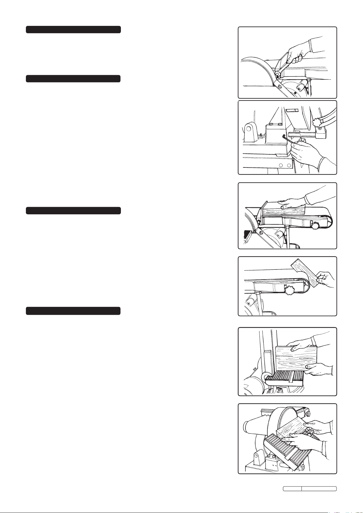
3.7. Mount the backstop (41) on the sander (fig. 1). The backstop will help support the
workpiece while sanding.
3.8. Assemble table (1) to support bracket (11) and attach angle gauge (7), pointer (13) and
support bar (18).
3.9. Attach the worktable assembly by loosening the set screw (14) (fig 2). Insert the table
rod (18) into the hole with the flat surface of the shaft facing the set screw. Tighten
the set screw. Note that you should leave a space of no more than 1.5mm
(1/16”) between the table and the sanding disc.
Table Tilt ...................... . . 0°-45°
Motor. . . . . . . . . . . . . . . . . . . . . .550W, 230V
Dimensions (H x W x L). . 995 x 455 x 715mm
Weight. . . . . . . . . . . . . . . . . . . . . . . . . . 55kg
fig. 1
fig. 2
fig. 3
4. OPERATION
This sander is designed for sanding wooden workpieces held by hand. If used for any
other purpose, the insurer will not provide coverage.
4.1. Ensure that the sander is disconnected from the power supply.
4.2. Make any adjustments to suit the work as described in Section 5.
4.3. Connect the sander to the power supply and turn it on.
4.4. Horizontal sanding - Place the workpiece on the belt. Hold it in place with both hands and
use the backstop for support (fig 3). Do not apply excessive pressure to the belt.
4.5. Curve sanding - Use the very end of the belt to sand curves (fig 4).
4.6. Vertical sanding - With the sanding arm in the vertical position, use the backstop and
table to help support the workpiece (fig 5).
4.7. Disc sanding - Use the sanding disc for end grain sanding, bevel sanding from
0°-45° (fig 6) or angle sanding (using the mitre gauge) from 0°-60° (fig 7).
4.8. When work is completed, turn off the sander and disconnect it from the power supply.
5. ADJUSTMENTS
WARNING - BEFORE MAKING ANY ADJUSTMENTS, DISCONNECT THE SANDER FROM
THE POWER SUPPLY!
5.1. Sanding belt replacement:
5.1.1. Loosen the two knobs (46) and move lever (84) to the right to remove
tension from belt.
5.1.2. Remove the old belt and replace with a new one.
5.1.3. Tighten the tension by moving lever fully to the left. Fully tighten knobs (46).
5.2. Sanding belt tracking:
5.2.1. To adjust belt tracking loosen knobs (46) and adjust tracking knob (46A) while
rotating belt by hand.
5.2.2. When tracking is correct tighten knobs (46) and check with motor running.
5.3. Sanding disc replacement:
5.3.1. Remove table assembly and open pulley cover (22).
5.3.2. Tear off the old sanding paper and clean off any glue remaining on the disc.
5.3.3. Attach new sanding paper, close pulley cover and replace table assembly.
fig. 4
fig. 5
fig. 6
Original Language Version
SM15.V2 Issue: 3 - 11/04/12
Page 3

5.4. Table adjustment (0° to 45°):
5.4.1. Loosen the screw (20) which clamps the angle gauge (7).
5.4.2. Adjust the table to the desired angle and tighten the screw.
5.5. Sanding arm vertical adjustment:
5.5.1. Remove safety cover (40) and loosen the two nuts (37), see fig. 8. Only one nut
is visible in the illustration.
5.5.2. Raise the arm to the vertical position and tighten the nuts.
5.5.3. Fit table assembly to support post on base.
fig. 7
fig. 8
NOTE: It is our policy to continually improve products and as such we reserve the right to alter data, specifications and component parts without prior notice.
IMPORTANT: No liability is accepted for incorrect use of this product.
WARRANTY: Guarantee is 12 months from purchase date, proof of which will be required for any claim.
INFORMATION: For a copy of our latest catalogue and promotions call us on 01284 757525 and leave your full name and address, including postcode.
Sole UK Distributor, Sealey Group,
Kempson Way, Suffolk Business Park,
Bury St. Edmunds, Suffolk,
IP32 7AR
Original Language Version
01284 757500
01284 703534
www.sealey.co.uk
Web
sales@sealey.co.uk
email
SM15.V2 Issue: 3 - 11/04/12
 Loading...