

Page 1
INSTRUCTIONS FOR:
BOBBIN SANDER
MODEL No: SM1301
Thank you for purchasing a Sealey product. Manufactured to a high standard this product will, if used according to these instructions
and properly maintained, give you years of trouble free performance.
IMPORTANT: PLEASE READ THESE INSTRUCTIONS CAREFULLY. NOTE THE SAFE OPERATIONAL REQUIREMENTS, WARNINGS & CAUTIONS.
USE THE PRODUCT CORRECTLY AND WITH CARE FOR THE PURPOSE FOR WHICH IT IS INTENDED. FAILURE TO DO SO MAY CAUSE
DAMAGE OR PERSONAL INJURY AND WILL INVALIDATE THE WARRANTY. PLEASE KEEP INSTRUCTIONS SAFE FOR FUTURE USE.
1. SAFETY INSTRUCTIONS
1.1. ELECTRICAL SAFETY. WARNING! It is the user’s responsibility to read, understand and comply with the following:
You must check all electrical equipment and appliances to ensure they are safe before using. You must inspect power supply leads, plugs and
all electrical connections for wear and damage. You must ensure the risk of electric shock is minimised by the installation of appropriate safety
devices. An RCCB (Residual Current Circuit Breaker) should be incorporated in the main distribution board. We also recommend that an RCD
(Residual Current Device) is used with all electrical products. It is particularly important to use an RCD with portable products that are plugged
into an electrical supply not protected by an RCCB. If in doubt consult a qualified electrician. You may obtain a Residual Current Device by
contacting your Sealey dealer. You must also read and understand the following instructions concerning electrical safety.
1.1.1. The Electricity At Work Act 1989 requires all portable electrical appliances, if used on business premises, to be tested by a
qualified electrician, using a Portable Appliance Tester (PAT), at least once a year.
1.1.2. The Health & Safety at Work Act 1974 makes owners of electrical appliances responsible for the safe condition of the appliance
and the safety of the appliance operator. If in any doubt about electrical safety, contact a qualified electrician.
1.1.3. Ensure the insulation on all cables and the product itself is safe before connecting to the mains power
supply. See 1.1.1. & 1.1.2. above and use a Portable Appliance Tester (PAT).
1.1.4. Ensure that cables are always protected against short circuit and overload.
1.1.5. Regularly inspect power supply, leads and plugs for wear and damage and all electrical connections
to ensure that none is loose.
1.1.6. Important: Ensure the voltage marked on the product is the same as the electrical power supply
to be used and check that plugs are fitted with the correct capacity fuse. A 13 amp plug may
require a fuse smaller than 13 amps for certain products see fuse rating at right.
1.1.7. DO NOT pull or carry the powered appliance by its power supply lead.
1.1.8. DO NOT pull power plugs from sockets by the power cable.
1.1.9. DO NOT use worn or damaged leads, plugs or connections. Immediately replace or have
repaired by a qualified electrician. A U.K. 3 pin plug with ASTA/BS approval is fitted. In case of damage,
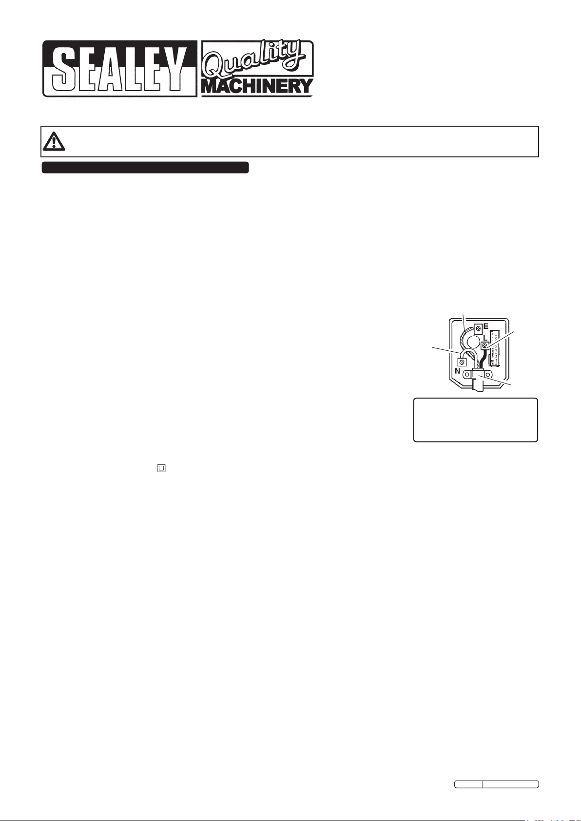
cut off and fit a new plug according to the following instructions (discard old plug safely).
(UK only - see diagram at right). Ensure the unit is correctly earthed via a three-pin plug.
a) Connect the GREEN/YELLOW earth wire to the earth terminal ‘E’.
b) Connect the BROWN live wire to live terminal ‘L’.
c) Connect the BLUE neutral wire to the neutral terminal ‘N’.
After wiring, check that there are no bare wires, that all wires have been correctly
connected, that the cable outer insulation extends beyond the cable restraint and that the restraint is tight.
Double insulated products are often fitted with live (BROWN) and neutral (BLUE) wires only. Double insulated products are always
marked with this symbol . To re-wire, connect the brown and blue wires as indicated above. DO NOT connect the brown or
blue to the earth terminal.
1.1.10. Some products require more than a 13 amp electrical supply. In such a case, NO plug will be fitted. You must contact a qualified
electrician to ensure a 30 amp fused supply is available. We recommend you discuss the installation of a industrial round pin plug and
socket with your electrician.
1.1.11. Cable extension reels. When a cable extension reel is used it should be fully unwound before connection. A cable reel with an RCD
fitted is recommended since any product which is plugged into the cable reel will be protected. The section of the cores in the cable
reel is important. Use 1.5mm² section cable as a minimum but to be absolutely sure that the capacity of the cable reel is
suitable for this product and for others that may be used in the other output sockets, we recommend the use of 2.5mm² section cable.
1.2 GENERAL SAFETY
Familiarise yourself with the application, limitations and potential hazards of the machine.
WARNING! Ensure all Health and Safety, local authority, and general workshop practice regulations are strictly adhered to.
WARNING! Disconnect from the mains power supply before changing accessories, servicing or performing any maintenance.
WARNING! DO NOT sand any materials containing asbestos.
Maintain the machine and keep in good condition (use an authorised service agent).
Check the alignment of moving parts regularly. For safest performance keep the machine clean at all times.
Before each use check all abrasive attachments for condition. If worn or damaged replace immediately.
Replace or repair damaged parts. Use recommended parts only. Unauthorised parts are dangerous and will invalidate the warranty.
Locate the machine in a suitable area. Keep area clean, uncluttered and ensure there is adequate lighting.
Ensure the machine is situated on a solid work surface, adequate for supporting the weight of the machine and the workpiece.
Ensure there are no flammable or combustible materials near the work area.
Remove ill fitting clothing, ties and loose jewellery, and tie back long hair.
Maintain correct balance and footing, ensure the floor is not slippery and wear non-slip shoes.
Keep hands and body clear of the worktable when operating the machine.
Wear approved safety eye or face protection when operating the machine. If dust is generated respiratory protection must be worn.
DO NOT operate the machine when you are tired or under the influence of alcohol, drugs or intoxicating medication.
DO NOT leave the machine running unattended.
DO NOT touch the abrasive whilst operating, or whilst sander is plugged into the mains power.
DO NOT switch the machine on while the workpiece is in contact with the abrasive.
DO NOT operate the machine if any parts are damaged or missing as this may cause failure or possible personal injury.
DO NOT allow children or untrained persons to operate the machine. Keep them away from the work area.
DO NOT use the machine for any purpose other than wood finishing.
When not in use unplug from the mains power supply and make every effort to ensure the machine is childproof.
Original Language Version
Blue
Neutral
Wire
Yellow & Green
Earth Wire
Brown
Live
Wire
Cable
Restraint
FUSE RATING
THIS PRODUCT MUST BE
FITTED WITH A
13 AMP FUSE
SM1301 Issue: 2 - 23/03/10
Page 2
1.3. LEAD PAINT WARNING!
Paint once contained lead as a traditional ingredient. Contact with the dust from the removal of such paint is toxic and must therefore be
avoided. The following action must be taken before using the sander on a surface that you suspect may contain lead paint.
1. User must determine potential hazard relating to age of paint to be removed (modern paints do not have lead content).
2. DANGER! Keep all persons and pets away from the work area.
3. We recommend personal protection by using the following safety items:
a) Paint Spray Respirator (Our ref SSP16EN)
b) PE Coated Hooded Coverall (Our ref SSP266).
c) Latex Gloves (Our ref SSP24).
4. Take adequate measures to contain the paint dust, flakes and scrapings.
5. Continue to wear safety equipment as in (3) above and thoroughly clean all areas when task is complete. Ensure paint waste is disposed
of, in sealed bags or containers, according to local regulations.
2. TECHNICAL SPECIFICATION
Maximum Bobbin Height Above Table: ...................110mm
Maximum Length of Bobbins: ..........................140mm
Oscillating Stroke: ....................................24mm
Oscillations: ........................................24opm
Table Tilt: ........................................... 0-45°
Table Size: ....................................370 x 370mm
Work Table Height:...................................475mm
Speed: ...........................................1400rpm
Dust Extraction Ø: ....................................50mm
Bobbins Included: ................19 x 90, 38 x 140, 50 x 140mm
Bobbins Optional: ..............25 x 90, 44 x 140, 76.2 x 140mm
Motor:.................................... 230V 50Hz 370W
Weight:............................................ 30.7kg
3. ASSEMBLY
3.1. Install Rubber Feet
3.1.1. The sander comes ready assembled apart from the rubber feet.
3.1.2. Fit the feet to the four mounting points on the underside of the sander and secure with the four
nuts and bolts.
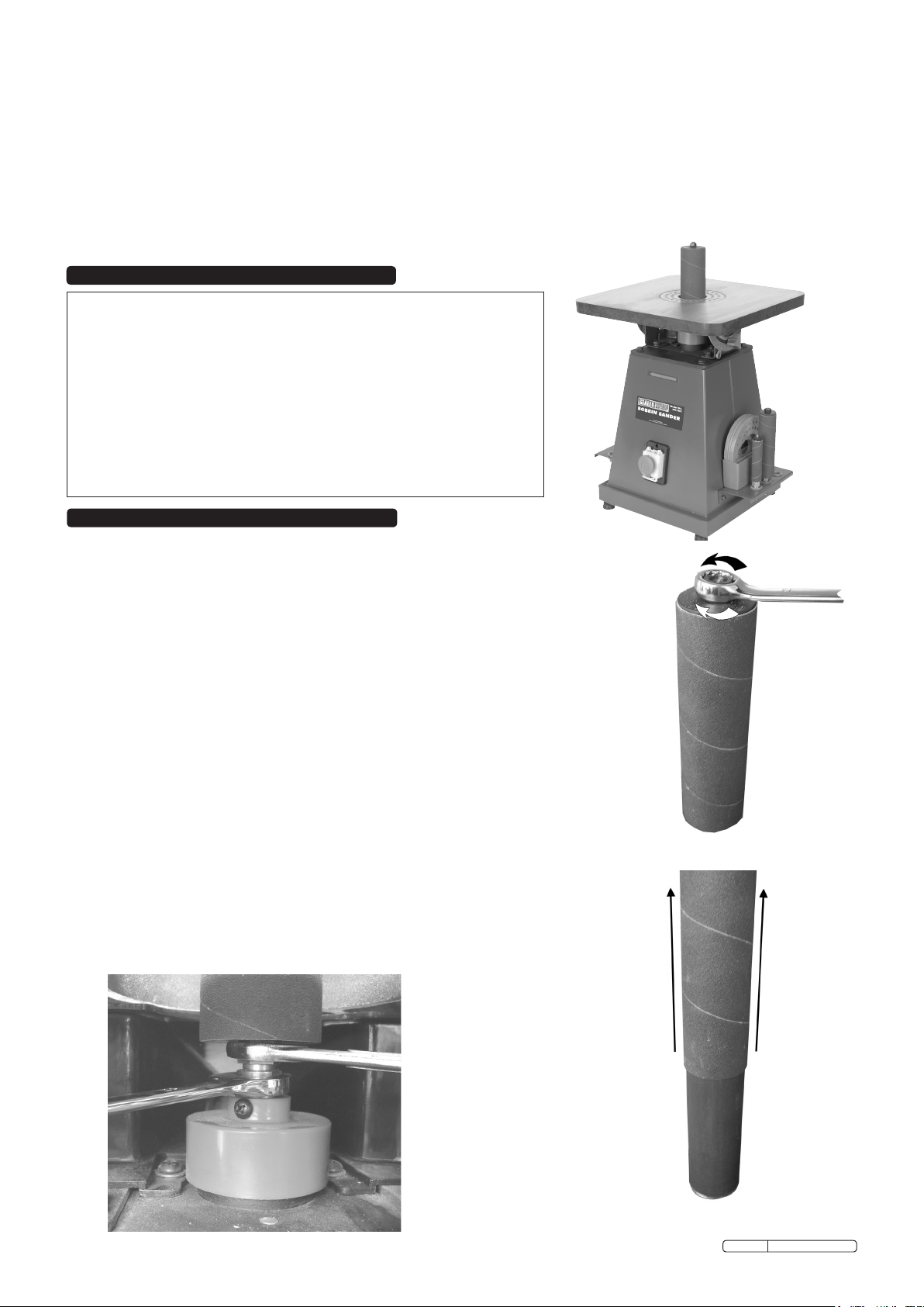
3.2. Fit Sandpaper to Bobbin
3.2.1. Undo the nut (Fig 1) securing the sandpaper cylinder. Note! It has a left-hand thread.
3.2.2. Remove the nut and withdraw the sandpaper (Fig 2).
3.2.3. Slide the new sandpaper cylinder on and replace the nut. The rubber bobbin expands as you
tighten the nut and grips the sandpaper cylinder.
3.3. Fit Bobbin to Machine
3.3.1. Lower the bobbin through the hole in the top of the machine.
3.3.2. Locate the bobbin spindle thread into the motor drive spindle.
3.3.3. Using two spanners tighten the chuck (Fig 3) until the bobbin is firmly held in place. Do not
over-tighten.
3.4. Fit Table Insert
3.4.1 The SM1301 is supplied with two table inserts for each bobbin, one with a round cutout and one
with an oval cutout. For normal sanding with the table flat use the insert with the round cutout.
For sanding with the table at an angle use the insert with an oval cutout.
3.4.2. The table inserts have a small cutout on the edge to enable them to locate with the peg on the
table.
3.4.3. To remove an insert simply push from underneath the table.
3.5. Check Table Top for Level
3.5.1. The table may be tilted through 45°.
3.5.2. To check the table is set at 0° use a 90° set square between the table top and the bobbin.
3.5.3. If it is not square locate the stop bolt on the underside of the table above the degree plate.
3.5.4. Adjust the stop bolt until the table is at 90° with bobbin and tighten locknut on the stop bolt.
3.5.6. Slacken the screw on the degree pointer and align with the zero mark. Tighten screw.
Fig 1
Fig 3
Original Language Version
Fig 2
SM1301 Issue: 2 - 23/03/10
Page 3

4. OPERATING INSTRUCTIONS
4.1. Ensure that you have read, understand and apply the safety instructions in Section 1.
WARNING! Before use, the machine must be positioned on a stable, fireproof bench or table which is strong enough to take
the weight of the machine and the workpiece. Failure to comply with this instruction could result in severe personal injury.
WARNING! Before each use rotate the bobbin by hand to check it is undamaged and secure.
Remove any spanners before turning the machine on. Ensure you wear approved safety goggles, gloves, ear defenders and,
if the machine generates dust, respiratory protection.
WARNING! DO NOT switch the machine on whilst the workpiece is in contact with the bobbin.
4.2. Table adjustment
4.2.1. The table is adjustable through 45O by slackening the two thumb screws on either side of the table and moving the table to the
desired position on the degree plate. Re-tighten the thumb screws.
NOTE! When using the table at an angle ensure you use the insert with the oval hole.
4.3. Starting Sander
4.3.1. The SM1301 is fitted with a No-Volt switch. In the event of a power failure the machine will not start once the power is restored.
4.3.2. The ON/OFF button is located on the front of the machine and incorporates the emergency stop button.
4.3.3. Press the green button to start.
4.3.4. To turn off simply push the emergency stop button, there is no need to lift the cover to access the red stop button.
4.4. Using the SM1301
4.4.1. The bobbins spins clockwise as you look from the front of the machine.
4.4.2. Feed the workpiece across and with the direction of the rotation.
CAUTION! Never stand with your body directly behind the workpiece, the machine could force the workpiece into the
operator and cause serious injury.
4.5. Using Table at Angle
4.5.1. Remove the round insert and store. Place the oval insert in the table ensuring it is the correct size to suit the bobbin.
4.5.2. Tilt the table to the desired angle.
4.5.3. Feed the work into the machine following the direction of rotation.
NOTE! When the table is tilted the workpiece must be run parallel to the bobbin for the angle to remain constant.
4.6. Dust Extraction
4.6.1 The SM1301 is fitted with a 50mm extraction outlet which should be connected to a suitable extractor.
4. OPERATING INSTRUCTIONS 5. MAINTENANCE
5.1. Clean regularly using a vacuum cleaner and brush.
5.2. Check machine for defects before every operation.
5.3. Check operation of emergency stop before each use.
5.4. Have the machine regularly serviced by an authorised service agent.
NOTE: It is our policy to continually improve products and as such we reserve the right to alter data, specifications and component parts without prior notice.
IMPORTANT: No liability is accepted for incorrect use of this product.
WARRANTY: Guarantee is 12 months from purchase date, proof of which will be required for any claim.
INFORMATION: For a copy of our latest catalogue and promotions call us on 01284 757525 and leave your full name and address, including postcode.
Sole UK Distributor, Sealey Group,
Kempson Way, Suffolk Business Park,
Bury St. Edmunds, Suffolk,
IP32 7AR
Original Language Version
01284 757500
01284 703534
www.sealey.co.uk
Web
sales@sealey.co.uk
email
SM1301 Issue: 2 - 23/03/10
Page 4

PARTS DIAGRAM & LIST FOR:
BOBBIN SANDER
Issue: 1
Date: 070606
Model:
SM1301
NOTE: It is our policy to continually improve products and as such we reserve the right to alter data, specifications and component parts without prior notice.
IMPORTANT: No liability is accepted for incorrect use of this product.
WARRANTY: Guarantee is 12 months from purchase date, proof of which will be required for any claim.
INFORMATION: For a copy of our catalogue and latest promotions call us on 01284 757525 and leave your full name, address and postcode.
Sole UK Distributor
Sealey Group,
Bury St. Edmunds, Suffolk.
01284 757500
01284 703534
www.sealey.co.uk
Web
sales@sealey.co.uk
email
SM1301 - 1 - 060606
 Loading...