

Page 1

INSTRUCTIONS FOR:
POWER BELT SANDER
MODEL NO: SM100
Thank you for purchasing a Sealey product. Manufactured to a high standard this product will, if used according to these instructions and
properly maintained, give you years of trouble free performance.
IMPORTANT: PLEASE READ THESE INSTRUCTIONS CAREFULLY. NOTE THE SAFE OPERATIONAL REQUIREMENTS, WARNINGS, AND
CAUTIONS. USE THIS PRODUCT CORRECTLY, AND WITH CARE FOR THE PURPOSE FOR WHICH IT IS INTENDED. FAILURE TO DO SO MAY
CAUSE DAMAGE AND/OR PERSONAL INJURY AND WILL INVALIDATE THE WARRANTY.
1. SAFETY INSTRUCTIONS
1.1 ELECTRICAL SAFETY
WARNING! It is the responsibility of the owner and the operator to read, understand and comply with the following:
You must check all electrical products, before use, to ensure that they are safe. You must inspect power cables, plugs, sockets and
any other connectors for wear or damage. You must ensure that the risk of electric shock is minimised by the installation of
appropriate safety devices. A Residual Current Circuit Breaker (RCCB) should be incorporated in the main distribution board. We also
recommend that a Residual Current Device (RCD) is used. It is particularly important to use an RCD with portable products that are
plugged into a supply which is not protected by an RCCB. If in any doubt consult a qualified electrician. You may obtain a Residual
Current Device by contacting your Sealey dealer.
You must also read and understand the following instructions concerning electrical safety.
1.1.1 The Electricity at Work Act 1989 requires that all portable electrical appliances, if used on business premises, are tested by a qualified
electrician, using a Portable Appliance Tester (PAT), at least once a year.
1.1.2 The Health & Safety at Work Act 1974 makes owners of electrical appliances responsible for the safe condition of those appliances
and the safety of the appliance operators. If in any doubt about electrical safety, contact a qualified electrician.
1.1.3 Ensure that the insulation on all cables and on the appliance is safe before connecting it to the power supply. See 1.1.1 and 1.1.2
and use a Portable Appliance Tester.
1.1.4 Ensure that cables are always protected against short circuit and overload.
1.1.5 Regularly inspect power supply cables and plugs for wear or damage and check all
connections to ensure that none is loose.
1.1.6 Important: Ensure that the voltage marked on the appliance matches the power supply
to be used and that the plug is fitted with the correct fuse - see fuse rating at right.
1.1.7 DO NOT pull or carry the appliance by the power cable.
1.1.8 DO NOT pull the plug from the socket by the cable.
1.1.9 DO NOT use worn or damaged cables, plugs or connectors. Immediately have any faulty
item repaired or replaced by a qualified electrician. When a BS 1363/A UK 3 pin plug is
Blue
Neutral
Wire
damaged, cut the cable just above the plug and dispose of the plug safely.
Fit a new plug according to the following instructions (UK only).
a) Connect the GREEN/YELLOW earth wire to the earth terminal ‘E’.
b) Connect the BROWN live wire to the live terminal ‘L’.
c) Connect the BLUE neutral wire to the neutral terminal ‘N’.
d) After wiring, check that there are no bare wires, that all wires have been correctly connected, that the cable outer insulation extends
beyond the cable restraint and that the restraint is tight. Double insulated products, which are always marked with this symbol , are
fitted with live (brown) and neutral (blue) wires only. To rewire, connect the wires as indicated above - DO NOT connect either wire to
the earth terminal.
1.1.10 Products which require more than 13 amps are supplied without a plug. In this case you must contact a qualified electrician to ensure
that a suitably rated supply is available. We recommend that you discuss the installation of an industrial round pin plug and socket
with your electrician.
1.1.11 If an extension reel is used it should be fully unwound before connection. A reel with an RCD fitted is preferred since any appliance
plugged into it will be protected. The cable core section is important and should be at least 1.5mm², but to be absolutely sure that the
capacity of the reel is suitable for this product and for others which may be used in the other output sockets, we recommend the use
of 2.5mm² section cable.
1.2 GENERAL SAFETY
Disconnect the sander from the mains power before changing accessories, servicing or performing any maintenance.
Maintain sander and belts in good condition. Check moving parts and alignment. If necessary use an authorised service agent.
Replace or repair damaged parts. Use genuine parts only. Unapproved parts may be dangerous and will invalidate the warranty.
WARNING! Always work with the sander safety guard in place.
Wear approved safety goggles, ear defenders, appropriate dust mask if sander generates dust and safety gloves.
Remove ill fitting clothing. Remove ties, watches, rings, and other loose jewellery, and contain long hair.
Use sander in a suitable work area, keep area clean, tidy and free from unrelated materials, and ensure adequate lighting.
Maintain correct balance and footing. DO NOT over-reach and ensure the floor is not slippery. Wear non-slip shoes.
Check grinding disc to ensure they are not split, cracked or damaged in anyway. See chapter 4. If in doubt to not use the disc.
Grinding discs must be securely attached before use, but not over tightened.
Secure unstable workpiece with a clamp, vice or other adequate holding device, and ensure the sander is gripped with both hands.
Keep non essential persons away from the working area, use screens if necessary.
DO NOT operate the sander if any parts are missing or the sander is damaged.
DO NOT use the sander for a task it was not designed to perform.
DO NOT operate sander where there are flammable liquids or gasses.
WARNING! DO NOT grind any materials containing asbestos.
DO NOT get the sander wet or use in damp or wet locations.
DO NOT switch the sander on whilst the belt is in contact with the workpiece.
DO NOT touch the workpiece immediately after grinding as it will be very hot.
DO NOT hold unsecured work in your hand, and DO NOT touch the sanding belt whilst operating, or whilst plugged into the mains power.
DO NOT leave the sander running unattended.
DO NOT operate the sander when you are tired or under the influence of alcohol, drugs or intoxicating medication.
When not in use switch sander off, remove plug from power supply and store in safe, dry, childproof area.
Original Language Version
Yellow & Green
Earth Wire
Brown
Live
Wire
Cable
Restraint
FUSE RATI NG 13 AMP
SM100 Issue: 2 - 23/11/09
Page 2
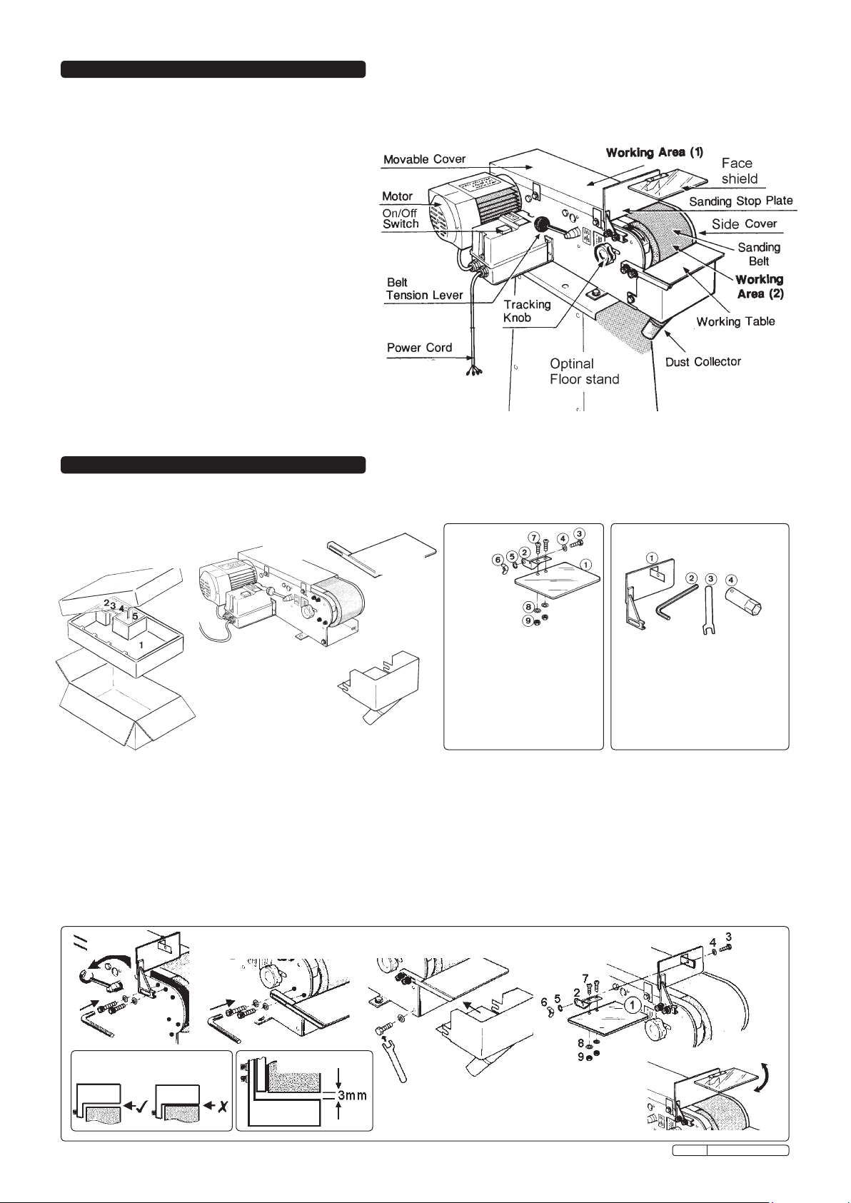
2. DESCRIPTION & SPECIFICATIONS
The SM100 has a heavy cast base with adjustable sanding table. Fitted with magnetic no-volt release switch to prevent accidental starting
should the belt jam. Equipped with a quiet and powerful 230V 1Hp motor, the SM100 is suitable for metal and fabrication workshops.
An optional floor stand is available.
Motor .......................... 0.75kW 1Hp
Power .......................... 230V - 1ph
Sanding belt ..................... 100 x 1220mm
Belt speed ...................... 19m/sec (50Hz)
Driving wheel .................... Ø 126 x 105mm
Flat grinding surface............... 320 x 105mm
Dimensions (LxWxH) .............. 650x380x260mm
Weight ......................... 27.5kg
“A” weighted sound ............... 82.0 dB
“B” weighted sound ............... 81.6 dB
Spare belts available as follows:
SM100/B080G 80 grit sanding belt
SM100/B100G 100 grit sanding belt
Optional stand part number SM100/ST specifications:
Machine height (with stand) ......... 1070mm
Cabinet stand size (LxWxH)......... 380x395x810mm
3. PACKAGE CONTENT & ASSEMBLY
3.1. Package content
Unpack carton as illustrated below and identify each part according to item description. Should there be any damaged or missing parts contact
your supplier immediately.
Carton
with item identification
Item 1
Main body
Item 2
Work table
Face
Shield
Item 4 Sanding stop plate & toolsItem 3
No Description Qty
Item 5
Dust cover
1 Face shield 1
2 Support plate 1
3 Hex bolt 1/4” x 1/2”L 1
4 Washer M6 x18x2 1
5 Spring washer 1/4” 1
6 Wing Nut 1/4” 1
7 Screw 3/16 x 7/16”L 2
8 Washer 3/16”x12x0.8 2
9 Hex nut 3/16” 2
No Description Qty
1 Sanding stop plate 1
2 6mm Hex wrench 1
3 12mm open spanner 1
4 socket wrench 1
3.2 ASSEMBLY
WARNING! Ensure sander has not been connected to mains power supply. Refer to diagrams to assist assembly.
3.2.1 TENSION AND SANDING STOP PLATE
The belt tension has been pre-set by the manufacturer. For shipping purposes the manufacturer has slackened the tension by turning
the tension lever to the “Loosen” position. To re-tension the belt push the lever down toward the “tighten” position (fig 1). Install the
sanding stop plate and ensure that it does not touch the sanding belt see fig 1 & 1a.
3.2.2 WORKING TABLE
Locate working table in correct position (fig 2) Ensure the distance between the working table and the sanding belt is at 3mm (fig 2a).
3.2.3 DUST COLLECTOR
Fit the dust collector unit with washer and bolt on each side (fig 3).
3.2.4 SAFETY FACE SHIELD
Install the face shield and make adjustments to gain the maximum protection (fig 4 & 5).
fig 1
fig 2
fig 3
fig 4
fig 1a
fig 2a
Original Language Version
fig 5
SM100 Issue: 2 - 23/11/09
Page 3

4. SANDING BELT ADJUSTMENT
4.1 TRACKING ADJUSTMENT
WARNING! Ensure mains power lead is unplugged from the mains supply,
4.1.1 Connect the other end of the mains power lead to the sanding machine (fig 6)
4.1.2 Identify the tracking knob (fig 7) each turn of the knob will only render a slight
adjustment to the belt tracking.
4.1.3 Rotate the tracking knob clockwise to move the belt to the left and anti-clockwise to move
belt to the right.
4.1.4 Rotate the belt by hand whilst turning the tracking knob to effect movement.
4.1.5 To ensure the belt is aligned, connect the machine to the mains power supply, turn the machine
“On”, and then “Off”, whilst adjusting the tracking knob to effect further fine adjustments.
Note: “I” = On. “0” = Off.
4.2 BELT TENSION
WARNING! Ensure the sander is switch off and unplugged from the mains power supply.
The belt tension has been pre-set by the manufacturer but will require adjustment after a period
of use or when a new belt is fitted.
4.2.1 Locate cover plate to the right of the tension lever. Loosen screw and open the cover plate (fig 8).
4.2.2 Turn the tension lever to “Loosen”.
4.2.3 Loosen locking nut (fig 9).
4.2.4 To decrease tension turn adjusting rod upward (fig 10).
To increase the tension turn the adjusting rod downward.
Note: One 360° turn on the adjusting rod will move the belt roller in or out by approximately 2.5mm.
We recommend small adjustments are made by turning the adjusting rod only to the degree that access
will allow the spanner to move, and then test the belt tension before making further adjustments.
4.2.5 When complete tighten the locking nut, close and lock the cover plate in place. Turn the belt tension lever
back to the “Tighten” position, and re-check that the belt tracking is correct.
fig 6
fig 7
fig 8
5. OPERATING PRINCIPLE
fig 9
fig 10
5.1 GENERAL
5.1.1 Ensure you have read and understood chapter 1 safety instructions.
5.1.2 Double check that the gap between the worktable and the belt is set at no more than
3mm.
5.1.3 Always start the belt first and bring your workpiece to the moving belt.
DO NOT start the belt whilst the workpiece is resting against the abrasive surface.
5.1.4 Check that there are no foreign bodies in the workpiece which could damage
the sanding belt or cause a hazard. i.e. nails, screws etc.
5.1.5 We recommend you practice with off-cuts of wood to familiarise yourself with
the machines capabilities.
WARNING! do not allow your fingers to touch the surface of the moving belt.
5.2 ROLLER-SANDING
To sand work piece on the roller end of machine, position face guard for maximum
protection and hold the workpiece firmly by hand whilst using the working
table for support (fig 11).
5.3 SURFACE SANDING
For sanding a large flat workpiece, remove the belt cover. Hold workpiece on the flat
surface of the abrasive belt to complete task (fig12).
Use the stop plate to rest work against.
5.4 DUST COLLECTOR
The SM100 is equipped with a dust collector provided with a 35mm Ø outlet
for connection to your own dust extraction system (fig 13).
WARNING! Dust produced by this operation may be hazardous in which case
we recommend the use a face or dust mask.
6. MAINTENANCE
WARNING! Ensure the sander is switched off and unplugged from the mains power
supply.
6.1 OVERLOAD SWITCH
Should the sander motor be overloaded an overload switch will activate cutting the
power to the machine. If this happens allow the motor to cool. The overload switch
is located on the main contactor underneath the switch cover.
6.2 BELT REPLACEMENT
6.2.1 Turn the belt tension lever to “Loosen”.
6.2.2 Remove the two screws in (fig 14), open the belt cover and remove the used belt.
6.2.3 Place the new belt over the end rollers (fig 15).
6.2.4 Re set the belt tension lever by turning it to the “tighten” position.
6.2.5 Rotate the belt by hand whilst checking and adjusting the tracking.
6.2.6 Check and adjust the belt tension accordingly.
fig 14
fig 15
fig 11
fig 12
fig 13
Original Language Version
SM100 Issue: 2 - 23/11/09
Page 4

WARNING! Ensure the sander is switched off and unplugged from the mains power
supply.
6.3 PRIME WHEEL REPLACEMENT
fig 16
6.3.1 Turn the belt tension lever to “Loosen”.
6.3.2 Remove belt cover and remove the belt (fig 16).
6.3.3 Remove motor rear guard (fig 17).
6.3.4 Stop the motor shaft from turning by inserting a screw driver in spindle hole (fig 17).
6.3.5 Place socket wrench (chapter 3 item 4.4) over wheel nut, secure motor spindle whilst
loosening nut (fig 18).
6.3.6 Remove retaining nut and draw the prime roller off centre spindle (fig 19) and
replace with a new wheel reversing the above process to make ready for use.
fig 17 fig 18 fig 19
7. OPTIONAL FLOOR STAND
List of contents
No Description Qty
1 Stand leg (front & rear) 2
2 Stand leg (left & right) 2
3 Stand Top 1
4 Square neck bolt
5/16”-18NCx5/8” 4
5 Hex bolt
5/16” -NCX3/4” 4
6 Washer
5/16”x23/32Dx1/16” 12
7 Spring washer 5/16” 8
8 Hex nut 5/16” -18NC 8
Assembly
1
2
3
NOTE: It is our policy to continually improve products and as such we reserve the right to alter data, specifications and component parts without prior notice.
IMPORTANT: No liability is accepted for incorrect use of this product.
WARRANTY: Guarantee is 12 months from purchase date, proof of which will be required for any claim.
INFORMATION: For a copy of our latest catalogue and promotions call us on 01284 757525 and leave your full name and address, including postcode.
4
Sole UK Distributor, Sealey Group,
Kempson Way, Suffolk Business Park,
Bury St. Edmunds, Suffolk,
IP32 7AR
Original Language Version
01284 757500
01284 703534
www.sealey.co.uk
Web
sales@sealey.co.uk
email
SM100 Issue: 2 - 23/11/09
Page 5

PARTS LIST FOR:
POWER BELT SANDER
MODEL NO: SM100
Issue: ............ 2
Issue Date: ...020305
01284 757500
Sole UK Distributor, Sealey Group, Bury St. Edmunds, Suffolk.
01284 703534
www.sealey.co.uk
Web
email
sales@sealey.co.uk
SM100 - 2 - 280205
Page 6

No. Stock Code Description
1 SM100/001 Hex Bolt
2 SM100/002 Screw
3 SM100/003 Spring washer
4 SM100/004 Dust Proof Cover
5 SM100/005 Base
6 SM100/006 Hex. Bolt
7 SM100/007 Bush
8 SM100/008 Dust Proof Plate
9 SM100/009 Belt Support
10 SM100/010 Arrow Mark
11 SM100/011 Cam
12 SM100/012 Hex Nut- Looseproof
13 SM100/013 Press Block
14 SM100/014 Adjusting Rod
15 SM100/015 Hex. Nut
16 SM100/016 Sliding Block
17 SM100/017 Pin
18 SM100/018 Adjusting Block
19 SM100/019 Spring
20 SM100/020 Spring Stop Plate
21 SM100/021 Upper Support
22 SM100/021 Cap Screw
23 SM100/023 Block Stop Plate
24 SM100/024 Lower Support
25 SM100/025 Movable Cover
26 SM100/026 Aluminium Roller
27 SM100/027 Hex. Nut
28 SM100/027 Rubber Roller
29 SM100/029 Snap Ring
30 SM100/030 Ball Bearing
31 SM100/031 Bush
32 SM100/032 Shaft
33 SM100/033 Snap Ring
34 SM100/034 Sanding Belt
35 SM100/035 Washer
36 SM100/036 Hex. Shaft
37 SM100/037 Protection Cover
38 SM100/038 Hex. Bolt
39 SM100/039 Ball Knob
40 SM100/040 Screw Shaft
41 SM100/041 Cam Shaft
42 SM100/042 Loosen-Tighten Plate
43 SM100/043 Adjusting Plate
44 SM100/044 Cover Screw
45 SM100/045 Wave Washer
46 SM100/046 Cover Plate
47 SM100/047 Cover
48 SM100/048 Tracking Knob
49 SM100/049 Spring
50 SM100/050 Washer
PARTS LIST FOR:
POWER BELT SANDER
MODEL NO: SM100
No. Stock Code Description
51 SM100/051 Cap Screw
52 SM100/052 Washer
53 SM100/053 Working Table
54 SM100/054 Sanding Stop Plate
55 SM100/055 Wing Nut
56 SM100/056 Support Plate
57 SM100/057 Screw
58 SM100/058 Washer
59 SM100/059 Hex. Bolt
60 SM100/060 Dust Collector
61 SM100/061 Eye Shield
62 SM100/062 Washer
63 SM100/063 Hex. Nut
64 SM100/064 Screw
65 SM100/065 Rear Protector
66 SM100/066 Fan
67 SM100/067 Rear Support
68 SM100/068 Ball Bearing
69 SM100/069 Rotor
70 SM100/070 Stator Housing
71 SM100/071 Ball Bearing
72 SM100/072 Front Support
73 SM100/073 Screw
74 SM100/074 Screw
75 SM100/075 Switch Box Cover
76 SM100/076 Switch Box
77 SM100/077 Screw
78 SM100/078 Supporting Plate
79 SM100/079 Screw
80 SM100/080 Strain Relief
81 SM100/081 Power Cord
82 SM100/082 Wiring Box Cover
83 SM100/083 Packing
84 SM100/084 Screw
85 SM100/085 Capacitor Sleeve
86 SM100/086 Running Capacitor
87 SM100/087 Capacitor Cover
88 SM100/088 Plug
89 SM100/089 Plug Socket
90 SM100/090 Packing
91 SM100/091 Wire Connector
92 SM100/092 Wiring Box
93 SM100/093 Screw
94 SM100/094 Int. Washer
95 SM100/095 Packing
96 SM100/096 Screw
97 SM100/097 Copper Set
98 SM100/098 Ext. Washer
99 SM100/099 Strain Relief
100 SM100/100 Screw
SM100
Wiring
diagram
01284 757500
Sole UK Distributor, Sealey Group, Bury St. Edmunds, Suffolk.
01284 703534
www.sealey.co.uk
Web
email
sales@sealey.co.uk
SM100 - 2 - 280205
 Loading...