

Page 1

INSTRUCTION MANUAL FOR:
PowerStart Power Pack
12/24V 6000 Peak Amps
MODEL No: PWRSTART 6000
IMPORTANT: PLEASE READ THESE INSTRUCTIONS CAREFULLY. NOTE THE SAFE OPERATIONAL REQUIREMENTS, WARNINGS AND CAUTIONS.
USE THIS PRODUCT CORRECTLY AND WITH CARE FOR THE PURPOSE FOR WHICH IT IS INTENDED. FAILURE TO DO SO MAY CAUSE DAMAGE
AND/OR PERSONAL INJURY AND WILL INVALIDATE THE WARRANTY. PLEASE RETAIN THESE INSTRUCTIONS FOR FUTURE USE.
Thank y ou for purch asing a Seal ey prod uct.
Manufactured to a high standard this item will give you years of trouble free performance if these instructions are carefully followed and the product is correctly maintained.
1. SAFETY INSTRUCTIONS
Original Language Version
PWRSTART6000 Issue: 2 - 16/05/11
1.1. ELECTRICAL SAFETY
REGARDING DIRECT MAINS POWER USE OF THE
CHARGING UNIT. (See fig.5)
WARNING! It is the responsibility of the owner and the
operator to read, understand and comply with the following:
You must check all electrical products, before use, to ensure
that they are safe. You must inspect power cables, plugs,
sockets and any other connectors for wear or damage. You
must ensure that the risk of electric shock is minimised by the
installation of appropriate safety devices. A Residual Current
Circuit Breaker (RCCB) should be incorporated in the main
distribution board. We also recommend that a Residual
Current Device (RCD) is used. It is particularly important to
use an RCD with portable products that are plugged into a
supply which is not protected by an RCCB. If in any doubt
consult a qualified electrician. You may obtain a Residual
Current Device by contacting your Sealey dealer. You must
also read and understand the following instructions
concerning electrical safety.
1.1.1. The Electricity at Work Act 1989 requires that all portable
electrical appliances, if used on business premises, are tested
by a qualified electrician, using a Portable Appliance Tester
(PAT), at least once a year.
1.1.2. The Health & Safety at Work Act 1974 makes owners of
electrical appliances responsible for the safe condition of
those appliances and the safety of the appliance operators. If
in any doubt about electrical safety, contact a qualified
electrician.
1.1.3. Ensure that the insulation on all cables and on the charger
is safe before connecting it to the power supply. See 1.1.1.
and 1.1.2. and use a Portable Appliance Tester.
1.1.4. Ensure that cables are always protected against short circuit
and overload.
1.1.5. Regularly inspect the power supply cable and plug for wear or
damage and check all connections to ensure that none is loose.
1.1.6. Important: Ensure that the voltage marked on the appliance
matches the power supply to be used and that the plug is
fitted with the correct fuse - see fuse rating at (BELOW) right.
1.1.7. DO NOT pull or carry the appliance by the power cable.
1.1.8. DO NOT pull the plug from the socket by the cable.
1.1.9. DO NOT use worn or
damaged cables,
plugs or connectors.
Immediately have
any faulty item
repaired or replaced
by a qualified
electrician. When a
BS 1363/A UK 3 pin
plug is damaged, cut
the cable just above
the plug and dispose
of the plug safely.
Fit a new plug
according to the
following instructions (UK only).
a) Connect the GREEN/YELLOW earth wire to the earth
terminal ‘E’.
b) Connect the BROWN live wire to the live terminal ‘L’.
c) Connect the BLUE neutral wire to the neutral terminal ‘N’.
d) After wiring, check that there are no bare wires, that
all wires have been correctly connected, that the cable
outer insulation extends beyond the cable restraint and
that the restraint is tight.
Double insulated products, which are always marked with
this symbol , are fitted with live (brown) and neutral (blue)
wires only. To rewire, connect the wires as indicated in diagram.
DO NOT connect either wire to the earth terminal.
1.2. GENERAL SAFETY
Read the vehicle handbook to check for any specific battery
charging information.
This unit must only be used on systems running on 12V or
24V only.
This unit is intended for use in emergencies only. Do not use
the starter instead of the vehicle battery. Use it during start-up
operations only.
Avoid contact with battery acid. If an operator comes into
contact with the acid, rinse affected parts immediately under
clean running water. Continue to rinse the area until medical
help arrives.
Wear approved safety eye protection i.e. goggles (standard
spectacles are not adequate).
WARNING!Ensure that there are no sources of flammable
ignition near the work area i.e. naked flames, cigarettes, flame
heaters, etc. as lead acid batteries produce explosive gases.
DO NOT allow the starter terminal clamps to touch each
other when the power is on. Remember that gases are
produced which may ignite if sparks occur. To minimise
accidental contact, disconnect the mounting socket (12V/24V)
from the starter panel and place the battery clamps in the
storage pocket on the front of the unit.
WARNING! Ensure that the work area is well ventilated as the
gases produced are flammable.
DO NOT work alone. In case of an accident have someone at
hand to help.
Maintain the starter in good condition (use an authorised
service agent only).
Keep the starter clean for best and safest performance.
Locate the starter in a suitable work area and keep the
area clean and tidy and free from unrelated materials. Ensure
adequate lighting.
Remove ill fitting clothing. Remove ties, watches, rings and
other loose jewellery and contain long hair.
WARNING!Disconnect the mains power before servicing or
performing any maintenance.
Disconnect from the mains power before connecting to, or
disconnecting from, the battery.
Clean clamps and battery terminals, removing any oxidation
before connecting the starter to the battery.
Ensure that the correct polarity clamp is attached to the
correct terminal of the battery. POSITIVE is indicated by (+)
and may be red, NEGATIVE is indicated by (-) and may be
black. If there are no identifiable symbols, you can
distinguish the NEGATIVE battery terminal as the one which
is connected from the battery directly to the vehicle body.
(For negative earth vehicles only, for positive Earth
vehicles consult the vehicle handbook for the correct
connection procedure.)
DO NOT use any other type of Charger Unit other than the
one supplied to charge the starter unit.
DO NOT use the Charger Unit to charge any other
electrical item.
DO NOT get the Charger Unit wet, or use in wet, damp
conditions (for indoor use only).
DO NOT operate the Charger Unit if it has been dropped, or
has received a sharp knock, or is damaged. Contact an
authorised service agent.
DO NOT try to open or dis-assemble the Charger Unit as this
may cause damage or personal injury and will invalidate your
warranty.
RECOMMENDED FUSE RATING
3 AMP
Blue
Neutral
Wire
Yellow & Green
Earth Wire
Cable
Restraint
Brown
Live
Wire
Page 2
2. INTRODUCTION & SPECIFICATION
3. ASSEMBLY
4. OPERATION
WARNING! Electrical shock can cause death or injury. Avoid
touching exposed conductors of electricity. This unit is designed for
use with vehicle or boats. You will not need a host vehicle or 230VAC
power supply (Except for recharging the unit after use). You can also
use this system as a portable power source of 12VDC in remote
areas or emergencies.
4.1 Using the starter to start a vehicle.
4.1.1 Check that the starter clamps are NOT powered up by
ensuring that the mounting socket (fig.4-1) is disconnected.
4.1.2 Make sure that the ignition switch of the vehicle or boat to be
started is in the OFF position.
4.1.3 Connect the red clamp (+) to the positive terminal on the
vehicle's battery.
4.1.4 Connect the black clamp (-) to a non moving metal part of the
engine, do not connect the clamp to the negative terminal on
the battery.
4.1.5 REVERSE POLARITY WARNING. If the red light shown in
fig.3 comes on together with a buzzer, this is a warning that
there is a reverse polarity situation. Do not connect the
mounting socket to either the 12V or 24V supply until the
clamps are correctly connected as described above.
Keep children and unauthorised persons away from the work
area.
DO NOT use the starter for any purpose other than that
for which it is designed.
DO NOT allow untrained persons to operate the starter.
DO NOT get the starter wet or use in damp or wet
locations or areas where there is condensation.
DO NOT operate the starter if it is damaged.
DO NOT attempt to open or modify the starter.
When not in use store in a safe, dry, child proof area. Store
under lock and key.
DO NOT expose to direct sunlight, heat sources, or humidity.
Ensure that the unit is in a stable position before commencing
use.
Check the condition of cables on a regular basis and if any are
damaged have them repaired or replaced by a qualified
technician.
Before use check for damaged parts and have any faulty
items replaced with authorised parts only. Check that the
cables are securely fastened to the starter.
WARNING!Be vigilant and cautious during the starting
procedure as battery acid is highly corrosive and gases
can be emitted during the starting process that are flammable
and harmful to health.
Avoid electric shocks. Be very cautious when attaching the
clamps to non-insulated conductors or bus bars. Avoid all
body contact with the surfaces of tubes, radiators and metal
power substations while testing the voltage.
g.2
g.1
3.1 ASSEMBLY.
3.1.1 HANDLE MOULDING. Attach the handle moulding to the top
of the unit as shown in fig.1 using the four M6 x 50mm bolts
provided.
3.1.2 WHEELS. Lower the unit carefully onto its front face on a
clean, non abrasive surface.
3.1.3 Slide the chrome axle tube (A) through the holes in the rear
lower corners of the cabinet so that it projects equally either
side.
3.1.4 Place a washer (B) onto each end of the axle followed by a
wheel (C).
3.1.5 Firmly press a plastic plug (D) into each open end of the axle
to retain all components.
3.1.6 FRONT CASTOR. Attach the front castor to the raised plate
on the underside of the unit using the four self tapping screws
provided. Do not over tighten.
3.1.7 Lift the unit into the upright position.
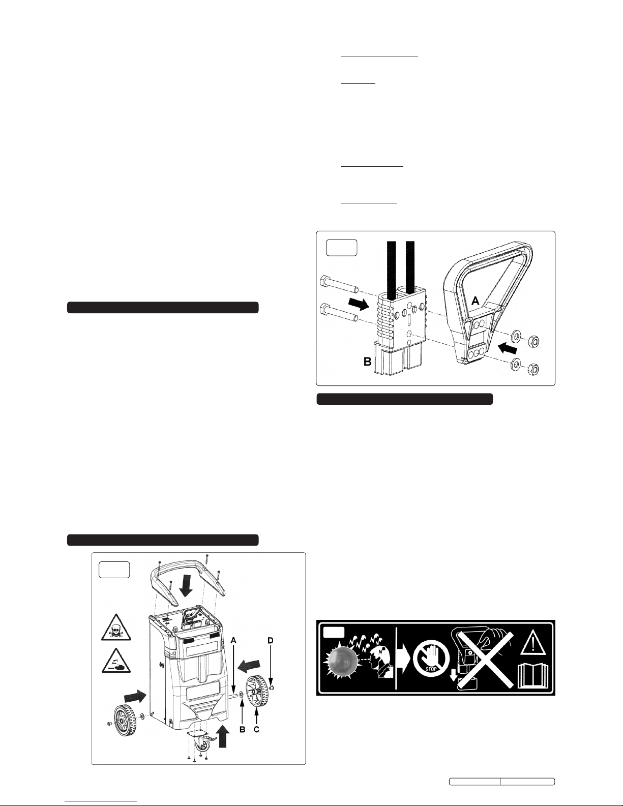
3.1.8 PLUG HANDLE. Referring to fig.2 attach the handle (A) to the
cable plug (B) in the orientation shown using the nuts, bolts
and washers provided.
4.1.6 When no buzzer sounds and the red light is OFF, plug the
mounting socket onto the 12V or 24V supply, according to the
voltage required by the vehicle to be started.
4.1.7 Turn the ignition switch (or key) of the vehicle or boat to ON.
Wait for one minute. Turn the engine over for no more then 5
to 6 seconds. If the vehicle or boat engine does not start, wait
at least 3 minutes before retrying.
g.3
Original Language Version
DESCRIPTION.
Heavy-duty steel case with composite front storage panel.
Features a high powered manufactured battery making this
model suitable for starting most vehicles. Electronic power
switch with LED indicators and 19mm digital voltage display
reduces risk of inadvertent damage by over-voltage. Heavy duty copper cables provide efficient power transfer. Built in trip
to prevent damage to battery or internal circuitry. Surge and
spike suppressing circuitry reduces risk of damaging vehicle’s
on-board electronics. Supplied with mains voltage recharging
pack. Supplied with two heavy-duty rear wheels and one
heavy-duty front locking castor for easy manoeuvrability.
Model No: .................................................. PWRSTART6000
Output Voltage ............................................................ 12/24V
Maximum Engine Size ..................................................600hp
Peak Amps 12V ........................................................... 6000A
Peak Amps 24V ........................................................... 3000A
Cranking Current (20º 5secs) 12V: .............................. 2000A
Cranking Current (20º 5secs) 22V: ................................ 900A
Cold Cranking Current (-18ºC 30secs) 12V: .................. 450A
Cold Cranking Current (-18ºC 30secs) 24V: .................. 350A
Cable size ................................................................... 25mm²
PWRSTART6000 Issue: 2 - 16/05/11
Page 3

WARNING! Never allow the red and black clamps to
touch each other or a common conductor.
4.1.8 When engine is running, always disconnect the starter in the
following order:
1. Disconnect the mounting socket from the starter (starter OFF).
2. Disconnect the black (negative) clamp from the vehicle.
3. Disconnect the red (positive) clamp from the vehicle.
4. Return the clamps to their housing.
NOTE! Recharge the starter as soon as possible.
4.2 Using the starter as a 12V power supply.
4.2.1 Fold back the protective rubber plug from the accessory
socket (fig.4-8).
4.2.2 Insert the accessory plug of the appliance to be powered into the
socket.
4.2.3 Incase of overload the re-settable safety switch will trip. (fig.4-7)
Investigate and remedy the cause of the overload before
pushing the reset button.
4.3 Recharging the starter.
IMPORTANT! To protect the battery and lengthen its
working life, charge it for 12 hours before using it for the
first time, then after every time it is used, and in any case, at
least every three months.
4.3.1 Recharge the unit using the 230V AC power adaptor supplied.
See fig.5. We recommend keeping the batteries fully charged at
all times. A low charge level could shorten the life of the battery.
Bear in mind that the time required to recharge the battery will
depend on the number of times it has been used.
WARNING: Use the supplied charger only and exclusively to
charge the starter.
4.3.2 Insert the charger mains plug (see fig.5) into the mains supply.
4.3.3 Insert the charger output plug (see fig.5) into the charging socket on
the control panel. See fig.4-6.
4.34 The charge level LEDs (fig.4-4) will light up in succession to indicate
that the unit is being charged.
4.3.5 Check the battery charge level by pressing the 'TEST' button
(fig.4-5). The 3 digit display (fig.4-3) indicates the battery voltage
and the bank of 6 bar type LEDs below the display indicates the
charge level (fig.4-4). The 3 digit display will show the 12 volt
reading first. Repeated presses of the test button will toggle the
display between the 12 and 24 volt readings, indicated by the
two single leds at the left hand side of the test button.(fig.4-5).
4.3.6 When 'END' is shown on the display the charging process is
complete. Now unplug the charger from the unit and the mains plug
from the mains supply.
NOTE: The starter has a device for monitoring the charge status of the
batteries. When charging is complete the charger automatically
resets itself and can therefore remain connected for as long as
desired.
4.3.7 The charging system is electronically controlled. The factory
settings for the electronics board are suitable for recharging the
AGM lead acid batteries contained by the starter. When the
starters internal batteries have come to the end of their
working life they should be replaced with batteries of the same
type and specification.
g.4
g.5
Environmental Protection
Recycle unwanted materials instead of disposing of them as
waste. All tools, accessories and packaging should be sorted,
taken to a recycle centre and disposed of in a manner which is
compatible with the environment. When the product is no
longer required, it must be disposed of in an environmentally
protective way. Contact your local authority for recycling
information.
Battery Removal
At the end of its working life the batteries should be removed
from the unit by a qualified electrician and be disposed
according to local authority guidelines.
WARNING: Do not dispose of by fire. This could result in an
explosion.
Under the Waste Batteries and Accumulators Regulations
2009, Jack Sealey Ltd are required to inform potential
purchasers of products containing batteries (as defined within
these regulations), that they are registered with Valpak’s
registered compliance scheme. Jack Sealey Ltd’s Batteries
Producer Registration Number (BPRN) is BPRN00705.
NOTE: It is our policy to continually improve products and as such we reserve the right to alter data, specifications and component parts without prior notice.
IMPORTANT: No liability is accepted for incorrect use of this product.
WARRANTY: Guarantee is 12 months from purchase date, proof of which will be required for any claim.
INFORMATION: For a copy of our latest catalogue and promotions call us on 01284 757525 and leave your full name and address, including postcode.
01284 757500
01284 703534
sales@sealey.co.uk
Sole UK Distributor, Sealey Group,
Kempson Way, Suffolk Business Park,
Bury St. Edmunds, Suffolk,
IP32 7AR
www.sealey.co.uk
Web
email
Original Language Version
Parts support is available for this product. To obtain a parts listing and/or diagram, please log on to
www.sealey.co.uk, email sales@sealey.co.uk or phone 01284 757500.
PWRSTART6000 Issue: 2 - 16/05/11
 Loading...