

Page 1
INSTRUCTIONS FOR:
WELDING HELMET SOLAR POWERED SHADE 9-13
MODEL Nos: PWH699G, PWH699R, PWH699B
Thank you for purchasing a Sealey Power Product. Manufactured to a high standard this product will,
if used according to these instructions and properly maintained, give you years of trouble free performance.
IMPORTANT: PLEASE READ THESE INSTRUCTIONS CAREFULLY. NOTE THE SAFE OPERATIONAL
REQUIREMENTS, WARNINGS AND CAUTIONS. USE THIS PRODUCT CORRECTLY AND WITH CARE FOR THE
PURPOSE FOR WHICH IT IS INTENDED. FAILURE TO DO SO MAY CAUSE DAMAGE OR PERSONAL INJURY
AND WILL INVALIDATE THE WARRANTY. PLEASE KEEP INSTRUCTIONS SAFE FOR FUTURE USE.
1. SAFETY INSTRUCTIONS
WARNING! THIS HELMET IS NOT SUITABLE FOR USE WITH LASER OR GAS WELDING/CUTTING.
3 Ensure all workshop safety rules, regulations and conditions are complied with when using welding equipment. The helmet
will not offer protection against misuse of workshop tools, equipment, or accessories.
3 Maintain the helmet in good condition and protect cartridge from liquid and dirt contact. Regularly replace the protective lens
and replace any damaged or worn parts. Use genuine parts only. Unauthorised parts may be dangerous and will invalidate
the warranty.
3 Whilst the front cover lense is impact resistant it can break in extraordinary circumstances. Always wear CE approved
safety glasses when using this helmet to provide additional protection against flying particles, splash, spray and
spatter.
3 Ensure the front cover lens is securely in place before use.
3 Fit the helmet and adjust the head band so the helmet will sit as low and near to your face as possible,
3 Use helmet only in temperatures ranging from -10°C to 55°C (14°F to 131°F).
3 Store helmet only in temperatures ranging from -20°C to 70°C (-4°F to 158°F).
3 Remove ill fitting clothing, remove ties, watches, rings and other loose jewellery.
3 Maintain correct balance and footing.
3 Ensure the floor is clear from obstructions, not slippery and wear non-slip shoes.
3 Keep children and unauthorised persons away from the working area.
WARNING! The helmet will only protect the eyes and face from radiation and sparks. It will not protect against explosive
devices or corrosive liquids.
7 DO NOT use helmet for any other purpose, other than face protection when grinding.
7 DO NOT use helmet unless you have been instructed in its use by a qualified person.
7 DO NOT open or tamper with the shade cartridge.
7 DO NOT get the helmet wet or use in damp or wet locations.
7 DO NOT leave work place with helmet in lowered position, as bright light source may darken cartridge unexpectedly.
7 DO NOT place the helmet on a hot surface.
7 DO NOT use helmet without front cover lens fitted. To do so will invalidate your warranty.
3 Clean helmet (see section 5.4) and store the helmet in a safe, dry, childproof location.
WARNING! The materials of the helmet may, when coming into contact with the wearers skin, cause an allergic reaction to
susceptible individuals.
WARNING! Before welding always inspect the cartridge filter to ensure that it is not damaged. To test the filter prior to
welding, direct the front of the cartridge filter to a bright light source which will cause the lens to darken. Then using your
hand rapidly cover and uncover the sensor. The filter should lighten momentarily then return to a dark state.
WARNING! DO NOT use the helmet if damaged or you suspect it may be faulty. (Contact your Sealey dealer).
DANGER! DO NOT USE if, at any time, the face plate in the cartridge FAILS to darken
when exposed to a welding spark. Remove cartridge and return to your Sealey dealer for
inspection. Continued use of the product knowing that the auto darkening feature is
NOT FUNCTIONING may DAMAGE YOUR EYES and CAUSE BLINDNESS.
2. INTRODUCTION
High quality lenses with large viewing area
manufactured and tested to BSEN379. Variable
shade from 9-13. Fully automatic switching from light
to dark on striking arc. Fitted with solar power panel no batteries required. PWH699 features infinitely
adjustable sensitivity and delay switches. PWH699
Range has a special grinding feature enabling the
user to grind without having to remove the mask, still
offering a full face protection. All models feature
deluxe contoured helmets approved to BSEN175
which give full neck protection and protects lens from
scratching when helmet is laid down. Comfortable
headband and non-slip quick release ratchet
mechanism. Suitable for MIG and arc welding.
Original Language Version
PWH699 Issue No.1 05/11/09
Page 2
3. SPECIFICATION
PWH699G ................................................Colour Grey
PWH699R .................................................Colour Red
PWH699B ................................................Colour Blue
Shade Active: ........................................9 - 13 Variable
Shade Inactive: ........................................................... 4
Viewing Area: .............................................98 x 47mm
UV/IR Protection: ........ Up to Shade DIN16 at all times
Light/Dark: ........................................................ 0.04ms
Temperature Range: ............................. -10°C to +55°C
Power: ........................................................ Solar Cells
Grinding ..................................................................YES
4. INSTRUCTIONS FOR USE
WARNING! Before using the helmet for welding ensure you
have read and understood the safety instructions in Section 1.
4.1 The helmet comes ready assembled but before it can be
used it must be adjusted to fit the user properly.
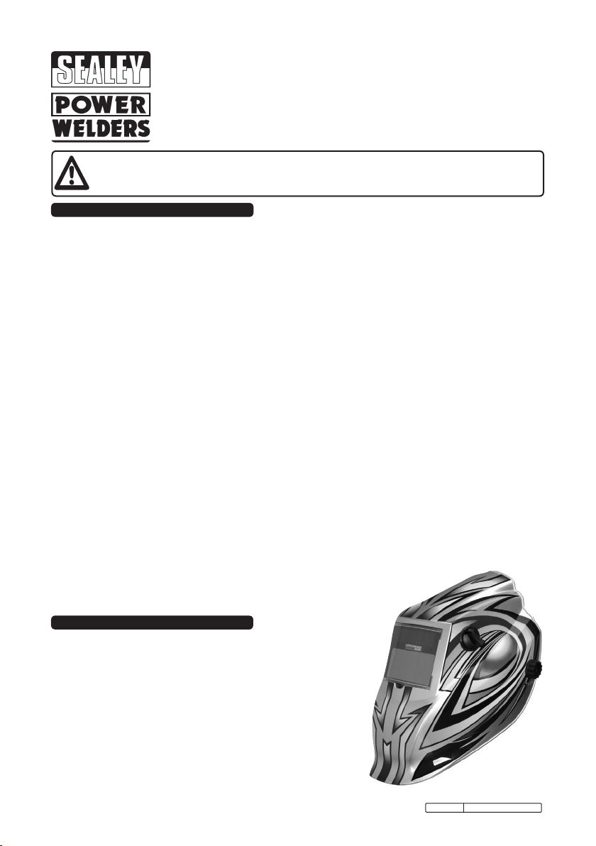
4.2 ADJUSTING THE FIT OF THE HELMET.
The overall circumference of the headband can be made
larger or smaller by pushing in and rotating the knob on the
back of the headband (See adjustment ‘A’ in fig.1). This
can be done whilst wearing the helmet and allows just the
right tension to be set to keep the helmet firmly on the
head without it being too tight.
4.3 If the headband is riding too high or too low on your head
adjust the strap which passes over the top of your head. To
do this release the end of the band by pushing the locking
pip out of the hole in the band. Slide the two portions of the
band to a greater or lesser width as required and push the
locking pip through the nearest hole (See adjustment ‘B’ in
fig.1).
4.4 Test the fit of the headband by lifting up and closing down
the helmet a few times whilst wearing it. If the headband
moves whilst tilting re-adjust it until it is stable.
4.5 ADJUSTING DISTANCE BETWEEN HELMET & FACE.
To adjust the distance between the helmet and your face in
the down position loosen the tilt knobs (D) on either side of
the helmet and slide it nearer to or further from your face.
(See adjustment ‘C’ in fig.1) It is important that your eyes
are each the same distance from the lens otherwise the
darkening effect may appear uneven. Re-tighten the tilt
knobs when adjustment is complete.
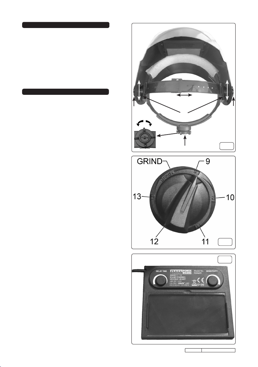
4.6 SELECTING DELAY TIME/RESPONSE TIME
The delay time in which it takes the lens to change from
dark to light or vice versa can be varied from 0.1sec to 1
sec, this adjustment is carried out by turning the delay time
knob on the inside of the lens (see fig.3).
4.7 SENSITIVITY
4.7.1 For normal ambient light conditons set the sensitivity knob
to the high setting (fig.3).
4.7.2 For conditions where there is an excess of light, which may
affect the performance of the lens, turn the knob to the low
setting.
4.8 SELECTING SHADE LEVEL
Refer to the shade guide in Section 7 and adjust the knob
on the side of the helmet to the correct setting (fig.2).
4.9 SELECTING THE GRIND OPTION
When the shade knob is turned to the “grind” position the
shade function is turned off allowing a clear view to grind a
weld with the helmet providing face protection. Ensure that
the shade function is turned back on before welding again.
Original Language Version
B
D
C
A
D
fig.1
fig.2
fig.3
PWH699 Issue No.1 05/11/09
Page 3

5. MAINTENANCE
5.1 REPLACING PROTECTIVE LENS COVERS.
The shade cartridge is fitted with two protective lens covers
to protect the inside and outside from weld splatter. Place
your finger or thumb into the recess on the long edge of the
cover lens frame and flex the frame upwards until it releases
from one edge. (See fig.4-C). Remove the protective film
from the new lens. Hook the lens under the side retaining lip
shown at ‘A’ in fig.4. Press on the other side of the frame to
snap it under the edge shown at ‘B’ in fig.4. Use the same
procedure for the inner protective lens cover.
5.2 CHANGING THE SHADE CARTRIDGE.
Pull off the shade adjustment knob from the side of the
helmet and remove the nut holding the potentiometer. The
cartridge is retained by a wire loop clip as shown in fig.5.
Release the front edge of the clip (fig.6-D) from its retaining
lugs (fig.6-E) and hinge it upwards and out of the way. Lift
the shade cartridge out of its frame.
5.3 FITTING NEW CARTRIDGE.
Take the new shade cartridge and place the cartridge into its
retaining frame inside the helmet. Hinge down the wire loop
clip and ensure that the front edge of the loop is properly
retained under the retaining lugs as shown in fig.5. Insert the
potentiometer through the side of the helmet and secure
with the nut. Refit the knob ensuring that the arrow points to
the min and max settings when turned.
5.4 CLEANING.
Clean helmet by wiping with a soft cloth. Clean cartridge
surfaces regularly. Do not use strong cleaning solutions.
Clean sensors and solar cells with methylated spirit using a
clean cloth and wipe dry with a lint-free cloth.
A
B
C
fig.4
fig.5
6. PROBLEM SOLVING
Problem Cause Solution
Irregular darkening or
dimming.
Shade cartridge does
not darken or ickers.
Poor vision.
Slow response. Operating temperature too low.
Welding helmet slips. Headband adjustments incorrect. Refer to section 4.
The headband may have been unevenly set on the two
sides of the helmet (unequal distances from the eyes to
the shade cartridge).
Readjust the distance of the
shade cartridge.
The sensors are soiled or obstructed. Clean.
Front cover lens oiled or damaged. Clean or replace.
Welding current too low. Adjust weld amps.
Operative lenses and/or shade cartridge soiled. Check, clean or replace.
Insufcient background lighting. Adjust light.
Do not use at temperatures
below -10oC (14oF).
Original Language Version
PWH699 Issue No.1 05/11/09
fig.6
Page 4

7. SHADE GUIDE & MARKINGS
SHADE GUIDE
ARC CURRENT (AMPS)
Welding
Process
SMAW 9 10 11 12 13 14
MIG (Heavy) 10 11 12 13 14
MIG (Light) 10 11 12 13 14 15
TIG/GTAW 9 10 11 12 13 14
MAG/CO2 10 11 12 13 14 15
SAW 10 11 12 13 14 15
PAC 11 12 13
PAW 8 9 10 11 12 13 14 15
SMAW - Shielded Metal Arc Welding
MIG (Heavy)- MIG on Heavy Metals PAW- Plasma Arc Welding PAC- Plasma Arc Cutting
SAW- Shielded Semi-Automatic Arc Welding MAG/CO2- Metal Active Gas
0.5 2.5 10 20 40 80 125 175 225 275 350 450
1 5 15 30 60 100 150 200 250 300 400 500
TIG/GTAW- Gas Tungsten Arc Welding MIG (Light)- MIG on Light Alloys
Meaning of the markings on the filter:
4 9 - 13 SEALEY 1 / 3 / 3 / 379
Light state scale no.
Lightest dark state scale no.
Darkest state scale no.
Manufacturers identification.
Optical class.
Diffusion of light class.
Variation in luminence transmittance class.
Number of the applied standard.
Meaning of the markings on the helmet: EN 175 = Number of the applied standard
CE = CE Mark
Parts support is available for this product. To obtain a parts listing and/or diagram, please log on to
www.sealey.co.uk, email sales@sealey.co.uk or phone 01284 757500.
NOTE: It is our policy to continually improve products and as such we reserve the right to alter data, specifications and component parts without prior notice.
IMPORTANT: No liability is accepted for incorrect use of this product.
WARRANTY: Guarantee is 12 months from purchase date, proof of which will be required for any claim.
INFORMATION: For a copy of our latest catalogue and promotions call us on 01284 757525 and leave your full name and address, including postcode.
Sole UK Distributor, Sealey Group,
Kempson Way, Suffolk Business Park,
Bury St. Edmunds, Suffolk,
IP32 7AR
Original Language Version
01284 757500
01284 703534
www.sealey.co.uk
Web
sales@sealey.co.uk
email
PWH699 Issue No.1 05/11/09
 Loading...