

Page 1
INSTRUCTIONS FOR:
HYDRAULIC PULLER SET
1. INTRODUCTION
1.1. INTRODUCTION
The PS981 consists of 3 three-position puller legs with link plates and
a forged steel 2 and 3 leg yoke operated by a 10 ton hydraulic ram.
The ram is also compatible with sets PS980.V2, PS982.V2 & PS985.V2.
The combination of three-position legs and link plates gives
maximum reach and workpiece diameter of 250mm, enabling the set
to be used for a large range of gears, bearings and pulleys.
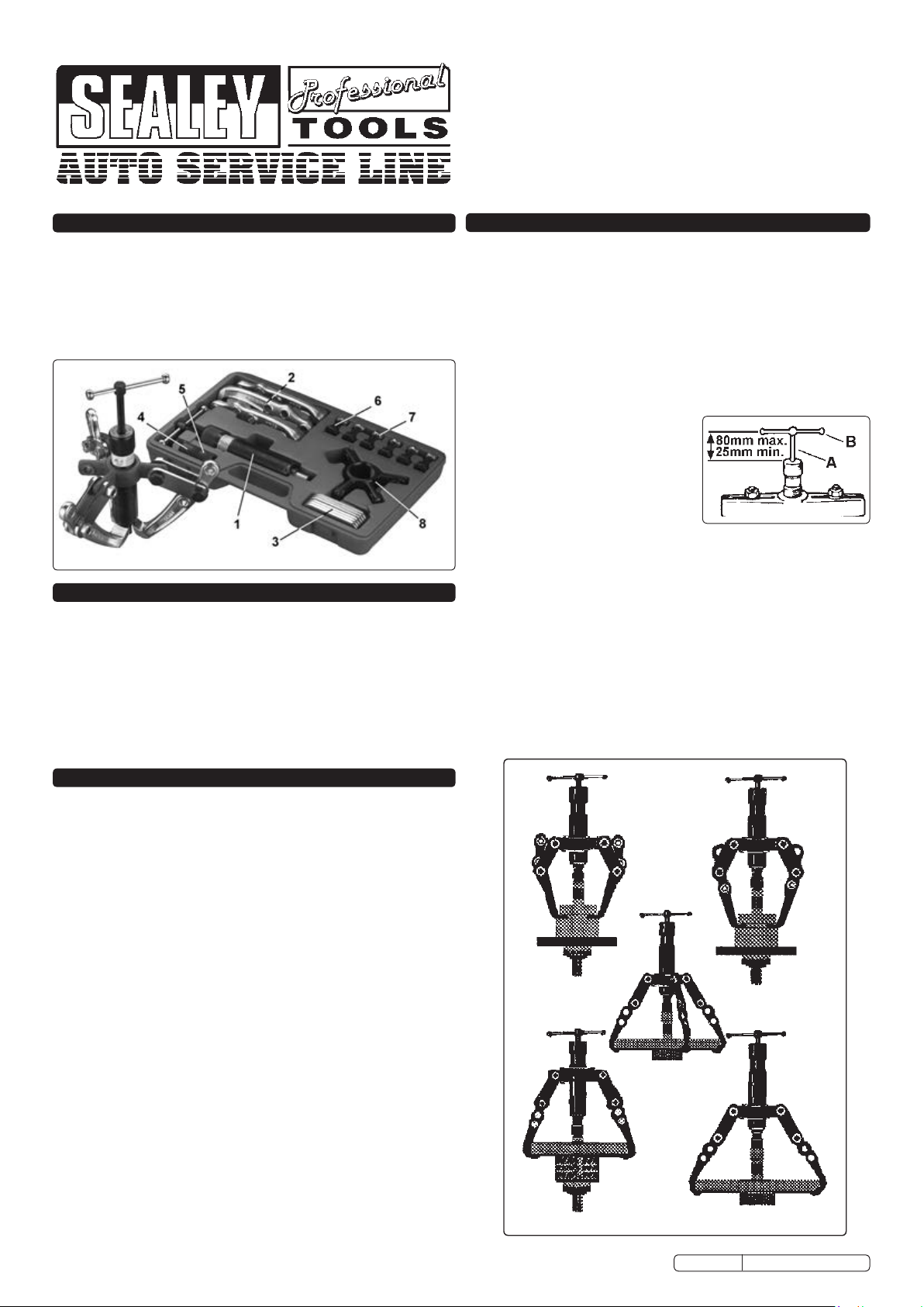
2. CONTENTS & PARTS
Item Part No. Description
1 PS990 Ram 10ton
2 PS981/02 Leg, Combination, 3 off
3 PS981/03 Plate, Steel, 6 off
4 PS981/04 Centre Adaptor
5 PS981/05 Extension (for centre adaptor)
6 PS981/06 Screw and Nut Set
7 PS981/07 Washer, 6 off
8 PS981/08 Support, Ram
PS982/OIL 15grms of oil for single refill. (not shown, not supplied)
PS982.V2-RK Repair Kit for PS990 Ram (not supplied)
PARTS LIST
Issue Date:- 12/05/05
Issue No.:- 3
MODEL NO:
PS981.V2
4. INSTRUCTIONS FOR USE
WARNING! Ensure that you read, understand and apply the
safety instructions in Section 3.
4.1. Confirm that the workpiece is retained by interference fit (parallel
or taper) only.
4.2. Assemble the appropriate puller, see fig.1, and adjust T-
handle (fig.2.A) so that the tommy bar (fig.2.B) is
approximately 80mm (3”) above top of ram, see fig.2.
4.3. Fit the puller claws behind the workpiece and then screw
ram body d own, with centre adaptor (item 4) over piston end,
until centre adaptor point locates in end of shaft from which
workpiece is to be pulled. If necessary use ram extension
(item 5) to achieve this.
Note: Only use centre adaptor
where end of shaft has a
matching ‘centre’ machining.
4.4. Ensure puller is centrally
positioned with respect to
workpiece and shaft and then turn
T-handle clockwise, by hand only,
to pull workpiece from shaft.
4.5. Do not screw T-handle in further than 25mm (1”) from end of the
ram (see fig.2). If workpiece requires additional movement then
unscrew T-handle to 80mm from end of ram, sc rew ram body
down so that centre adaptor again contacts shaft and then
continue to draw workpiece up shaft.
IMPORTANT: The maximum safe load for the puller can be
achieved by hand effort alone. The use of tools or levers on
the tommy bar to increase the load will damage the puller
and may result in injury. Such misuse will also invalidate the
warranty.
WARNING! If the workpiece does not move when maximum
puller force is applied, DO NOT hit it, or the puller, in an
attempt to jar it free. Damage to puller/workpiece and personal
injury may result. Use a larger capacity puller.
fig.2
3. SAFETY INSTRUCTIONS
WARNING! Ensure all Health and Safety, local authority, and
general workshop practice regulations are strictly adhered to
when using tools.
DO NOT use tools if damaged or worn.
Maintain the tools in good and clean condition for best and safest
performance.
Ensure all threads are clean and well lubricated.
Always check that puller is correctly assembled and is square
with the workpiece.
If vehicle is raised, ensure it is adequately supported with axle
stands, ramps, etc. as appropriate.
Wear suitable clothing to avoid snagging. Do not wear jewellery.
Tie back long hair.
Wear approved eye protection. A full range of personal safety
equipment is available from your Sealey dealer.
Where possible shield workpiece with canvas or similar to provide
protection against failed parts.
DO NOT heat puller jaws when heating a gear or bearing as this
will affect the temper and, therefore, the strength of the material.
DO NOT use any tool or lever to turn the ram tommy bar, use
hand effort only.
DO NOT hit workpiece, or ram, with a hammer if workpiece has
not moved with maximum puller force applied. Use a larger capacity
puller.
Account for all tools and parts being used and do not leave them
in or on the vehicle.
IMPORTANT: Always refer to the vehicle manufacturer’s service
instructions, or proprietary manual, to establish the correct
procedure and data. These instructions for use are provided as a
guide only.
fig.1
PS981.V2 ISSUE No:1 05/01/09
Page 2
5. MAINTENANCE
5.1. GENERAL
5.1.1. Keep all items clean and lightly oiled. Keep all threads free from
grit and lubricate the ram regularly.
5.1.2.
Store the ram in the closed position to prevent piston surface corrosion.
5.2. TO CHANGE OIL IN RAM
IMPORTANT: The hydraulic system operates on a specially
formulated oil which must be replaced from time to time.
Use Sealey Hydraulic Jack Oil, available from your
authorised Sealey dealer. Quote model number:
HJO500MLS for 1 x 500ml bottle or PS982/OIL for 15grms
of oil for a single refill.
WARNING! Use of any other oil in ram may cause ram to
fail and will invalidate your warranty. Wear appropriate eye,
face and hand protection.
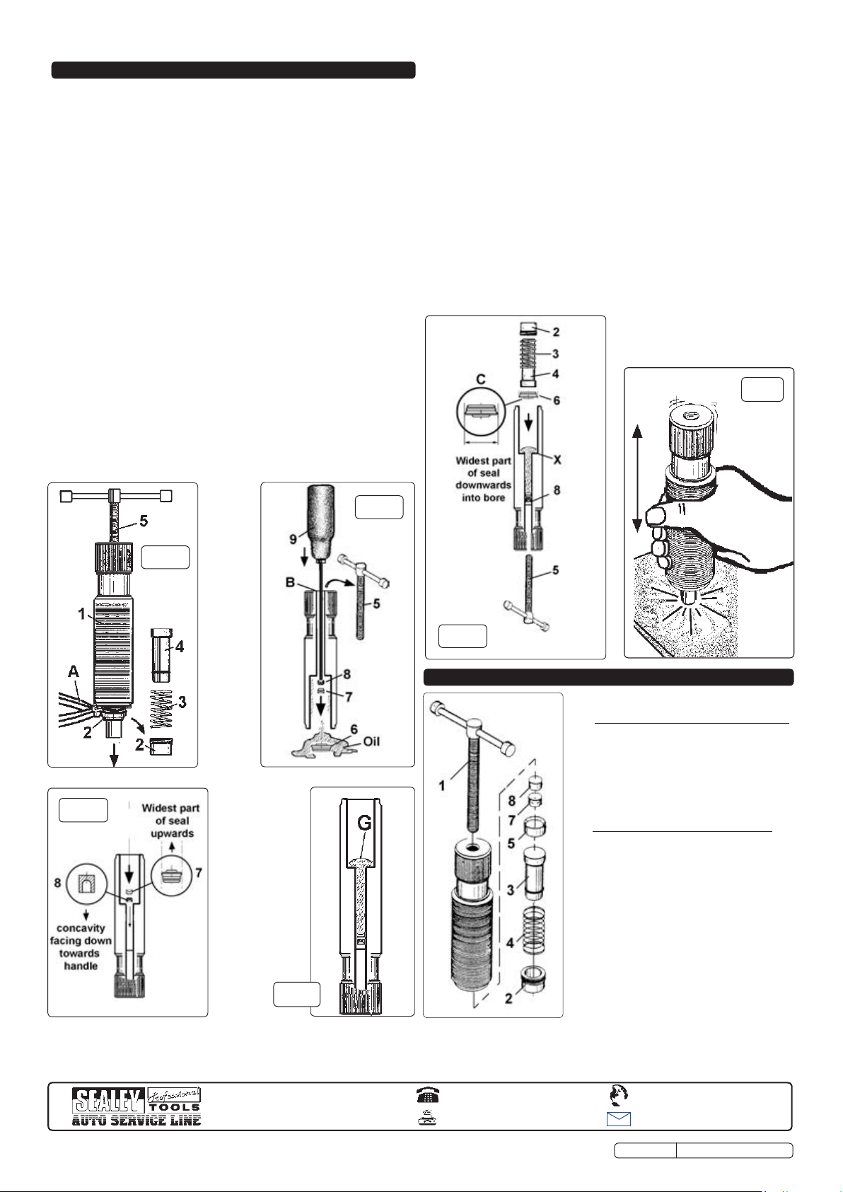
5.2.1. Dismantle by removing the ram cover (fig.3.2) with soft jaw grips
(fig.3.A) (body may have to be held in a soft jaw vice, ensure
body thread is not damaged). Caution! The cover is spring
loaded, take care when removing. Carefully remove
components 2, 3, and 4 from the cylinder.
5.2.2. Screw T-handle (fig.4.5) down as far as it will go, then unscrew
and remove it from the body (fig.4.5).
5.2.3. Push a narrow screw driver (fig.4.9), or a rod of appropriate
diameter, down the small opening in head of ram (B), in order to
push components 6, 7, and 8, plus the oil, out of the main
cylinder. Note: A medium force may be required.
5.2.4. Remove remaining oil from main cylinder, clean all components
and replace any showing signs of damage or wear.
5.2.5. Take small seal and piston (fig.5.7 & 8) and gently push them
down the narrow bore of the cylinder ensuring the metal piston
(8) is first, with the concave face pointing in the direction of the
T-handle, and the seal (fig.5.7) second, with the widest part of
the seal facing upwards towards the main cylinder (fig.5). Push
into bore as far as possible.
5.2.6. Pour 15grms of oil into the bore (fig.6). Insert larger seal (fig.7.6)
as shown, with the widest part of the seal facing downwards into
the bore. Push down into main cylinder as far as ‘X’ (fig.7)
followed by piston (fig.7.4) and spring (fig.7.3).
5.2.7. Refit (do not overtighten) ram cover (fig.7.2) and replace T-
handle (fig.7.5).
WARNING! The correct orientation of pistons and seals in
the ram is critical.
5.2.8. Screw T-handle into ram until it contacts small piston and
then turn a further two or three times.
5.2.9. Remove T-handle and firmly bounce the ram piston (fig.8) on a
hard, but non-damaging, surface 6 to 10 times to consolidate the
oil. Replace the T-handle, wipe
clean and the ram is ready for
use.
fig.8
fig.5
fig.4
fig.3
fig.7
6. SERVICE PARTS & NOTES
6.1 MAINTENANCE OF EARLY MODELS.
Please note that earlier models of the
PS990 were filled with a hydraulic
grease.
WARNING! Do not put oil into units
previously filled with grease as the
seals will be configured for grease only
and will leak if used with oil.
6.2 CONVERTING OLD UNITS TO OIL
The old type grease filled PS990 can
be converted for use with oil by
replacing the internal components with
those supplied in the repair kit
shown on left Part No PS982/8002. Do
not mix old and new components. A
single 15grm refill of oil may be
obtained by quoting Part No.PS982/OIL
fig. 6
NOTE: It is our policy to continually improve products and as such we reserve the right to alter data, specifications and component parts without prior notice.
IMPORTANT: No liability is accepted for incorrect use of this product.
WARRANTY: Guarantee is 12 months from purchase date, proof of which will be required for any claim.
INFORMATION: For a copy of our catalogue and latest promotions call us on 01284 757525 and leave your full name, address and postcode.
Sole UK Distributor
Sealey Group,
Bury St. Edmunds, Suffolk.
01284 757500
01284 703534
www.sealey.co.uk
Web
sales@sealey.co.uk
email
PS981.V2 ISSUE No:1 05/01/09
 Loading...