

Page 1
INSTRUCTIONS FOR
IMPORTANT: PLEASE READ THESE INSTRUCTIONS CAREFULLY. NOTE THE SAFE OPERATIONAL REQUIREMENTS, WARNINGS & CAUTIONS. USE
THE PRODUCT CORRECTLY AND WITH CARE FOR THE PURPOSE FOR WHICH IT IS INTENDED. FAILURE TO DO SO MAY CAUSE DAMAGE AND/OR
PERSONAL INJURY AND WILL INVALIDATE THE WARRANTY. KEEP THESE INSTRUCTIONS SAFE FOR FUTURE USE.
POWER SCAN AUTOMOTIVE PROBE/SCOPE
0-30V
MODEL NO: PP100.V2
Thank you for purchasing a Sealey product. Manufactured to a high standard, this product will, if used according to these instructions,
and properly maintained, give you years of trouble free performance.
Refer to
instruction
manual
Wear eye
protection
1. SAFETY
IF YOU ARE IN ANY DOUBT ABOUT ELECTRICAL SAFETY CONSULT A QUALIFIED ELECTRICIAN.
9 Only for use with 2V - 24V DC systems.
8 DO NOT apply voltage or current to the probe that exceeds the specified maximum of 30V DC.
8 DO NOT use on any circuit directly or indirectly connected to AC lines or any other AC power source.
8 DO NOT use with any component or circuits on the vehicle’s ignition system.
9 Before using this device, check the vehicle’s electrical wiring and disconnect any part or system sensitive to voltage and current pulses
such as air bags, electronic control modules, etc.
9 Always check the instructions and procedures indicated in the vehicle service manual before attempting to disconnect any part or
sub-system of the electrical circuit.
9 When not in use, store carefully in a safe, dry, childproof location. Avoid extremes of temperature.
8 DO NOT use the tool around explosive gases, vapour or dust. When the power switch is operated (forwards or backwards), voltage is
present at the tip of the probe which may cause sparks when contacting ground or certain other circuits.
8 DO NOT use leads if damaged or if the wire is bared in any way.
8 DO NOT use the equipment when you are tired or under the influence of alcohol, drugs or intoxicating medicines.
8 DO NOT use this tool for any purpose other than that for which it has been designed.
2. INTRODUCTION
Probably the most advanced automotive probe on the market, with a huge range of functions for effective automotive diagnostics, making short
circuits and bad earths easy to nd. Features a scope function to visually test component signals, with the added benet of maximum/minimum
volts, frequency and duty cycle displayed. Allows components to be activated in situ or prior to installation. The y lead allows continuity and polarity
testing with a high-contrast colour LCD display giving a 7mm high read-out. Features audible and positive/negative voltage indicator and two
integral work lights. 6mtr lead connects to the battery supply and reaches all areas of the vehicle. Includes a vehicle accessory socket adaptor and
6mtr extension cable. Supplied in carry-case.
3. SPECIFICATION
Model no: ............................................................... PP100.V2
DC voltage: .................................................................. 0-30V
Frequency: ............................................................... 0-10KHz
Duty cycle: ...................................................................1-99%
Resistance: ..........................................................50Ω-199kΩ
Continuity test audible: .................................................. <50Ω
Scope function: ................................................................ yes
Back light: ........................................................................ yes
Circuit breaker reset: ........................................................ yes
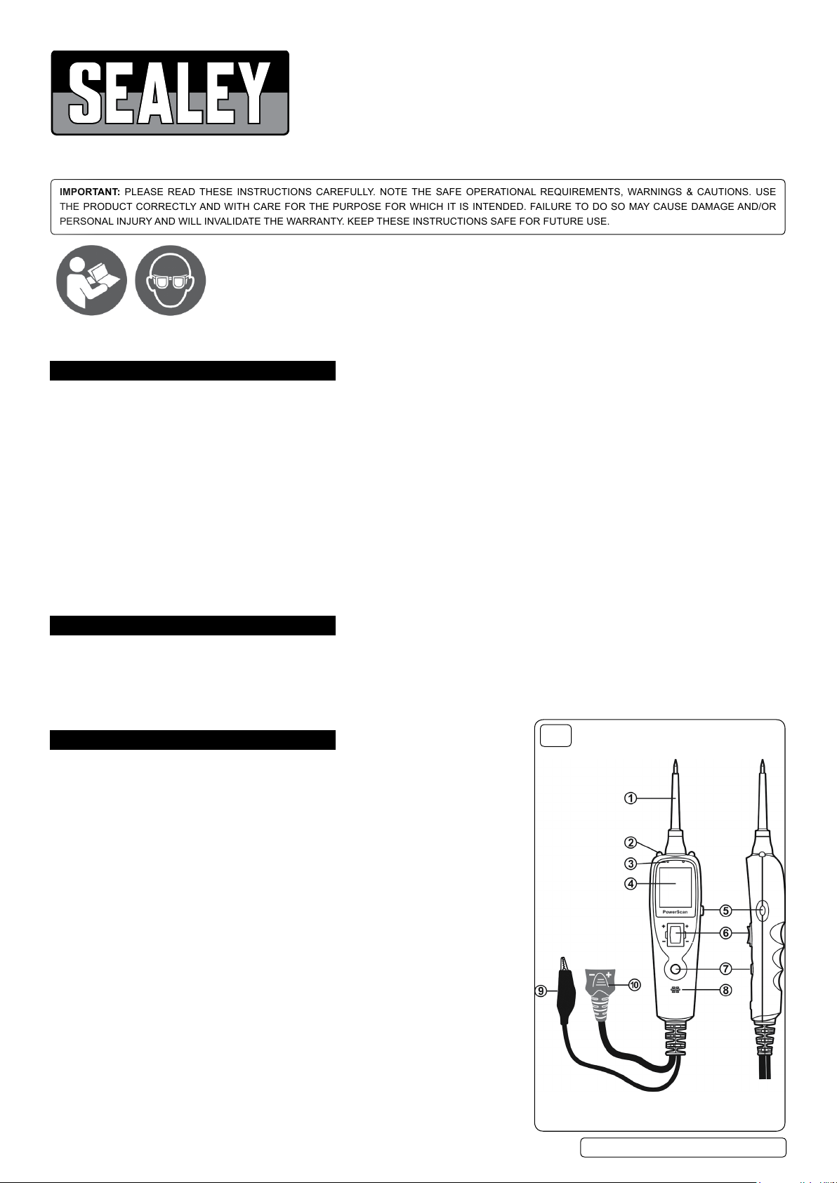
g.1
Key to fig.1
1 Probe Tip – Contacts the circuit or component to be tested.
2 Work Lights – Illuminate work area.
3 Red/Green Polarity Indicator – Identifies positive, negative or open circuits.
The red indicator lights when the probe tip is contacting a positive circuit.
The green indicator lights when the probe tip is contacting a negative circuit.
4 LCD Display
5 Circuit Breaker Reset – Resets the tool when the circuit breaker is tripped
6 Power Switch – When operated conducts a positive or negative battery current
to the tip for activating and testing the function of electrical components.
7 Mode Button – Selects the work mode: DC voltage, scope, resistance &
audible indicator.
8 Speaker – When the audible indicator is turned on, emits a tone.
9 Auxiliary Ground Lead
10 Adaptor – Connects to the battery supply via clips or cigarette lighter adaptor.
© Jack Sealey Limited
Original Language Version
PP100.V2| Issue 1 13/06/17
Page 2
4. OPERATION
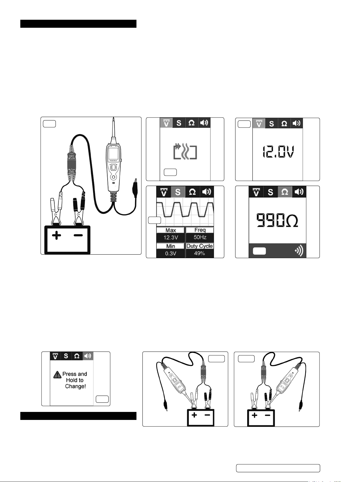
4.1. BasicConnections(g.2)
4.1.1. Unroll the probe cable. Connect the red battery clip to the POSITIVE terminal of the vehicle’s battery. Connect the black battery clip to
the NEGATIVE terminal of the vehicle’s battery.
4.1.2. Alternatively use the 12V vehicle accessory socket adaptor instead of battery clips.
4.1.3. When the probe is rst connected to the battery, the probe will go into voltage mode.
4.1.4. The audible indicator will be heard and the two LED work lights will switch on to illuminate the test area of the probe.
4.2. Quick Self Test
4.2.1. Press the power switch forward to activate the probe with a positive voltage. The positive LED should light red and the LCD
screen will display the battery (supply) voltage. If the audible indicator feature is turned on, a high-pitched tone will emit. Release the
power switch, the LED will turn off and the audible indicator will cease.
4.2.2. Press the power switch rearward to activate the probe with a negative voltage. The negative LED should light green and the LCD
screen will display ‘0.0V’. If the audible indicator feature is turned on, a low-pitched tone will emit. Release the power switch, the LED
will turn off and the audible indicator will cease. The probe is now ready to use.
4.2.3. If the tool failed to operate, depress the circuit breaker reset button on the right hand side of the housing and repeat the test.
g.2
g.4
g.3
g.5
g.6
4.3. Circuit Breaker
4.3.1. The tool is short circuit protected. The internal circuit breaker will trip in case of overload. The maximum current rating is 8Amps.
4.3.2. When the circuit breaker is tripped, the LCD will display as (g.3). All the other functions of the tool will remain active. When the circuit
breaker is tripped, the tool will NOT be able to energise the probe tip when the power switch is pressed. Intentionally tripping the
breaker and using the tool to probe can be considered a safeguard against unintentionally pressing the power switch.
4.4. Operating Modes
4.4.1. Voltage - With the tool in this mode when contacting the probe tip to a live circuit, the LCD screen will display the voltage of the circuit
to the nearest 0.1Volt (g.4).
4.4.2. Scope - With the tool in this mode contacting the probe tip to a live circuit, the LCD display will read the maximum voltage,
minimum voltage, frequency and duty cycle (g.5). There are 22 settings in scope mode. The display automatically changes the ‘Y’
axis scale to give clearer readings.
4.4.3. Resistance - With the tool in this mode, contacting the probe tip to a component, the LCD display will show the resistance between
the probe tip and the auxiliary ground lead (g.6).
4.4.4. Audible Indicator On/Off - With the tool in this mode, press and hold the mode button to change the function of the audible indicator
(g.7).
g.8a g.8b
g.7
5. TESTING PROCEDURES
5.1. Voltage and Polarity Test
5.1.1. With the tool set in voltage mode, when the probe tip contacts a POSITIVE circuit, the red LED will light and the LCD screen will
display the voltage to the nearest 0.1V. If the audible indicator is activated, a high pitched tone will emit (g.8a).
5.1.2. When the probe tip contacts a NEGATIVE circuit, the green LED will light and the LCD screen will display the voltage to the nearest
0.1V. If the audible indicator is activated, a low pitched tone will emit (g.8b).
If the probe tip contacts an OPEN circuit, neither LED will function.
© Jack Sealey Limited
Original Language Version
PP100.V2| Issue 1 13/06/17
Page 3
5.2. Continuity Testing
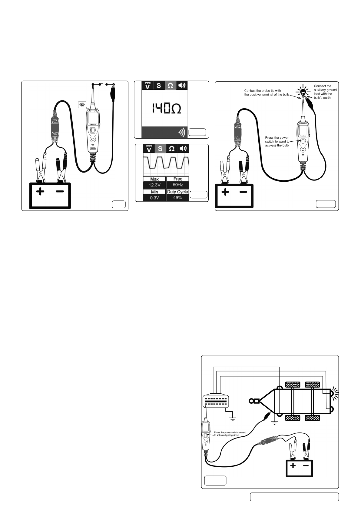
5.2.1. While the probe is in resistance mode, continuity can be tested on wires and components attached to or disconnected from the
vehicle’s electrical system by utilizing the probe tip when connected with a chassis earth or the auxiliary earth lead (g.9).
5.2.2. Where continuity is present the LCD screen will display ‘0.0Ω’ and the green LED will illuminate. If the audible indicator is turned on a
low pitched tone will emit.
5.2.3. In any other instance the LCD screen will display the resistance value (g.10). For any resistance value greater than 199kΩ the LCD
screen will display ‘OL’.
5.2.4. Another method to check for continuity of connections to earth or the battery is to use the power switch. If the circuit breaker trips,
there is a good, low-resistance connection.
g.10
g.11
g.9
g.12
5.3. Signal Circuit Testing
5.3.1. The tool can be used as a trouble shooting aid to test sensors/components in a circuit where a DTC (Diagnostic Trouble Code) has
been detected during an on-board diagnostic scan.
5.3.2. Always refer to the vehicle manufacturer’s service instructions, or a proprietary manual to establish the current procedure and data for
testing and location of the sensor/component to be tested.
5.3.3. Set the tool to scope mode and attach the auxiliary ground lead to earth. Use the probe tip on the terminals of the sensor/component
as described in the manufacturer’s test procedures and observe the signal and readings on the LCD display screen (g.11).
5.3.4. Any abnormal signals or readings may indicate a fault with the sensor/component.
5.4. Activating Components Removed From Vehicle Electrical System (Such as fuel pumps, starter solenoids, magnetic clutches,
blowermotors,coolingfans,lightsetc.)
5.4.1. By using the probe tip together with the auxiliary earth lead, components can be activated, thereby testing their function.
5.4.2. Set the tool to the voltage mode.
5.4.3. Connect the auxiliary earth lead clip to the negative terminal of the component to be tested. Contact the probe to the positive terminal
of the component. The test indicator should illuminate green, indicating continuity through the component (g.12).
5.4.4. Quickly press the power switch forward to the positive position and release. If the test indicator changes from green to red, you may
proceed with further activation. Press and hold the power switch forward to energise the component being tested.
5.4.5. If circuit breaker activates, the unit has been overloaded. The maximum current rating is 8Amps. This could happen for the following
reasons:
a) Where the tip of the tester has made contact is a direct earth or a negative voltage.
b) The component has a short circuit.
c) The component requires a high current (e.g. a starter motor).
Note: The tool is equipped with a built in circuit breaker for overload protection. Should the circuit breaker be activated, reset using the
circuit breaker reset (g.1 item 5).
5.5. Testing Trailer Lights and Connections
5.5.1. Set the tool to the voltage mode.
5.5.2. Connect to a battery of the correct voltage for the trailer electrical
system (g.13).
5.5.3. Clip the auxiliary earth lead to an earth on the trailer chassis.
5.5.4. Probe the contacts of the trailer’s electrical connection socket
whilst pressing the power switch forward to the positive position.
5.5.5. This will allow you to check the function and orientation of the
trailer lighting system.
© Jack Sealey Limited
Original Language Version
g.13
PP100.V2| Issue 1 13/06/17
Page 4
5.6. Activating Components With a Positive(+)Voltage Within Vehicle Electrical System
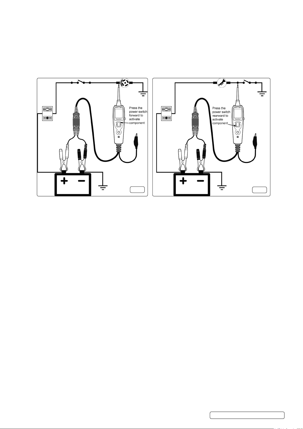
5.6.1. Set up the tool as shown in g.14 and set to voltage mode.
5.6.2. Contact the probe tip to the positive terminal of the component, the test indicator should illuminate green. Whilst observing the test
indicator, quickly press and release the power switch forward to the positive position. If the indicator changes instantly from green to
red the tool is ready for use.
5.6.3. If the circuit breaker activates, the unit has been overloaded. This could happen for the following reasons:
a) The tip’s contact went to direct earth.
b) The component has a short circuit.
c) The component is a high current component (i.e. starter motor)
WARNING! Randomly applying voltage to certain circuits can cause damage to a vehicle’s electronic components. It is
strongly advised to use the correct circuit diagram and diagnostic procedures whilst performing this test.
g.14
5.7. Activatingcomponentswithanegative(-)voltagewithinvehicleelectricalsystem
5.7.1. Set up the tool as shown in g.15 and set to voltage mode.
5.7.2. Contact the probe tip to the negative terminal of the component, the test indicator should illuminate red.
5.7.3. Whilst observing the test indicator, quickly press the power switch rearwards to the negative position and release it. If the indicator
changes instantly from red to green the tool is ready for use.
5.7.4. If the circuit breaker activates, the unit has been overloaded. This could happen for the following reasons:
a) Where the tip of the tester has contacted is a direct positive voltage.
b) The component has a short circuit.
c) The component is a high current component (e.g. a starter motor) (8Ampmax.)
WARNING! With this function a vehicle’s fuses may blow when the probe tip is earthed in series with them.
5.8. Checking For Bad Earth Contacts
5.8.1. With the tool connected to the battery supply, set to the voltage mode.
5.8.2. Probe the suspected earth wire or contact with the probe tip. Observe the colour of the test indicator.
5.8.3. Press the power switch forward to the positive position and release it. If the test indicator changes from green to red, this is not a true
earth. If the circuit breaker tripped when the power switch was pressed forward, this circuit is more than likely a direct earth. Note that
high current components such as a starter motor will also cause the test indicator to trip off during this check.
5.9. Following and Locating Short Circuits
5.9.1. In most cases a short circuit will appear by a fuse or a fusible link blowing or an electrical protection device tripping (i.e. a circuit
breaker).
5.9.2. Connect the tool to the battery supply. Remove the blown fuse from the fuse box. Use the probe to activate and energise each of the
fuse contacts. The contact which trips the probe circuit breaker is the shorted circuit. Take note of this wire’s identication code or
colour.
5.9.3. Follow the wire as far as you can along the wiring harness. For instance if you are following a short in the brake light circuit you may
know that the wire must pass through the wiring harness at the door sill. Locate the colour-coded wire in the harness and expose it.
5.9.4. Probe through the insulation with the probe tip depress the power switch forward to activate and energise the wire. If the circuit
breaker tripped you have veried the shorted wire.
5.9.5. Cut the wire and energise each end with the probe. The wire end which trips the circuit breaker again is the shorted circuit and it
will lead you to the shorted area. Follow the wire in the shorted direction and repeat this process until the short is located.
5.10. Voltage Differentials
5.10.1. The red/green LED’s will only illuminate when the voltage at the probe tip is within ±0.8Volts of the supply battery voltage. This is a
useful feature for some fault nding procedures.
5.10.2. If the circuit voltage is not within ±0.8Volts of the supply battery voltage, the LCD screen will display the voltage gure at the circuit but
no LED’s will illuminate. This will indicate a difference of ±0.8Volts between the supply battery voltage and the voltage in the circuit
being tested. Remove the probe tip from the circuit and press the power switch forward. The LCD screen will now display the
-supply battery voltage. The difference between the supply battery voltage and the circuit voltage can now be determined.
5.11. Using With Sensitive Circuits
5.11.1. The LED’s and the LCD screen draw no more than 1mA current ensuring that the tool is safe for use as a multimeter or test light on
sensitive ECU controlled electronic circuits such as the airbag circuit.
g.15
© Jack Sealey Limited
Original Language Version
PP100.V2| Issue 1 13/06/17
Page 5
5.11.2. Before attempting to use the tool on any sensitive circuit, it is recommended that the auxiliary earth lead is connected to the probe tip
and the power switch pressed forward to trip the circuit breaker. This will prevent the probe tip from being inadvertently
use and causing damage to electronic components.
5.11.3. After use, press the reset button to restore normal power switch function.
activated during
6. MAINTENANCE
6.1. Power Switch
6.1.1. Although designed to be a no maintenance tool, the power switch may deteriorate over a period of time through fair wear and tear.
6.1.2. Replacement power switches are available through your Sealey stockist and are simple to replace.
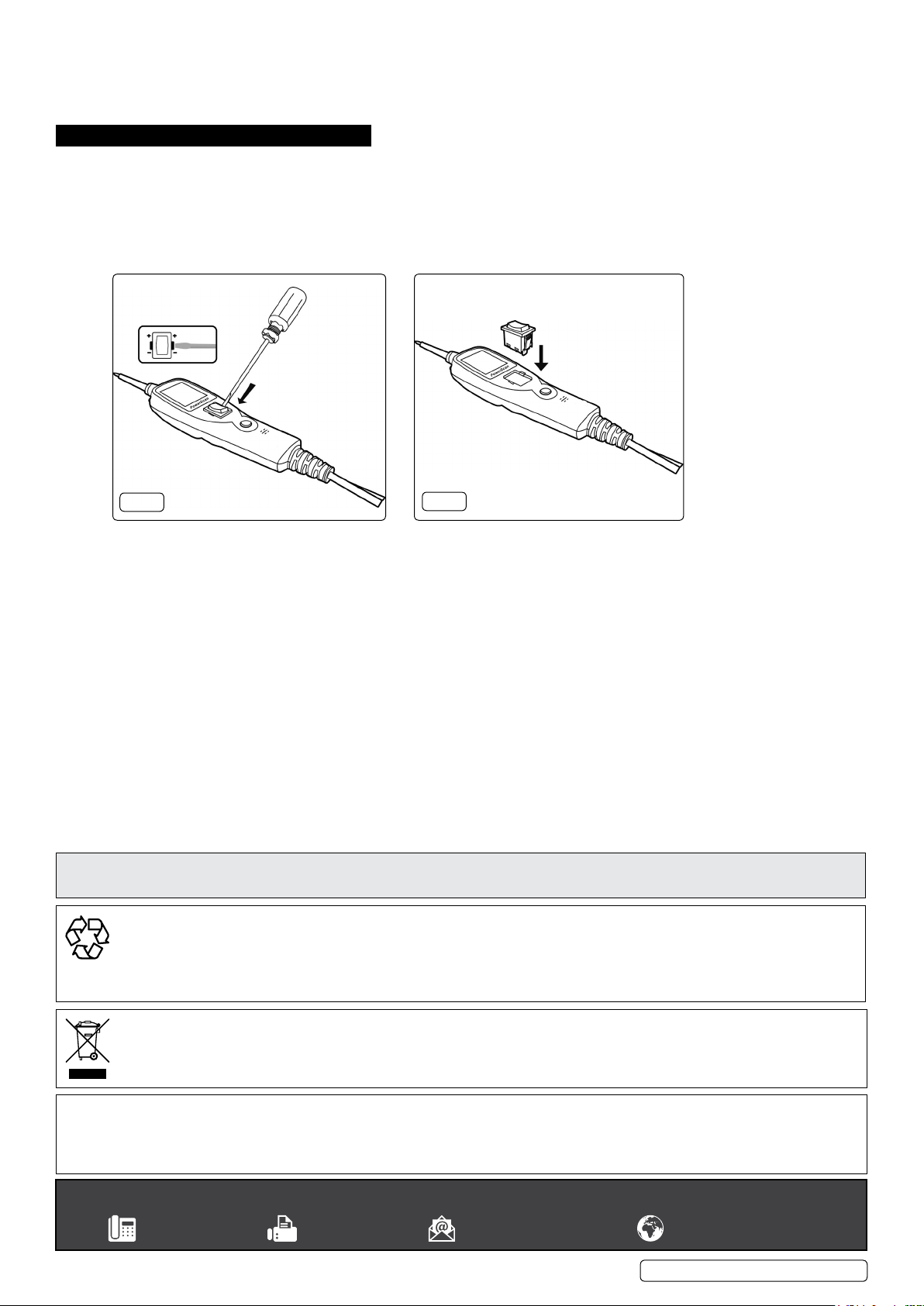
6.2. Power Switch Replacement
6.2.1. Carefully prise the worn power switch from the main casing (fig.16).
6.2.2. Install the replacement power switch by carefully pressing it squarely into the main casing until it locks into place (fig.17).
6.2.3. Connect the tool to a power supply and test the power switch for functionality.
g.16
Parts support is available for this product. To obtain a parts listing and/or diagram, please log on to
www.sealey.co.uk, email [email protected] or telephone 01284 757500
ENVIRONMENT PROTECTION
Recycle unwanted materials instead of disposing of them as waste. All tools, accessories and packaging should be sorted, taken to
a recycling centre and disposed of in a manner which is compatible with the environment. When the product becomes completely
unserviceable and requires disposal, drain any fluids (if applicable) into approved containers and dispose of the product and fluids
according to local regulations.
g.17
WEEE REGULATIONS
Dispose of this product at the end of its working life in compliance with the EU Directive on Waste Electrical and Electronic Equipment
(WEEE). When the product is no longer required, it must be disposed of in an environmentally protective way. Contact your local solid
waste authority for recycling information.
Note: It is our policy to continually improve products and as such we reserve the right to alter data, specifications and component parts without prior
notice.
Important: No Liability is accepted for incorrect use of this product.
Warranty: Guarantee is 12 months from purchase date, proof of which is required for any claim.
Sealey Group, Kempson Way, Suffolk Business Park, Bury St Edmunds, Suffolk. IP32 7AR
© Jack Sealey Limited
Original Language Version
PP100.V2| Issue 1 13/06/17
 Loading...