

Sealey Power PRODUCTS TP96.V2,Power PRODUCTS TP9624.V2 Instructions Manual
INSTRUCTIONS FOR:
DIESEL/FLUID TRANSFER PUMP
MODEL No's: TP96.V2 & TP9624.V2
Thank you for purchasing a Sealey product. Manufactured to a high standard this product will, if used according to these instructions
and properly maintained, give you years of trouble free performance.
IMPORTANT: PLEASE READ THESE INSTRUCTIONS CAREFULLY. NOTE THE SAFE OPERATIONAL REQUIREMENTS, WARNINGS AND
CAUTIONS. USE THIS PRODUCT CORRECTLY AND ONLY FOR ITS INTENDED PURPOSE. FAILURE TO DO SO MAY CAUSE DAMAGE
OR PERSONAL INJURY, AND WILL INVALIDATE THE WARRANTY. RETAIN THESE INSTRUCTIONS FOR FUTURE USE.
1. SAFETY INSTRUCTIONS
Maintain the pump in good condition (use an authorised service agent).
Replace or repair damaged parts. Use recommended parts only. Non
authorised parts may be dangerous and will invalidate the warranty.
Keep the pump clean for best and safest performance.
Ensure the power supply (vehicle battery) corresponds with the requirements
of the pump. TP96.V2 12Volt, TP9624.V2 24Volt DC power supply.
Ensure that there is more liquid in the suction tank than will be pumped.
Ensure that the capacity of the receiving tank is sufficient to hold the pumped
fuel.
Wear safety goggles and gloves, and protective clothing when working
around fuel. A full range of personal safety equipment is available from your
local Sealey dealer.
Use the pump in an appropriate working area for its function.
Keep area clean and tidy and free from unrelated materials, and ensure there
is adequate lighting.
Maintain correct balance and footing. Ensure the floor is not slippery and
wear non slip shoes.
Keep children and unauthorised persons away from the working area.
DO NOT ‘dry run’ the pump without fuel. This will damage the pump’s internal
components and will invalidate your warranty.
DO NOT operate the pump continuously for more than 30 minutes. The duty
cycle of the unit is 30 minutes, after which the motor must be left to cool
down.
DO NOT run the unit for more than 2-3 minutes with the delivery nozzle
closed.
DO NOT start or stop the pump by connecting or disconnecting the battery
clamps.
DO NOT operate the pump with wet hands.
DO NOT use the pump where explosive or flammable vapours may be
present.
DO NOT tamper with the pump connections.
WARNING! DO NOT use the unit to pump the following fluids: Petrol,
inflammable liquids with PM <55°C, water, alimentary liquids with
viscosity >20 cSt., corrosive chemicals and solvents.
g.1
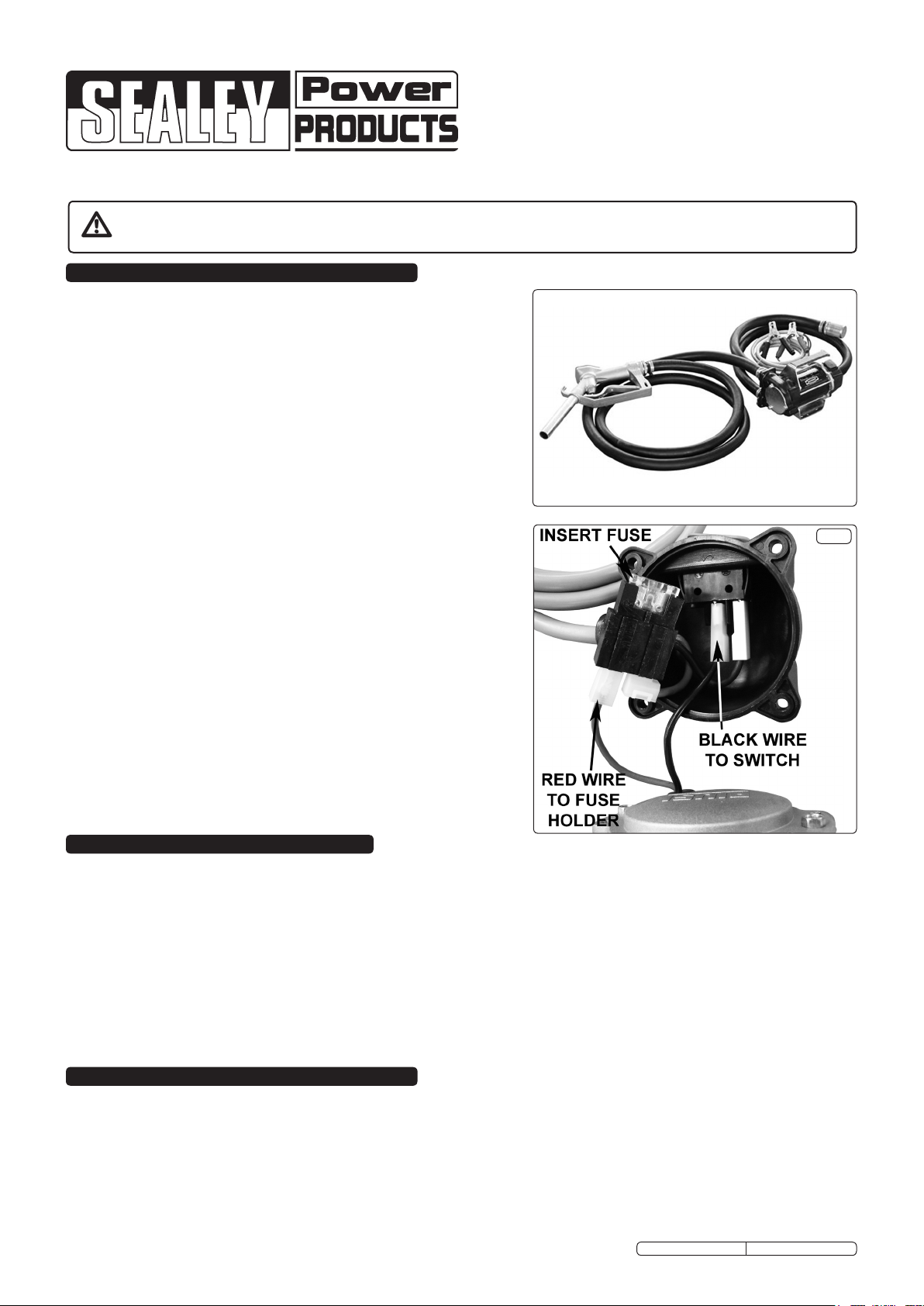
2. INTRODUCTION
Electric 12 or 24V pump with battery clips. Suitable for lling diesel vehicles in the eld. Self-priming unit delivers up to 43ltr a minute of uid
for TP96 and 46ltr a minute of uid for TP9624. Supplied with 4mtr of hose and TP108 Manual Delivery Nozzle. Includes on/off switch, carry
handle, mounting plate and suction hose lter.
Model TP96.V2
Voltage . . . . . . . 12V
Speed ........ 2600rpm
Current . . . . . . . 22A
Power ........260W
Fuse . . . . . . . . . 25A
Duty cycle.....30min/hr
Flow Rate .....43ltr/min
Model TP9624.V2
Voltage . . . . . . . 24V
Speed ........ 2600rpm
Current . . . . . . . 13A
Power ........160W
Fuse . . . . . . . . . 15A
Duty cycle.....30min/hr
Flow Rate .....46ltr/min
3. ASSEMBLY
WARNING! Use the pump fittings provided for connecting the suction and delivery tubes to the inlet and outlet ports of the pump.
3.1 Before using the pump, unpack all materials and inspect the pump unit for damage.
3.2 Connect the wires from the pump motor (fig.2-1) to the switch housing (fig.2-2) as shown in fig.1 and insert the fuse into the fuse holder.
Attach the switch housing (fig.2-2) to the pump motor (fig.2-1) using the four screws provided. Ensure that the 'O' ring seal is fitted
between the switch housing and the pump motor.
3.3 A mounting bracket is supplied (fig.2-4) which can be attached to the lower end of the inlet/outlet casting (fig.2-5) using the socket cap
screws provided. The pump can be mounted in either a horizontal or a vertical axis, refer to fig.3. Ensure that the pump is mounted so
that the on/off switch is visible and readily accessible.
Original Language Version
TP96.V2, TP9624.V2 Issue No: 1 - 30/04/12
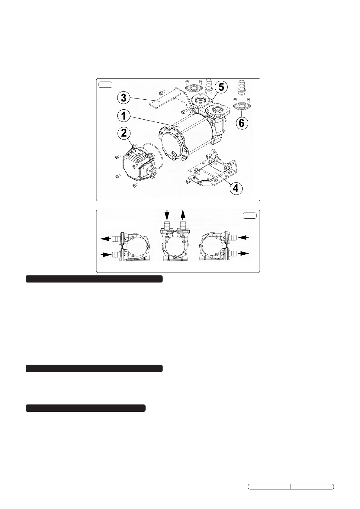
3.4 Attach the handle (fig.2-3) to the upper part of the inlet/outlet casting (fig.2-5) using a single socket cap screw.
3.5 Attach the pipe fittings (fig.2-6) to the inlet/outlet casting (fig.2-5) using the screws provided.
3.6 The hose is supplied in a single length and should be cut in two to make the suction and delivery hoses. Review your installation site to
decide on the lengths required and cut the hose accordingly.
3.7 Push the filter attachment into one end of the suction hose and secure it with one of the hose clips supplied. Identify the inlet port by
means of the flow arrow on the top of the inlet/outlet casting and then attach the hose to the inlet port. Secure with a hose clip.
3.8 Insert the delivery nozzle provided into one end of the delivery hose and secure it with a hose clip. Attach the delivery hose to the outlet
port on the pump body and secure with a hose clip.
g.2
g.3
4. OPERATION
WARNING! Check to ensure you are connecting your pump to the correct voltage power supply for model.
4.1 Before each use, clean the inlet and outlet ports. Remove any dust or packing material that may have collected during transport or
between uses.
4.2 Lower the suction tube (with filter attached) into the fuel storage tank.
4.3 Place the delivery nozzle in the fuel tank of the vehicle.
4.4 Attach the red battery clamp to the positive (+) terminal of the vehicle’s battery, and the black clamp to the negative (-) terminal.
4.5 Before turning the pump on, ensure that the delivery nozzle is in the ‘OFF’ position.
4.6 Turn the switch ‘ON’. The pump is capable of operating with the delivery nozzle closed for 2-3 minutes maximum.
4.7 Grip the nozzle firmly and squeeze the trigger to begin transferring fuel.
4.8 Release the trigger to stop the fuel flow when the transfer is complete.
4.9 Turn the pump switch ‘OFF’.
Note: The fuel pump may switch off automatically if there is insufficient voltage or a fault in the electrical connection. If this happens,
release the trigger handle, keeping the nozzle in place, and turn the pump switch off. Investigate the cause of the interruption.
5. MAINTENANCE
5.1 Check the pump casing, suction and delivery tubes regularly for leaks.
5.2 Keep the pump clean for easy detection of leaks.
5.3 Remove and clean the filter every 10 hours of operation or sooner if the transfer flow begins to decrease.
5.4 Dispose of environmentally hazardous parts in the proper manner.
6. PERFORMANCE DATA
6.1 The graph in fig.4 refers to the following operating conditions:
Fluid: Diesel
Temperature: 20°C
Suction Conditions: The suction pipe and the pump are in such a position relative to the fluid level that a pressure of 0.3bar is
generated at the nominal flow rate. Flow rate is shown as a function of back pressure.
6.2 Under different suction conditions higher pressure values can be created that reduce the flow rate compared to the same back pressure
values.
6.3 To obtain the best performance, it is important to reduce the loss of suction pressure as much as possible by keeping the suction
filter clean and ensuring that the suction hose is of the correct diameter and as short as possible.
Original Language Version
TP96.V2, TP9624.V2 Issue No: 1 - 30/04/12
 Loading...