

Page 1

INSTRUCTIONS FOR:
PLASMA CUTTER
MODEL No: PL120/1.V3
Thank you for purchasing a Sealey plasma cutter. Manufactured to a high standard this product will, if used according to these instructions and properly
maintained, give you years of trouble free performance.
IMPORTANT: BEFORE USING THIS PRODUCT, PLEASE READ THE INSTRUCTIONS CAREFULLY. MAKE CAREFUL NOTE OF SAFETY INSTRUCTIONS, WARNINGS
AND CAUTIONS. THIS PRODUCT SHOULD ONLY BE USED FOR ITS INTENDED PURPOSE. FAILURE TO DO SO MAY CAUSE DAMAGE AND/OR PERSONAL
INJURY AND WILL INVALIDATE THE WARRANTY. RETAIN THESE INSTRUCTIONS FOR FUTURE USE.
1. SAFETY INSTRUCTIONS
1.1. ELECTRICAL SAFETY
WARNING! It is the responsibility of the owner and the operator to read, understand and comply with the following:
You must check all electrical products, before use, to ensure that they are safe. You must inspect power cables, plugs, sockets and any other
connectors for wear or damage. You must ensure that the risk of electric shock is minimised by the installation of appropriate safety devices. A
Residual Current Circuit Breaker (RCCB) should be incorporated in the main distribution board. We also recommend that a Residual Current
Device (RCD) is used. It is particularly important to use an RCD with portable products that are plugged into a supply which is not protected
by an RCCB. If in any doubt consult a qualified electrician. You may obtain a Residual Current Device by contacting your Sealey dealer.
You must also read and understand the following instructions concerning electrical safety.
1.1.1. The Electricity at Work Act 1989 requires that all portable electrical appliances, if used on business premises, are tested by a
qualified electrician, using a Portable Appliance Tester (PAT), at least once a year.
1.1.2. The Health & Safety at Work Act 1974 makes owners of electrical appliances responsible for the safe condition of those appliances
and the safety of the appliance operators. If in any doubt about electrical safety, contact a qualified electrician.
1.1.3. Ensure that the insulation on all cables and on the appliance is safe before connecting it to the power supply. See 1.1.1. and 1.1.2.
and use a Portable Appliance Tester.
1.1.4. Ensure that cables are always protected against short circuit and overload.
1.1.5. Regularly inspect power supply cables and plugs for wear or damage and check all connections to ensure that none is loose.
1.1.6. Important: Ensure that the voltage marked on the appliance matches the power supply to be used and that the supply is protected by
a suitably rated fuse or breaker (see right).
1.1.7. DO NOT pull or carry the appliance by the power cable.
1.1.8. DO NOT pull the plug from the socket by the cable.
1.1.9. DO NOT use worn or damaged cables, plugs or connectors. Immediately have any faulty item
repaired or replaced by a qualified electrician.
1.1.10. DO NOT use this product with a cable extension reel.
1.1.11. This product requires a 3-PHASE supply, so no plug is fitted. You must contact a qualified
electrician to ensure that a suitable supply is available. We recommend you discuss the
installation of a industrial round pin plug and socket with your electrician.
WARNING! Reminder, the electrical installation of the plasma cutting unit must only be carried out by a qualified electrician.
Make sure that power supply cable is correctly connected to earth.
WARNING! Be very cautious if using a generator to power the plasma cutter. The generator must be self regulating and
stable with regard to voltage, waveform and frequency. The output must be greater than the power consumption of the
plasma cutter. If any of these requirements is not met the electronics within the plasma cutter may be affected.
NOTE:The use of an unregulated generator may be dangerous and will invalidate the warranty on the plasma cutter.
WARNING! The plasma cutter may produce voltage surges in the mains supply which can damage other sensitive equipment
(e.g. computers). To avoid this happening it is recommended that the plasma cutter is connected to a power supply that
does not feed any sensitive equipment.
3-PHASE SUPPLY
415V 10A FUSED
(OR 230V 16A FUSED)
MAXIMUM OUTPUT
WILL BE ACHIEVED ON
415V SUPPLY
1.2. GENERAL SAFETY
DANGER! Direct contact with the plasma cutter circuit or torch is dangerous. You MUST unplug the plasma cutter from the mains power
supply, (and the compressed air supply) before connecting or disconnecting cables or performing maintenance or service.
Keep the plasma cutter, cables and torch in good condition. (Take immediate action to repair or replace damaged parts).
Use recommended parts and accessories only. (Unapproved parts may be dangerous and will invalidate the warranty).
Only use the cutting torch provided with the system and ensure that any replacement is of the same type.
Use the plasma cutter in a suitable work area. Ensure that the area has adequate ventilation as welding/cutting fumes are harmful. For
enclosed areas we recommend the use of an extraction system. If you are not able to provide adequate extraction and/or ventilation, wear
a respirator suitable for protection against toxic fumes, smoke and gases.
Ensure that there are no obstructions to the flow of clean cool air and that there are no conductive dusts, corrosive vapours or humidity
which could enter the unit and cause serious damage.
WARNING: Use a welding head shield to protect your eyes and avoid exposing skin to the ultraviolet rays given off by the electric arc.
Always wear protective clothing, insulating gloves and shoes. Keep all protective items clean and undamaged.
Remove ill-fitting clothing before wearing protective clothing. Remove ties, watches, rings and other loose jewellery and contain long hair.
Stand correctly keeping a good footing and balance and ensure that the floor is not slippery. Wear non-slip shoes.
Ensure that the workpiece is correctly secured before operating the plasma cutter.
Avoid unintentional contact with workpiece. Accidental or uncontrolled switching on of the torch may be dangerous and will wear the nozzle.
Keep unauthorised persons away from the work area. Any persons working within the area must wear the same protective items as the
cutter operator.
DO NOT use cables and torch if the insulation is worn or connections are loose.
DO NOT attempt to fit any unauthorised torches, components or parts to the plasma cutting unit.
DO NOT cut surfaces that are painted, galvanic coated, oily or greasy.
DO NOT use cables over 10m in length.
DO NOT use any metallic structure which is not part of the workpiece to substitute the return cable of the plasma current.
DANGER! DO NOT cut near inflammable materials - solids, liquids or gases. Remove all flammable materials such as waste rags etc.
DO NOT cut containers or pipes which have held flammable materials - gases, liquids or solids. DO NOT cut materials that have been
cleaned with chlorinated solvents (or cut near such solvents) as the arc action may produce toxic gases.
Original Language Version
PL120/1.V3 Issue: 2 - 09/03/10
Page 2
DO NOT operate the plasma cutter while under the influence of drugs, alcohol or intoxicating medication, or if tired.
DO NOT use the plasma cutter for a task it is not designed to perform.
DO NOT operate the plasma cutter if any parts are damaged or missing as this may cause failure and/or personal injury.
DO NOT carry, or pull cutter by leads or cables. DO NOT strain or bend cables. DO NOT stand on cables or leads. Protect from heat and
sharp or abrasive items. Long lengths of slack must be gathered and neatly coiled. DO NOT place cables where they endanger others.
DO NOT get the plasma cutter wet or use in damp or wet locations or areas where there is condensation.
DO NOT touch the workpiece close to the cut as it will be very hot. Allow to cool. The cut edge of the workpiece may also be very sharp.
DO NOT touch the torch immediately after use. Allow the torch to cool.
When not in use store the unit in a safe, dry, childproof area.
1.3. AIR SUPPLY GENERAL SAFETY
WARNING! Turn off air supply and de-pressurise the system before connecting or disconnecting cables or performing maintenance or service.
WARNING! Ensure that correct air pressure is maintained and not exceeded. Recommended pressure 65-75psi, required air flow 120ltr/min.
WARNING! DO NOT exceed maximum pressure of 90psi. Excessive pressure may cause damage and/or personal injury.
Keep air hose away from heat, oil and sharp edges. Check air hose for wear before each use and ensure that all connections are secure.
DO NOT carry the cutter by the hose, or yank the hose from the air supply and DO NOT direct air from the air hose at yourself or others.
2. INTRODUCTION & SPECIFICATION
The PL120/1 Plasma Cutter produces a powerful cutting flame using only compressed air and electricity. Features pilot ignition for quick, clean
start-up. Cuts up to 12mm steel when on 415V 3-phase supply.
Mains voltage (50Hz) .....230V/415V-3ph
Absorbed power ...............12.4kVA
Absorbed current ...............31/18A
Cutting current Pos. 1 ......100% @ 30A
Cutting current Pos. 2 .......35% @ 50A
Max cutting depth (“C” class steel) ..12mm
Air pressure(max)................ 90psi
Air flow .....................120ltr/min
Weight .........................60kg
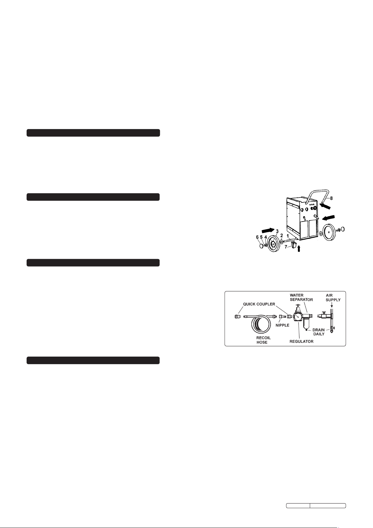
3. ASSEMBLY
Note: Numbers in brackets refer to item numbers in fig. 1.
3.1. Unpack the unit and slide the wheel axle (1) through the location holes at the front of the base.
3.2. Fit the 52mm washers (2) and the wheels (3).
3.3. Fit the 35mm washers (4), secure using the circlips provided (5) and fit the hub caps (6).
3.4. Fit the handle (8) and secure using the screws provided.
3.5. Raise the back of the unit and fit the rear support (7) using the four hex screws provided.
Note: The torch is supplied already connected to the power source by means of an internal connection.
No further assembly is required.
fig. 1
4. AIR SUPPLY
WARNING! Ensure that you read and understand the safety instructions in 1.3. before connecting the air supply.
4.1. An external compressed air supply must be attached to the plasma cutter. The supply must produce a working pressure of 65-75psi with
a capacity of 120ltr/min. The maximum entry pressure into the unit must not exceed 90psi.
4.2. To avoid excessive wear of the cutter ensure that the air supply is clean
and free from moisture. We recommend the fitting of a water separator/
filter unit as shown in fig. 2.
4.3. The air inlet filter system should be cleaned weekly.
4.4. Line pressure should be increased to compensate for unusually long air
hoses (over 8 metres). The minimum hose I.D. should be 10mm and
fittings must have the same bore.
4.5. Keep hose away from heat, oil and sharp edges. Check hoses for wear,
and make certain that all connections are secure.
Note: DO NOT use an oiler in the air system, the air must remain DRY at all times.
fig. 2
5. CONTROL INSTRUCTIONS
WARNING! Before operating the machine ensure that you read, understand and apply Section 1 safety instructions. Ensure that the
machine is disconnected from the power supply before moving or changing accessories.
5.1. Locating the machine
5.1.1. Ensure that the work area has a good airflow and that there is no dust, smoke or gas present.
5.1.2. Ensure that there is a minimum clearance of 500mm around the machine and there are no obstacles to prevent a cool air flow.
Also check to ensure that the ventilation grills are not blocked.
5.1.3. When moving the machine, disconnect the unit from the mains power supply and gather all cables safely.
5.2. Connecting the earth cable
Connect the work cable clamp to the workpiece or to the metallic workbench as follows:
5.2.1. Check that there is a good electrical contact. Caution: Ensure that you have made good contact on oxidised or insulated sheets.
5.2.2. Make the earth connection as close to the cutting area as possible.
5.2.3. DO NOT use metal structures or objects to make the earth contact (other than a metal workbench which is holding workpiece). To do so
may endanger the system safety and will give a poor cut. DO NOT make the earth connection to the part of the workpiece that will be removed.
5.3. ON/OFF switch
5.3.1. The on/off switch is located on the front panel of the machine (fig. 3.1). When the switch is in the “O” position the machine is turned off.
The machine is supplied set to operate on a 415V supply. To operate on a 230V supply, remove the change switch locking screw (fig. 3.2)
and refit in the hole on the left hand side of the change switch. When the switch is in either the 230V or the 415V position, the green light
(fig. 3.3) will illuminate. The control and duty circuits are now live but the torch will remain in ‘stand-by’ mode until the torch button is pressed.
5.4. Range selector
5.4.1. The cutting current is regulated by the switch on the front panel (fig. 3.4). This switch regulates the supply of current required in order to
cut different thicknesses of metal at different rates of progress.
Original Language Version
PL120/1.V3 Issue: 2 - 09/03/10
Page 3

5.5. Air regulator
5.5.1. Unlock the air regulator knob by pulling it away from the unit (fig. 3.5).
Turn the regulator knob until the pressure gauge (fig.3.6) registers
65psi - 75psi (4.5 bar - 5 bar).
5.5.2. Push the air regulator knob towards the unit to lock it.
5.6. Energised torch (Clear light)
5.6.1. When the Energised Torch clear light (fig 3.7) is illuminated the
cutting circuit has been activated resulting in either the pilot arc
or cutting arc being generated.
5.7. Thermal security (Amber light)
5.7.1. As a safety feature, if the power transformer overheats, the torch will automatically de-activate and the amber light (fig. 3.8) will illuminate.
Restoration is automatic, the lamp will turn off once the temperature of the power transformer has returned to normal.
5.8. Torch
5.8.1. Although the machine and torch may be fully powered, to start the cutting process, the torch button must be fully depressed.
5.8.2. Release the button and the cutting will stop immediately. The cooling air (post-air) will continue to function.
5.8.3. As a safety feature, operation of the button is inhibited if the insulating nozzle holder is not fitted, or is incorrectly fitted, to the torch.
Note: To minimise the possibility of accidental starting, the torch button must be pushed for at least 300 milliseconds before the cutting operation will start.
6. OPERATING INSTRUCTIONS
WARNING! Before operating the machine ensure that you read, understand and apply Section 1 safety instructions, and that you have
familiarised yourself with the controls. Ensure that the machine is disconnected from the power supply before moving or changing accessories.
6.1. Set-up
6.1.1. Ensure that you have the compressed air connected correctly to the machine. (See Section 4).
6.1.2. Check that the earth cable is correctly clamped to the workpiece (see para. 5.2).
6.1.3. Switch on the mains power supply. Switch on the machine by operating the switch (fig. 3.1) on the front panel.
6.1.4. Set the range selector switch (fig. 3.4) to the the appropriate position for the task to be performed.
6.1.5. Press the torch button (0.5 seconds) causing air outflow for approximately 30 seconds - post gas.
6.1.6. Set the air pressure and check that the air gauge indicates the correct value (see para. 5.5)
6.1.7. Allow the air flow to continue to remove any condensation from the torch. The air flow will stop automatically.
6.2. Cutting workpiece
Note: The torch will operate without being in contact with the workpiece. However, for greater cutting control and
accuracy, it is recommended that the torch be in contact with the workpiece.
6.2.1. Bring the torch nozzle into contact with the metal on the cutting line.
6.2.2. Press and hold down the torch button and the arc will ignite.
6.2.3. Move the torch slowly and smoothly forward along the cutting line at a steady speed.
6.2.4. Adjust cutting speed according to the thickness of the material to be cut and the selected current.
6.2.5. Check the underside of material. The arc (flame) should have a 5 - 10O tilt (fig. 4).
Note: When the current is more than 40 amps (selector switch in position 2) the torch spacer must be fitted.
6.3. Cutting workpiece by piercing
6.3.1. To pierce thin material, place torch nozzle directly onto the point to be pierced and ignite the torch.
6.3.2 For thicker material, place torch nozzle at an angle, ignite the torch, then slowly and smoothly
bring the torch head to the upright position (fig. 5).
6.4. To stop the arc
6.4.1. Release the torch button to stop the arc. The post-air will continue to flow to cool the nozzle.
Note: Other reasons why the arc will stop operating are:
a) If the distance between the torch nozzle and workpiece is too great.
b) If you have completed a cut and have continued beyond the edge of the workpiece.
c) The off-cut falls away from the workpiece thus increasing the gap.
fig. 4
fig. 5
7. MAINTENANCE
DANGER! Ensure that the cutter is disconnected from power supply before performing service or maintenance
on any part of the unit, cables or torch.
7.1. The power unit
DO NOT open the unit. Service and maintenance must only be undertaken by an authorised service agent.
7.1.1. Keep the unit clean by wiping with a soft, dry cloth. Do not use abrasives.
7.1.2. Ensure that the air vents are not blocked.
7.2. Cables and leads
7.2.1. Check to ensure cables and leads are in good condition. If damaged, contact an authorised service agent.
7.2.2. Keep cables and leads clean. Do not use solvents.
7.3. Torch
7.3.1. Check torch regularly. Maintenance will depend on frequency and type of usage and is essential for correct
and safe use of torch.
WARNING! Ensure that the torch is cool before attempting any maintenance. Always re-assemble the torch in the correct order as
shown in fig. 6. Manually dismantle and assemble - never use tools to tighten nozzle components, hand tighten only.
7.4. Safety cap (fig. 6.8)
7.4.1. Clean safety cap and check to ensure that it is not damaged (including distortion,
burns, or cracks). If in any doubt, replace.
7.5. Nozzles (fig. 6.6 & 7).
7.5.1. If surface is oxidised clean it with extra fine abrasive paper.
7.5.2. Check wear of the plasma arc hole and the inner and outer surfaces. If hole has widened,
or nozzle is damaged, replace it. The nozzle “V” crater should be 2mm in depth (fig. 7).
Original Language Version
fig. 7
fig. 8
PL120/1.V3 Issue: 2 - 09/03/10
fig. 6
Page 4

7.6. Air diffuser ring (fig. 6.5).
PROBLEM POSSIBLE CAUSE REMEDY
8. TROUBLESHOOTING
Slow the cutting speed.
Adjust the torch tilt.
Confirm workpiece thickness, and re-check technical data.
Replace electrode and nozzle.
Increase cutting speed.
Decrease the distance between torch and workpiece.
Replace electrode and nozzle.
Check warning lights and take appropriate action.
Re-align the torch position.
Check assembly (see fig. 6) and change nozzle if
necessary.
Increase air pressure (see Section 5).
Check air supply system (see Sections 4, 5 & 7).
Do not casually turn the torch on and off.
Change the nozzle holder.
9. RATING PLATE
10. ELECTROMAGNETIC COMPATIBILITY
10.1. THIS EQUIPMENT IS IN CONFORMITY WITH THE EUROPEAN STANDARD ON THE ELECTROMAGNETIC COMPATIBILITY
OF ARC WELDING EQUIPMENT AND SIMILAR PROCESSES (e.g. ARC AND PLASMA CUTTING)
10.2. Protection against interference. (E.M.C.) The emission limits in this standard may not, however, provide full protection against
interference to radio and television reception when the equipment is used closer than 30m to the receiving antenna. In special cases,
when highly susceptible apparatus is being used in close proximity, additional mitigation measures may have to be employed in order
to reduce the electromagnetic emissions. At the same time there could occur some potential difficulties in having electromagnetic
compatibility in a non-industrial environment (e.g. in residential areas). Therefore it is most important that the equipment is used and
installed according to the following instructions.
10.3. Installation and use. The user is responsible for installing and using the equipment according to these instructions. If electromagnetic
disturbances are detected, then it shall be the responsibility of the user of the equipment to resolve the situation with the technical
assistance of the supplier. In some cases this remedial action may be as simple as earthing the circuit (see Note). In other cases it
could involve constructing an electromagnetic screen, enclosing the welding power source and the work, complete with associated input
filters. In all cases the electromagnetic disturbances shall be reduced to the point where they are no longer troublesome.
Note: The welding/cutting circuit may or may not be earthed for safety reasons. Changing the earthing arrangements should only be
authorised by a person who is competent to assess whether the changes will increase the risk of injury, e.g. by allowing parallel
welding/cutting circuit return paths which may damage the earth circuits of other equipment. Further guidance is given in IEC 974-13 ’Arc
Welding Equipment - Installation and Use.’
Original Language Version
PL120/1.V3 Issue: 2 - 09/03/10
7.6.1. Check that the ring is not burned or cracked and that the air holes are not obstructed. If damaged, replace.
7.7. Electrodes (fig. 6.3 & 4).
Check the build-up on the emitting surface of the electrode. When the build-up is approximately 2mm replace the electrode.
Note: We recommend that the electrode and nozzle should be changed at the same time.
7.8. Spacer (fig. 6. 2 & fig. 8).
The spacer (fig. 8) must be replaced if distorted or coated by scoria such that it is impossible to keep the torch in the correct position.
7.9. Compressed air filter
The filter, fitted on the back of the unit, drains condensation from the air system, and must be kept clean.
7.9.1. Regularly Inspect the filter. If the glass bowl contains water, drain by pushing the drain plug upwards.
7.9.2. When the filter cartridge becomes dirty, replace. Clean the filter housing with soapy water only. Do not use abrasives or solvents.
Insufficient penetration or excessive
scoria settlement.
Interruption of cutting arc.
The torch is cutting at tilt when you wish
it to be perpendicular.
Excessive wear of nozzle and electrode
Too high a cutting speed.
Torch is too tilted.
Workpiece is too thick.
Electrode and nozzle are worn.
Cutting speed too low.
Excessive distance between torch and workpiece.
Electrode is worn out.
Intervention of the protections system.
Torch position not correct.
Asymmetric wear of nozzle hole and/or wrong
assembly of torch parts.
.
Air pressure too low.
Contaminated air (humidity/oil).
Excessive pilot arc ignitions in the air.
Nozzle holder damaged.
On the front of the plasma cutter is the rating plate, giving the following data:
1 - The European standard relating to the safety and construction of arc welding and plasma cutting equipment.
2 - Machine structure: Transformer-Rectifier.
3 - Symbol for plasma cutting.
4 - Power Supply: AC, 1 or 3-phase and frequency as specified.
5 - Rating of internal protection provided by casing.
6 - Output
U0: Maximum open-circuit voltage.
I2, U2: Current and corresponding normalised voltage.
X: Duty cycle based on a 10 minute period. 30% indicates
3 minutes welding and 7 minutes rest, 100% indicates
continuous cutting.
A/V-A/V: Cutting current adjustment range and corresponding
voltages.
7 - Power Supply
U1: Rated supply voltage (allowed limits ±15%).
Imax: Maximum current.
I1eff: Maximum effective current.
8 - Size o f d ela yed ac tio n f use to be pro vid ed for su ppl y
protection.
9 - Serial Number. Specifically identifies each unit.
10 - S: Indicates that cutting may be carried out in environments
with a heightened risk of electric shock e.g. very close to large metallic objects.
11 - Symbols referring to safety.
Page 5

10.4. Assessment of area. Before installing the equipment the user shall make an assessment of potential electromechanical problems in the
surrounding area. The size of the surrounding area to be considered will depend on the structure of the building and other activities that
are taking place. The surrounding area may extend beyond the boundaries of the premises.
The following shall be taken into account :
a) Other supply cables, control cables, signalling and telephone cables, above, below and adjacent to the welding equipment.
b) Radio and television transmitters and receivers.
c) Computer and other control equipment.
d) Safety critical equipment, e.g. security monitoring of industrial equipment.
e) The health of people in the vicinity, e.g. persons fitted with a pacemaker or hearing aid.
f) Equipment used for calibration or measurement.
g) The immunity of other equipment in the environment. The user shall ensure that other equipment being used in the environment is
compatible. This may require additional protective measures.
h) The time of day that welding and other activities are to be carried out.
10.5. Mains supply. The equipment should be connected to the mains supply according to these instructions. If interference occurs, it may be
necessary to take additional precautions such as filtering of the mains supply. Consideration should also be given to shielding the supply
cable of permanently installed equipment in metallic conduit or equivalent. This shielding should be connected to the power source so
that good electrical contact is maintained between the conduit and the welding power source enclosure.
10.6. Maintenance of the equipment. The equipment should be routinely maintained according to these instructions. All access and service
covers should be closed and properly fastened when the welding equipment is in operation. The welding equipment should not be
modified in any way except for those changes and adjustments covered in these instructions. In particular, the spark gaps of any arc
striking and stabilising devices should be adjusted and maintained according to the instructions.
10.7. Cables. The welding/cutting cables should be kept as short as possible and should be positioned close together, running at or close
to the floor level.
10.8. Equipotential bonding. Bonding of all metallic components in the welding/cutting installation and adjacent to it should be considered.
However, metallic components bonded to the workpiece will increase the risk that the operator could receive a shock by touching these
metallic components and the electrode at the same time. The operator should be insulated from all such bonded metallic components.
10.9. Earthing of the workpiece. Where the workpiece is not bonded to earth for electrical safety, nor connected to earth because of its size
and position, e.g. ship’s hull or building steelwork, a connection bonding the workpiece to earth may reduce emissions in some, but not
all instances. Care should be taken to prevent the earthing of the workpiece increasing the risk of injury to others or damage to other
electrical equipment. Where necessary, the connection of the workpiece to earth should be made by a direct connection to the
workpiece, but in some countries where direct connection is not permitted, the bonding should be achieved by a suitable capacitance,
selected according to national regulations.
10.10. Screening and shielding. Selective screening and shielding of other cables and equipment in the surrounding area may alleviate
problems of interference. Screening of the entire welding/cutting installation may be considered for special applications.
NOTE: It is our policy to continually improve products and as such we reserve the right to alter data, specifications and component parts without prior notice.
IMPORTANT: No liability is accepted for incorrect use of this product.
WARRANTY: Guarantee is 12 months from purchase date, proof of which will be required for any claim.
INFORMATION: For a copy of our latest catalogue and promotions call us on 01284 757525 and leave your full name and address, including postcode.
Sole UK Distributor, Sealey Group,
Kempson Way, Suffolk Business Park,
Bury St. Edmunds, Suffolk,
IP32 7AR
Original Language Version
01284 757500
01284 703534
www.sealey.co.uk
Web
sales@sealey.co.uk
email
PL120/1.V3 Issue: 2 - 09/03/10
 Loading...