

Page 1
INSTRUCTIONS FOR:
1 TONNE LOW PROFILE ENGINE CRANE
MODEL No: PH10.V5
Thank you for purchasing a Sealey product. Manufactured to a high standard, this product will, if used according to these
instructions, and properly maintained, give you years of trouble free performance.
IMPORTANT: PLEASE READ THESE INSTRUCTIONS CAREFULLY. NOTE THE SAFE OPERATIONAL REQUIREMENTS, WARNINGS & CAUTIONS. USE THE PRODUCT
CORRECTLY AND WITH CARE FOR THE PURPOSE FOR WHICH IT IS INTENDED. FAILURE TO DO SO MAY CAUSE DAMAGE AND/OR PERSONAL INJURY AND WILL
INVALIDATE THE WARRANTY. KEEP THESE INSTRUCTIONS SAFE FOR FUTURE USE.
Refer to
instruction
manual
1. CONTENTS
Section 2. General. ....................................1.
Section 2.1. Identification .................................1.
Section 2.2. Technical Data. ...............................1.
Section 3. Safety / Operational Instructions. .................2.
Section 4. Assembly. . . . . . . . . . . . . . . . . . . . . . . . . . . . . . . . . . . .2.
Section 5. Operation. ...................................3.
Section 6. Maintenance/ Examination/ Inspection.............3.
Section 7. Owner's & Operator's Responsibilities .............3.
Section 8. Declaration of Conformity .......................4.
Section 9. Parts List/ Diagram ..........................5 & 6.
2. GENERAL
2.1 Identification
Supplier: Sealey Power Products,
Kempson Way,
Suffolk Business Park,
Bury St Edmunds,
Suffolk, IP32 7AR.
Model No: PH10.V5
2.2 Technical Data
Rated Capacity
Safe Working Load (SWL) 1tonne (tested to 50% overload).
Wear
protective
footwear
Wear
protective
gloves
Page No.
Lifting Cap. in Position 1: ..............1000kg
Lifting Cap. in Position 2: ..............750kg
Lifting Cap. in Position 3: ..............500kg
Lifting Cap. in Position 4: ..............250kg
Weight: ............................76kg
a) Design Capability: Test Load 50% overload.
b) For a description of in-service and out-of-service conditions see
section 3 Safety, Section 6 Maintenance and Section 7.
c) The crane is fitted with a bypass valve that will prevent the ram
from over extending.
d) For applications see Section 3 Safety.
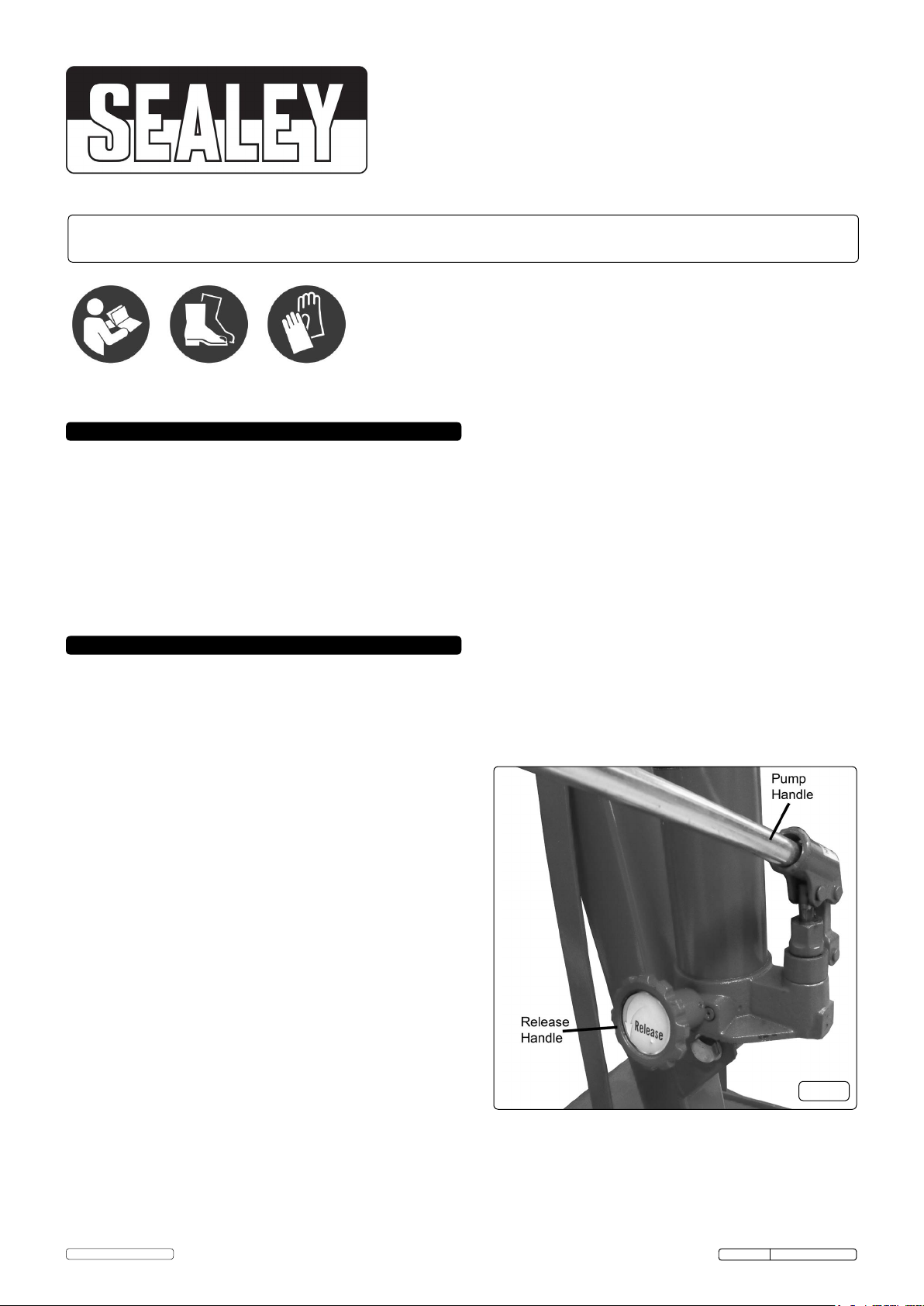
e) For control system, see Fig.1 for release valve and pump handle
assy. Usage is explained in Section 5 Operation.
f) For ground condition requirements, see Section 3 Safety.
g) For information on parts and materials requiring specialised
repair techniques see Section 6 Maintenance.
© Jack Sealey Limited
Original Language Version
Page 1
fig.1
Fig.1
PH10.V5 Issue: 1 - 02/03/16
Page 2

3. SAFETY
3.1 SAFETY
3 Keep crane, lifting slings, support and beams in good working order and condition. Follow the inspection requirements as
described in Section 6 page 3 Maintenance. Take immediate action to repair or replace damaged parts by contacting your
supplier. Ensure that all accessory lifting devices are suitably certified. If crane is damaged, remove from service immediately.
3 Ensure the surface on which the crane is used is level, firm and capable of supporting the weight of the crane with maximum
load - we recommend concrete. Never use the crane on tarmacadam or other soft surfaces.
3 Ensure the crane legs and arms are locked before use and that the adjustable rods are screwed down to the floor.
3 Keep children and unauthorised persons away from the working area.
3 Keep working area clean and tidy, free from unrelated materials and ensure that there is adequate lighting.
3 Ensure that load does not exceed the maximum lifting capacity of the crane. Overloading the crane is dangerous. Where
appropriate, use only the lifting points recommended by the manufacturer of the item to be lifted, e.g. vehicle engine.
3 Before lifting the load ensure that the crane jib is in the lowest practical position, that there are no obstacles which may snag
the load whilst it is being lifted and that the area above the jib is clear.
3 To avoid injury, be fully aware of your own and other persons locations in relation to the lifting, and lowering, of the load.
3 Keep a sound footing and balance, and ensure the floor is not slippery.
3 Ensure jib extension locking bolt and nut are in position before lifting.
3 Ensure the centre of gravity always remains inside the crane base.
7 DO NOT harness the load at an angle or use any attachments not verified as fit for purpose.
7 DO NOT allow the load to swing during lifting.
7 DO NOT allow the load to drop suddenly. Lower load with care, ensuring that you are fully aware of the condition of the surface onto
which the load is to be placed.
7 DO NOT load crane beyond its rated capacity for each specified jib extension position as indicated in Section 2 page 1.
The capacity of the crane reduces as the jib is extended.
7 DO NOT position any part of your body beneath the load.
7 DO NOT use the crane to move or transport a load other than for repositioning (see 5.1.f). The crane is a lifting device only.
7 DO NOT apply any sideways pressure to any part of the crane during lifting or when a load is suspended.
7 DO NOT attempt to adjust the safety valve, which has been set and sealed by the manufacturer.
7 DO NOT use this product to perform a task for which it is not designed.
7 DO NOT use whilst under the influence of drugs, alcohol or intoxicating medication.
7 DO NOT climb on the crane.
3 When not in use fold the crane down and store in a safe, dry, childproof area.
3 This crane is designed for lifting within a garage or workshop environment.
WARNING! Failure to heed safety and warning instructions may result in damage and/or personal injury and will invalidate the
warranty.
NOTE: ENSURE YOU HAVE READ AND UNDERSTOOD THE SAFETY INSTRUCTIONS AT THE BEGINNING OF THIS SECTION BEFORE YOU
OPERATE THE CRANE.
4. ASSEMBLY
WARNING! It takes two people to build the crane. Leave all nuts loose until assembly is complete.
Note: refer to attached parts diagram pages 5 & 6.
Unpack and check against parts lists on pages 5 & 6.
4.1. Fix legs (3) to base (1) use bolts (23) for rear hole, which passes through connecting plates (9) and legs (3). Secure with spring
washers (26) and nuts (27). Put pins (8) into front holes of legs, secure with R clips (38).
4.2. Fit rear castors (15). Use bolts (19) from underneath through base (1) then through support straps (7), secure with spring washers (20)
and nuts (21).
4.3. Fitupright(2).Usebolt(32)washer(26)andnut(27)toxthroughuprighttopholeandsupportstraps(7)rst.Supporttheweightof
the upright (2). Fix bottom of upright (2) with bolts (24).
4.4. Fit adjustable rods (10) into front of base (1), secure with R clips (37).
4.5. Fit handle (17) with bolts (22) and spring washers (20).
4.6. Fit boom (4) use bolt (36) washer (28) and nut (30).
4.7. Fit boom extension (5) use pin (8).
4.8 Fit hook (12), use bolt (33), spring washer (28) and nut (27).
4.9. Fithydraulicramunit(6).Fixbottomrst,usebolt(25),washer(29)andnut(30).Fixthetopoftheramusingbolt(31),washer(29)and
nut (30).
4.10. Tighten all nuts and bolts.
4.11. Bleed hydraulic system: Place the pump handle into the pump socket, ensure the release handle is in the open position and pump
the handle 10-15 times, through the full stroke, thus bleeding from the hydraulic system any air which may have entered the system
during transit.
4.12. How to store: Removethefrontpin(8)fromthelegs(30andliftthemtovertical,tostorethelegsinanuprightposition.Retpin(8)
and R clip (38) through the connecting plate (9) to secure. Adjust the adjustable rods (10) to make sure the crane sits upright.
5. OPERATION
5.1 OPERATION. (Refer to Section 6.2 (a) regarding inspection before each and every use).
a) Ensure handwheel is in the raise (fully clockwise position).
b) Place handle into pump socket and pump, the jib will raise. Continue to pump until the jib reaches the height at which the load can be secured.
c) Connect the crane hook to the load using a suitable certified sling or support beam. Ensure you are aware of the load weight,
and check that it is within the capacity of the crane (at the jib extension you are using) and the sling or support beam. When removing
engines ensure you know the weight to be lifted. Use only the lifting points recommended by the vehicle manufacturer.
d) Lift only from directly above the load. WARNING! DO NOT LIFT THE LOAD AT AN ANGLE!
e) To lower load, turn release handwheel VERY SLOWLY anti-clockwise avoiding any sudden movement.
WARNING! Do not allow the load to drop suddenly.
f) The crane is not a transportation device but may be used to reposition the load being worked on. To do so, lower load and jib
with care, to the lowest possible point before attempting to move. Do not try to move crane in a sideways direction. The crane is
not designed to support the load indefinitely. When you have repositioned the load, lower the load onto a secure and
appropriate working base, being fully aware of your own and other persons locations in relation to the lowering load.
g) When load has been secured, remove lifting sling, support beam etc. and place crane in a safe location with lifting beam fully lowered.
© Jack Sealey Limited
Original Language Version
Page 2
PH10.V5 Issue: 1 - 02/03/16
Page 3

6. MAINTENANCE / EXAMINATION / INSPECTION
NOTE: The crane MUST be kept clean and dry and must be maintained in accordance with these instructions.
6.1. Lubrication.
a) Oil all working parts monthly.
b) The ram is filled with oil and should only require occasional topping up. For the occasional top up DO NOT use brake fluid, as this will
damage the hydraulic seals. Proceed as follows:
1) Use only good quality hydraulic jack oil available from your supplier.
2) DO NOT OVERFILL as this will cause failure, with ram in lowered position remove rubber bung located on the ram and top up to
just below the filling hole. Replace rubber bung.
3) After filling with hydraulic oil, pump the crane up to full height and pour off any excess oil.
6.2. Inspection and Examination of Crane Before Use.
a) Before each use of the crane you must perform an inspection for leaks, damage, loose or missing parts.
b) The workshop crane must be examined immediately if it has been subject to an abnormal load or shock. It is recommended
that such an examination is made by an authorised service agent.
c) The owner and/or operator must be aware that repair of this equipment will require specialised knowledge and facilities.
It is recommended that an annual examination of the workshop crane is made by an authorised service agent.
d) Unauthorised parts may be dangerous and will invalidate the warranty.
Note! Please see the Definition of ‘inspection’ and ‘examination’ below.
Inspection:
Looking at the crane for defects and checking the operation of the controls, limiting and indicating devices without loading the crane.
This is much more than a check but does not normally require any part of the crane to be dismantled other than removal or opening
of covers or housings.
Examination:
Verification that the crane can safely continue in service including a functional test of all safety devices i.e. limiting, indicating
equipment, brakes, clutches, safety valves etc to verify that they operate within the required tolerances. An examination is more
thorough than an inspection.
6.3 Storage
a) Always store the crane fully closed so that the jib is in lowest position and the ram is closed.
b) To save space the legs may be folded into the upright position and secured in place using the Lock Pins.
7. OWNER’S & OPERATOR’S RESPONSIBILITIES
The owner and/or operator shall study these instructions and retain them for future use.
a) Understanding instructions and warnings.
The owner and/or operator shall understand the operating instructions and warnings before operating the crane.
Warning information must be emphasised and understood.
If the operator is not fluent in English, the product instructions and warnings must be read to, and discussed with, the
operator in the operator’s native language by the owner, making sure the operator understands the contents.
b) Damaged Cranes.
Any crane which appears to be damaged, badly worn, or operates abnormally MUST BE REMOVED FROM SERVICE!
It is recommended that necessary repairs be made by an authorised service agent.
c) End of service.
Through years of normal wear, the crane will eventually become unserviceable. When this happens ensure the hydraulic oil is drained
off and disposed of in accordance with local authority regulations.
Recycle unwanted materials instead of disposing of them as waste. All tools, accessories and packaging should be
Environmental Protection
sorted, taken to a recycling centre and disposed of in a manner which is compatible with the environment.
When the product becomes completely unserviceable and requires disposal, drain off any fluids (if applicable)
into approved containers and dispose of the product and the fluids according to local regulations.
NOTE: It is our policy to continually improve products and as such we reserve the right to alter data, specifications and component parts without prior notice.
IMPORTANT: No liability is accepted for incorrect use of this product.
WARRANTY: Guarantee is 12 months from purchase date, proof of which will be required for any claim.
© Jack Sealey Limited
Sole UK Distributor, Sealey Group,
Kempson Way, Suffolk Business Park,
Bury St. Edmunds, Suffolk,
IP32 7AR
Page 3
Original Language Version
01284 757500
01284 703534
www.sealey.co.uk
sales@sealey.co.uk
PH10.V5 Issue: 1 - 02/03/16
Page 4

8. DECLARATION OF CONFORMITY
EC DECLARATION
OF CONFORMITY
Description and Function: ������������������������������������������������������������������������������������������������������������������������������������������������������������������������
Model/Type: ���������������������������������������������������������������������������������������������������������������������������������������������������������������������������������������������
Manufacturing Date/Serial Number (optional): ����������������������������������������������������������������������������������������������������������������������������������������
: 2006/42/EC Machinery Directive
2006/95/EC Low Voltage Directive
2004/108/EC EMC Directive
2009/125/EC Ecodesign Requirements
2009/142/EC Gas Appliance Directive
2009/105/EC Simple Pressure Vessels Directive
Manufacturer’s authorised representative within the EC: Jack Sealey Ltd, Kempson Way, Suffolk Business Park, Bury St
Edmunds, Suffolk. IP32 7AR
Conforms to the requirements of the Directives, as indicated�
And the following harmonised standard(s)
������������������������������������������������������������������������������������������������������
������������������������������������������������������������������������������������������������������
Low Prole Engine Crane 1tonne
PH10.V5
2000/14/EC Noise Emission in the Environment Directive
2012/19/EU WEEE Directive
2011/65/EU RoHS Directive
97/23/EC Pressure Equipment Directive
89/686/EEC PPE Directive
1999/5/EC RTTE Directive
������������������������������������������������������������������������������������������������������
������������������������������������������������������������������������������������������������������
������������������������������������������������������������������������������������������������������
������������������������������������������������������������������������������������������������������
������������������������������������������������������������������������������������������������������
Technical le compiled by: Jack Sealey Ltd
Being the responsible person appointed by the manufacturer.
Signed �������������������������������������������������������������������������������������������
Date �����������������������������������������������������������������������������������������������
Name ���������������������������������������������������������������������������������������������
Position �����������������������������������������������������������������������������������������
Place: Bury St Edmunds
1 March 2016
Steve Buckle�
Marketing Director�
Sealey Power Products Kempson Way, 01284 757500 01284 703534 sales@sealey�co�uk www�sealey�co�uk
Suffolk Business Park, Bury St Edmunds,
Suffolk� IP32 7AR
�����������������������������������������������������������������������������������������������������-
������������������������������������������������������������������������������������������������������
������������������������������������������������������������������������������������������������������
© Jack Sealey Limited
Page 4
Original Language Version
PH10.V5 Issue: 1 - 02/03/16
Page 5

PARTS FOR :
LOW PROFILE ENGINE CRANE 1tonne
MODELS: PH10.V5
ISSUE NO : 1
ISSUE DATE : 01/03/2016
ITEM PART NO DESCRIPTION ITEM PART NO DESCRIPTION ITEM PART NO DESCRIPTION
1 PH10.V4-01 FRAME BASE 14 PH10.V4-14 FRONT WHEEL SLEEVE 27 PH10.V4-27 NUT M14
2 PH10.V4-02 UPRIGHT 15 PH10.V4-15 3-1/2"SWIVEL WHEEL 28 PH10.V4-28 FLAT WASHER
3 PH10.V4-03 LEFT & RIGHT LEG 16 PH10.V4-16 FRONT WHEEL WASHER 29 PH10.V4-29 FLAT WASHER
4 PH10.V4-04 BOOM + COVER 17 PH10.V4-17 HANDLE 30 PH10.V4-30 NUT M16
5 PH10.V4-05 BOOM EXTENSION + COVER 18 PH10.V4-18 NUT M12 31 PH10.V4-31 BOLT M16 X 75
6 PH10.V4-06 HYDRAULIC RAM 19 PH10.V4-19 BOLT M8 X 20 32 PH10.V4-32 BOLT M14X100
7 PH10.V4-07A SUPPORT STRAP (FLAT PLATE WITH 4 BOLT HOLES) 20 PH10.V4-20 WASHER 8M 33 PH10.V4-33 BOLT M14X90
8 PH10.V4-08 LOCATING PIN 21 PH10.V4-21 NUT M8 34 PH10.V4-34 BOLT M12X80
9 PH10.V4-09 SUPPORT BRACE 22 PH10.V4-22 BOLT M8X12 35 PH10.V4-35 SPRING WASHER
10 PH10.V4-10 ADJUSTABLE ROD ASSEMBLY 23 PH10.V4-23 BOLT M14X110 (8.8) 36 PH10.V4-36 BOLT M16X110
11 PH10.V4-11 HANDLE ASSEMBLY 24 PH10.V4-24 BOLT M14 X 80 PH10.V4-FK FIXING KIT
12 PH10.V4-12 HOOK ASSEMBLY 25 PH10.V4-25 BOLT M16 X 90
13 PH10.V4-13 FRONT WHEEL 26 PH10.V4-26 SPRING WASHER 14mm
1 OF 2
Page 6

PARTS FOR :
LOW PROFILE ENGINE CRANE 1tonne
MODELS: PH10.V5
ITEM PART NO DESCRIPTION ITEM PART NO DESCRIPTION
1 PH10.V4-P01 PISTON ROD 22 PH10.V4-P22 TOP CUP
2 PH10.V4-P02 STEEL WIRE WASHER 23 PH10.V4-P23 RECTANGLE RING
3 PH10.V4-P03 PLUNGER 24 PH10.V4-P24 RESERVOIR
4 PH10.V4-P04 BOOM EXT. COVER 25 PH10.V4-P25 OIL FILLING
5 PH10.V4-P05 Y-RING 26 PH10.V4-P26 TRAPEZIUM RING
6 PH10.V4-P06 STEEL WIRE WASHER 27 PH10.V4-P27 BASE
7 PH10.V4-P07 CYLINDER 28 PH10.V4-P28 NYLON WASHER
8 PH10.V4-P08 STEEL WASHER 29 PH10.V4-P29 HEX BOLT M6X10
9 PH10.V4-P09 FILTER OIL TUBE 30 PH10.V4-P30 RELEASE VALVE BODY
10 PH10.V4-P10 STEEL BALL 6.0mm 31 PH10.V4-P31 RELEASE VALVE
11 PH10.V4-P11 WASHER 32 PH10.V4-P32 BUSH
12 PH10.V4-P12 PUMP CYLINDER 33 PH10.V4-P33 TORSION SPRING
13 PH10.V4-P13 J-RING 34 PH10.V4-P34 SPRING COLUMN PIN
14 PH10.V4-P14 O-RING 35 PH10.V4-P35 HANDWHEEL
15 PH10.V4-P15 PUMP PLUNGER SEAL 36 PH10.V4-P36 STEEL BALL 3.0mm
16 PH10.V4-P16 PUMP PLUNGER 37 PH10.V4-P37 SPRING BASE
17 PH10.V4-P17 PIN 38 PH10.V4-P38 SAFETY VALVE SPRING
18 PH10.V4-P18 TORSION SPRING PIN 39 PH10.V4-P39 O-RING
19 PH10.V4-P19 HANDLE SOCKET 40 PH10.V4-P40 PLUG SCREW
20 PH10.V4-P20 HANDLE 41 PH10.V4-P41 HANDLE SOCKET BASE
21 PH10.V4-P21 O-RING
ISSUE NO : 1
ISSUE DATE : 01/03/2016
2 OF 2
 Loading...