

Page 1
INSTRUCTIONS FOR:
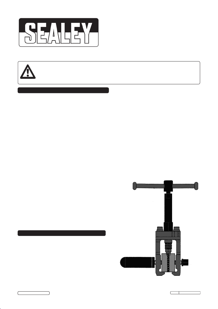
ON CAR HYDRAULIC
PIPE FLARING TOOL
MODEL No: PFT10
Thank you for purchasing a Sealey Product. Manufactured to a high standard this product will, if used according to these
instructions and properly maintained, give you years of trouble free performance.
IMPORTANT: PLEASE READ THESE INSTRUCTIONS CAREFULLY. NOTE THE SAFE OPERATIONAL
REQUIREMENTS, WARNINGS AND CAUTIONS. USE THIS PRODUCT CORRECTLY AND WITH CARE, FOR THE
PURPOSE FOR WHICH IT IS INTENDED.
FAILURE TO DO SO MAY CAUSE DAMAGE AND/OR PERSONAL INJURY AND WILL INVALIDATE THE WARRANTY.
PLEASE KEEP THESE INSTRUCTIONS SAFE FOR FUTURE USE.
1. SAFETY INSTRUCTIONS
WARNING! Ensure Health & Safety, local authority and general workshop practice requirements are
adhered to when using this equipment. Familiarise yourself with the application and limitations, as well as
the potential hazards of the kit.
This kit is suitable for flaring copper, brass, steel or thin walled aluminium pipe.
Maintain the kit in good condition.
Replace or repair damaged parts. Use genuine parts only. Unauthorised parts may be dangerous and will
invalidate the warranty.
Locate the flaring tools in a suitable work area, keep the area clean and tidy and ensure there is adequate
lighting.
WARNING! Always wear approved eye or face protection when using the flaring tools.
Keep children and unauthorised persons away from the working area.
DO NOT use the kit for any purpose other than for which it is designed.
DO NOT use the kit if any parts are damaged or missing as this may cause failure and/or personal injury.
DO NOT allow untrained persons to use the kit.
DO NOT attempt to flare piping when you are tired, under the influence of alcohol, drugs or intoxicating
medication.
When not in use clean kit components, replace in case and
store in a safe, dry, childproof area.
Remember! The safe operation of a vehicle, or other
equipment, may well depend on the quality of the flare
produced. Discard any flare which is mis-formed or cracked in any way.
WARNING! The warnings, cautions and instructions discussed in this
manual cannot cover all possible conditions and situations that may occur.
It must be understood that common sense and caution are factors which
cannot be built into this product, but must be applied by the operator.
2. INTRODUCTION & SPECIFICATIONS
Produces accurate automotive SAE and DIN flares
on 3/16” and 4.75mm pipes respectively. Small body
makes it ideal for splicing in replacement sections of
brake pipe on-vehicle. Features a hydraulic ram
which also makes it suitable for steel pipes.
Part Description
Dies: 3/16” SAE, 4.75mm DIN.
© Jack Sealey Limited
Original Language Version
PFT10 Issue: 2(L) - 29/11/13
Page 2
3. OPERATING INSTRUCTIONS
WARNING! Before using the flaring kit, ensure that you `
have read and understood the Safety Instructions
in Section 1.
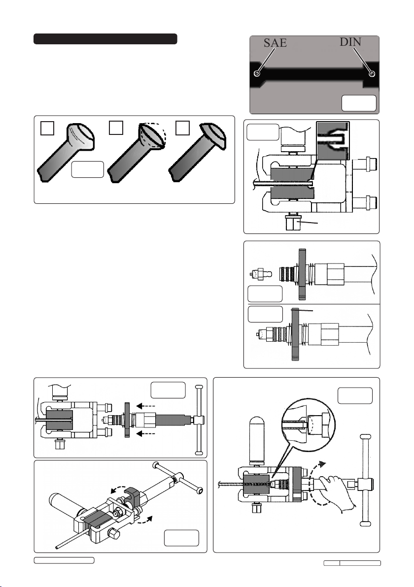
3.1. The pipe end to be flared must be cut clean, square
and be de-burred. Use a pipe or tube cutter (available from
your Sealey dealer).
SAE
4.75mm
BLOCK
DIN
fig.1
A
B
C
fig.3
BUBBLE (MALE)
FLARE
(SAE)
3.2. Select the clamp block. For SAE male and female flares
(fig.3 A & B above) use the SAE marked side of the blocks
(fig.1) and SAE marked dies. For a DIN flare (fig.3 C
above) select the DIN side of the block and the DIN die.
3.3. Lay the pipe on the block, place the other half of the block
on top of the pipe and insert into tool as fig.2. Ensure that
the pipe is just inside the end of the block, clamp the
assembly in place using lock bolt (fig.2).
3.4. To form a Bubble (Male) flare SAE (fig.3.A).
First select the concave SAE die (fig.4) and insert it into the
locking collar on the ram (fig.5). Ensure the T-bar is fully
unwound (anticlockwise).
3.4.1. Adjust the lock plate (fig.5) half way along the thread and
insert the ram into the main tool body (fig.6).
3.4.2. Swivel the locking plate into position (fig.7) and tighten
the ram body ensuring the die tip locates in the pipe (fig.8).
DOUBLE (FEMALE)
FLARE
(SAE)
SINGLE (MALE)
FLARE
(DIN)
fig.6
fig.2
fig.4
fig.5
LOCK BOLT
LOCK PLATE
fig.8
© Jack Sealey Limited
fig.7
Original Language Version
PFT10 Issue: 2(L) - 29/11/13
Page 3

3.4.3. Rotate the T-bar clockwise forcing the die into the pipe
(fig.9). Continue to turn until the resistance significantly
increases, undo the T-bar a couple of turns and remove the
fig.9
fig.1
ram assembly from the main body.
3.4.4. Remove the block and pipe from the main body (unless you
wish to make a double flare (fig.3B)) and separate the block
from the pipe, check that the flare has no cracks and is
symmetrically formed.
3.5. To form a Double (Female) flare SAE (fig.3.B).
3.5.1. Leave the pipe in the block after completing the bubble flare.
3.5.2. Change the die to the SAE convex die (fig.10).
This will fold the top section of the bubble flare inwards to
fig.10
form a double flare (fig.3.B).
3.5.3. Follow the same procedure as described in 3.4 to 3.4.4.
Again, check that the flare is symmetrically formed.
3.6. To form a Single Flare DIN (fig.3C).
3.6.1. Follow the procedures laid out in 3.4 to 3.4.4, only this time
select the DIN side of the block (fig.1) and the DIN concave
die.
fig.11
3.7. Adaptor Driver (fig.11).
For jobs where restricted space makes use of the
hydraulic ram difficult, use the 23mm adaptor driver
in place of the ram.
WARNING! The safe operation of a vehicle, or other equipment, may well depend on the
quality of the flare produced. Discard any flare which is misformed or cracked in any way.
Parts support is available for this product. To obtain a parts listing and/or diagram, please
log on to www.sealey.co.uk, email sales@sealey.co.uk or phone 01284 757500.
NOTE: It is our policy to continually improve products and as such we reserve the right to alter data, specifications and component parts without prior notice.
IMPORTANT: No liability is accepted for incorrect use of this product.
WARRANTY: Guarantee is 12 months from purchase date, proof of which will be required for any claim.
INFORMATION: For a copy of our latest catalogue and promotions call us on 01284 757525 and leave your full name and address, including postcode.
© Jack Sealey Limited
Sole UK Distributor, Sealey Group,
Kempson Way, Suffolk Business Park,
Bury St. Edmunds, Suffolk,
IP32 7AR
Original Language Version
01284 757500
01284 703534
www.sealey.co.uk
Web
sales@sealey.co.uk
email
PFT10 Issue: 2(L) - 29/11/13
 Loading...