

Page 1

Thank you for purchasing a Sealey product. Manufactured to a high standard this product will, if used according to these instructions and properly
maintained, give you years of trouble free performance.
1. SAFETY INSTRUCTIONS
INSTRUCTION MANUAL f O R :
PETROL PRESSURE WASHER
MODEL NO : PCM2500.V2
IMPORTANT: PLEASE READ THESE INSTRUCTIONS CAREFULLY. NOTE THE SAFE OPERATIONAL REQUIREMENTS, WARNINGS & CAUTIONS.
USE THE PRODUCT CORRECTLY AND WITH CARE FOR THE PURPOSE FOR WHICH IT IS INTENDED. FAILURE TO DO SO MAY CAUSE
DAMAGE AND/OR PERSONAL INJURY AND WILL INVALIDATE THE WARRANTY. PLEASE KEEP INSTRUCTIONS SAFE FOR FUTURE USE.
GENERAL SAFETY
WARNING! RISK OF FLUID INJECTION. This washer operates at fluid pressures and velocities high enough to penetrate human
and animal flesh. If there is an occurrence of fluid injection seek medical help immediately
WARNING! Stop the engine and disconnect the mains water supply before changing accessories or performing any maintenance.
WARNING! Do not operate the washer if damaged. Replace or repair using recommended parts only. Unauthorised parts may
be dangerous and will invalidate your warranty. Use authorised Service agent only.
Keep the washer in good condition. Regular maintenance will give the best and safest performance.
Ensure you comply with the water supply company regulations before connecting to the mains. If you are connecting to the mains drinking
water supply ensure you have a back flow preventer valve installed.
The water supply hose must be reinforced and have an internal diameter of 13mm (1/2”). The minimum water supply rate must be at least
equal to the cleaner capacity. The water temperature must not exceed 600C, and the pressure must not exceed 10bar.
WARNING! DO NOT operate the washer without the water supply connected. To do so will damage the machine.
Position the washer as near as possible to the mains water supply.
Only use recommended washing detergents. Failure to do so may cause corrosion to equipment and hoses.
WARNING! Use the washer on a flat, level surface, in a horizontal position. Failure to do so will invalidate your warranty.
Wear safety goggles and adequate protective clothing, and anti-slip rubber soled footwear.
WARNING! The high pressure jet must be used with caution. Ensure you aim the lance correctly at the work surface. Failure to do so may
scatter loose particles at the same force as the water pressure, resulting in possible damage or personal injury.
Keep all persons and animals at a safe distance from the hose working area. It is difficult to give an exact safe distance as it will depend
upon your circumstances. We recommend at least 15 metres (16 yards). Also ensure other persons are aware before you start to depress
the washer trigger.
Hold the gun firmly for it will tend to “kick” backwards when you first pull the trigger.
DO NOT allow children or untrained persons to operate the washer.
DO NOT connect other appliances to the washer inlet or outlet. Only use the supplied or recommended outlet nozzle.
DO NOT use the washer if the water supply hose is damaged. Also check that the hose is laid out straight and safely.
DO NOT jam the operating trigger in the operating position, and DO NOT pull the trigger without holding and aiming the gun correctly.
WARNING! DO NOT attempt to alter the pressure regulating valve as this may cause serious damage.
DO NOT move the washer by pulling on the high pressure hose or the mains water supply hose. Use the machine handle.
DO NOT direct jet against yourself, other persons or animals, electrical equipment or the machine itself.
WARNING! DO NOT leave the engine running for more than 2 minutes without operating the trigger, as temperature/pressure increase
may damage the sealing system.
DO NOT use the washer if you are tired or under the influence of alcohol, drugs or intoxicating medication.
Ensure that the hose pressure is discharged before disconnecting the mains water hose.
When not in use, disconnect from the water supply. Clean and dry the washer and store in a safe, dry, childproof area.
DO NOT allow the machine to become frozen.
ENGINE SAFETY
WARNING! Check the engine oil level before each startup. Only use an approved oil and never operate the engine with insufficient oil.
WARNING! DO NOT touch spark plug or plug lead with wet (or dry) hands whilst the engine is running - severe, potentially fatal,
electric shock may result.
For safety instructions relative to the maintenance and use of the petrol engine refer to the engine instruction manual.
DO NOT check ignition system by removing the spark plug or spark plug lead. Use specific tester or contact service agent.
DO NOT operate the washer in an enclosed area as the motor exhaust fumes are a health hazard.
DO NOT use the washer with flammable, toxic or corrosive liquids.
DO NOT leave the washer unattended whilst operating, and DO NOT remove the fuel cap whilst the engine is running.
DO NOT refuel the engine whilst it is running. Stop the engine and allow it to cool for two minutes before attempting to refuel.
DO NOT refuel in a closed or poorly ventilated environment as there is a danger of explosion or fire. Refuel out doors.
DO NOT smoke or place the washer near any naked flames whilst re-fuelling.
DO NOT operate washer if there is a fuel leak. Move the unit and avoid any combustion until the leak has been fixed and the machine is dry.
DO NOT start the engine if there are any flammable materials near the exhaust system or in the path of the exhaust gases.
DO NOT block the engine ventilation grilles.
Ensure engine fuel is stored in an approved container.
For long term storage ensure the fuel is drained and that the washer is adequately protected against frost.
DO NOT operate the engine with either the silencer or air filter removed.
DO NOT touch the engine during or after use. To avoid burns allow it to cool before handling.
2. SPECIFICATION & INTRODUCTION
Model No: ............................... PCM2500.V2
Output Pressure: ...............................2500psi
Flow Rate: ................................... 600ltr/hr
Hose Length: ...................................5.0mtr
Nozzle: . . . . . . . . . . . . . . . . . . . . . . . . .Adjustable spray pattern
Maximum Inlet Temperature: ........................60°C
Engine Type: ............... 4 Stroke, single cylinder, petrol
Engine Capacity: ................................ 196cc
Engine Power ..................4.8kW(6.5hp) @ 3600rpm
Starting: .......................................Recoil
Fuel Tank: . . . . . . . . . . . . . . . . . . . . . . . . . . . . . . . . . . . . . . 3.6ltr
Fuel . . . . . . . . . . . . . . . . . . . . . .Lead free petrol, 85Ron Min
Fuel Consumption: . . . . . . . . . . . . . . . . . . . . . . . . .2.1 - 2.6ltr/hr
Weight: . . . . . . . . . . . . . . . . . . . . . . . . . . . . . . . . . . . . . . . . 35kg
Original Language Version
PCM2500.V2 Issue: 2 - 13/10/11
Page 2
3. ASSEMBLY / PRE-OPERATION
Unpack contents and check to ensure all parts are in good
condition. If you experience any problems contact your
dealer immediately.
3.1 ASSEMBLY.
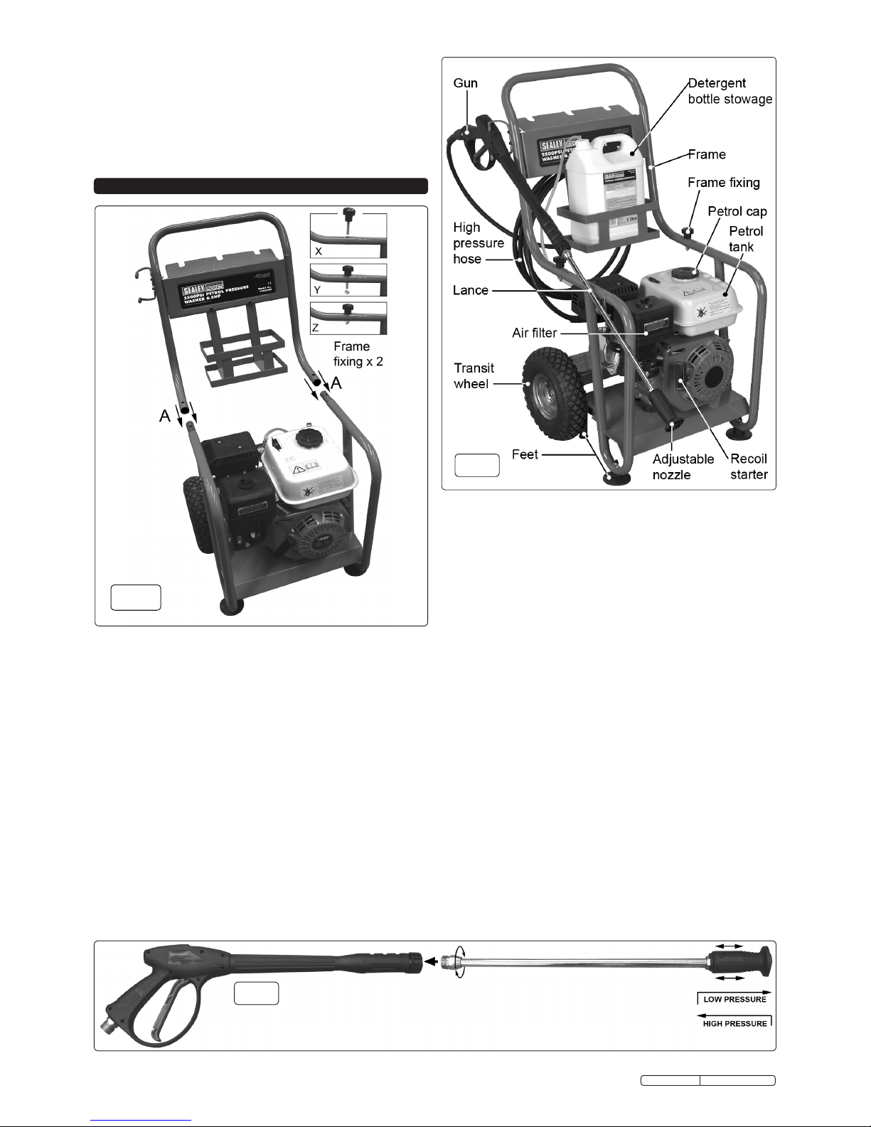
3.1.1 Attach the upper frame to the lower frame by pushing it onto the
spigots protruding from the lower frame as indicated at ‘A’ in fig.1
above. Ensure that the holes in the ends of the upper frame align
with the holes in the spigots. Secure the two parts of the frame
together by screwing a frame fixing through each joint as indicated in
the inset pictures (fig.1X&Y). Tighten both fixings by hand using the
black knobs. Lock each fixing using a nyloc nut applied to the thread
protruding from the underside of each joint. (fig.1Z)
3.1.2 Slide each wheel onto the axle stubs and retain with a washer and
13mm nut.
3.1.3 Screw together the two halves of the lance as shown in fig.3.
3.1.4 Attach the high pressure hose to the water inlet on the gun
handle as shown in fig.4A and B.
3.1.5 Attach the other end of the high pressure hose to the pump
outlet as shown in fig.5.
3.1.6 Connect the mains water supply hose to the pump inlet as
shown in fig.5. USE COLD WATER ONLY.
fig.3
Introduction:
Petrol powered pressure washer with recoil starting. Ideal for
commercial applications with 5mtr pressure hose, 1mtr gun and lance
and adjustable nozzle. Low-pressure liquid detergent injection system
with provision for detergent bottle stowage. Safety latch on trigger and
automatic low-oil engine shutdown reduce risks of misuse and
equipment damage. Unit stands on four legs, two with sucker feet to
prevent creep, and tilts back onto two pneumatic tyred wheels for
moving. Supplied with tools and full Instructions.
fig.2
fig.1
Note: The water supply hose must be reinforced and have an
internal diameter of 13mm (1/2”). The minimum water
supply rate must be at least equal to the washer flow rate.
3.2 DETERGENT DELIVERY.
3.2.1 Remove the cap from a bottle of detergent and place the bottle
into the stowage frame as shown in fig.2.
3.2.2 On the top of the pump outlet is a brass siphon injection fitting.
Push the detergent input pipe onto the fitting (fig.5) and place the
filter on the other end into the container of detergent. When
the nozzle on the lance is set to low pressure, detergent will be
drawn from the container by siphonic action and will mix
automatically with the water from the pump. Use Sealey General
Purpose Detergent, AK130 (25ltr) or AK131 (5ltr). Traffic Film
Remover is also available, AK132 (25ltr) or AK133 (5ltr).
3.3 NOZZLE CONTROL.
3.3.1 PRESSURE. To change from high pressure to low pressure the
whole nozzle moves backwards and forwards by about 8mm on
the end of the lance. Pull the nozzle back towards the handle
for high pressure and push it away from the handle for low
pressure (see fig.3).
3.3.2 SPRAY PATTERN. To change the spray pattern from a pencil
jet to a fan jet rotate the nozzle as shown in fig.6.
3.4 ENGINE LUBRICATION.
3.4.1 The pressure washer engine is shipped from the factory without
oil. Do not attempt to start the engine before the sump has
been filled with the correct amount of oil. Refer to the section 7.2.
3.5 FUEL.
3.5.1 Fill the petrol tank with fresh unleaded petrol. Keep fuel level
on or below the fuel level indicator in the fuel filter which sits in
the neck of the tank.
Original Language Version
PCM2500.V2 Issue: 2 - 13/10/11
Page 3

fig.5
fig.4
fig.6
4. SAFETY FEATURES
4.1 THERMAL RELIEF VALVE.
4.1.1 A thermal relief valve is fitted to protect the machine from
overheating if the gun remains closed for an extended period
of time or if the nozzle becomes blocked. To prolong the life of
the washer every effort should be made to avoid overheating.
It is recommended that if the unit is not to be used for two
minutes or more it should be switched off.
4.2 TRIGGER LOCK.
4.2.1 To prevent accidental starting of the pressure washer the trigger
can be locked as shown in Fig.4B by hinging out the lever built
into the back of the trigger and pressing it until it snaps into an
indent in the handle. To release the locking lever flex the trigger
handle forwards and flip the lever out of the indent and fold it
back into the trigger. The trigger should be locked whenever the
washer is not in use.
4.3 LOW OIL SHUTDOWN.
4.3.1 The engine on this washer is equipped with a low oil shutdown
feature which stops the engine if the oil drops below the
specified level. Should the engine cut out, first check that it is
standing on a level surface. If the oil level is still low top it up as
described in Section 7.2.
5. OPERATION
WARNING! RISK OF FLUID INJECTION. This washer
operates at fluid pressures and velocities high enough to
penetrate human and animal flesh. If there is an occurrence
of fluid injection seek medical help immediately.
WARNING! Ensure you read, understand and apply
Section 1 safety instructions.
WARNING! Dry running can seriously damage the unit.
WARNING! DO NOT leave motor running for more than
2 minutes without operating the trigger, as
temperature/pressure increase may damage sealing system.
5.1. STARTING PROCEDURE.
5.1.1 Check engine oil level before each use.
5.1.2 Check that the mains water feed hose is laid straight, and
then fully open the water tap. Check to ensure there are no
leaks from hoses or connections.
5.1.3 Place the detergent input tube into the detergent container
(Fig.2) Ensure that the filter goes to the bottom of the
container.
5.1.4 Release gun trigger safety catch and depress trigger to allow
any air left in the system to escape, hold for 10 seconds and
release.
5.1.5 Rotate the engine switch clockwise to the ON position. See fig.7.
5.1.6 Fig.8 shows the fuel tap in the OFF position. Push the fuel tap
lever to the right to the ON position.
5.1.7 If starting the engine from cold move the choke lever fully to
the left. Fig.8 shows the lever in the OFF position.
5.1.8 Fig.8 shows the throttle lever in the slow running position.
Move the throttle lever to the left by a small amount.
5.1.9 To start the engine give a steady pull on the starting handle
whilst keeping the trigger pressed until the engine starts and
water flows from the nozzle.
5.1.10 As the engine warms up move the choke lever right into the
‘run’ position.
5.1.11 Adjust the speed
of the engine
using the throttle
lever.
5.2. NOZZLE
SPRAY
ADJUSTING
(FIG 6).
Adjust the
nozzle pressure
and spray
pattern as
described in
section 3.3.
CAUTIONS!
a) Avoid
sudden bursts
of water as this
will cause the
water pressure
to drop and put
extreme
pressure on the
hoses and
connections.
b) If another
person is using
water from the
same supply as
the washer, the
water pressure
will drop and
the washer will
not operate
correctly.
Switch the
engine off
immediately
and wait until
the pressure is
restored.
fig.7
fig.8
Original Language Version
PCM2500.V2 Issue: 2 - 13/10/11
Page 4

fig.10
7.2 CHECKING THE OIL LEVEL. Ensure the unit is on a level surface.
7.2.1 Unscrew the dipstick and wipe it clean of oil. Note that the
maximum oil level should be just below the opening of the filler
neck.
7.2.2 Check the oil level by seating the dipstick into the hole without
screwing it in. See fig.8 above. If there is no oil on the dipstick
when it is removed the level is too low and should be topped
up immediately with an SAE10W - 30 oil.
7.2.3 Top up oil if necessary and recheck level.
7.2.4 Screw dipstick fully home to seal oil fill hole.
Note: The engine is fitted with a low oil sensor which will
automatically shut the engine down in a low oil situation. The
sensor may also operate if the unit is not on a level surface.
7.3 ENGINE STORAGE. If the unit is not to be used for more than
one month the following procedure should be followed.
7.3.1 Top-up engine oil to maximum.
7.3.2 Drain petrol from the fuel tank, fuel line, fuel tap and carburettor.
7.3.3 Pour one teaspoon of engine oil through the spark plug hole, pull
the recoil starter several times and replace the spark plug. Then
pull the starter slowly until an increase in pressure is felt
indicating that the piston has commenced its compression stroke
and leave it in this position. This closes both the intake and
exhaust valves and prevents the inside of the cylinder from
rusting.
7.3.4 Cover the unit and store it in a clean dry place that is well
ventilated and away from open flame or sparks.
7.4 AIR CLEANER. The air cleaner is situated between the fuel tank
and the frame, see fig.2. To access the air cleaner element
unscrew and remove the wing nut on the top of the cover. Pull off
the black cover to reveal the element as shown in fig.11.
Unscrew the wing nut from the top of the filter element and pull
the element off the threaded rod.
7.4.1 Remove the foam sleeve from the outside of the element and tap
the element on a hard surface to dislodge any dust accumulations
from the paper part of the element. If compressed air is available
it can be used to blow out the element. Do not use a brush as
this will be more likely to force dirt into the paper. If the paper
element is heavily contaminated replace it.
7.4.2 Wash the foam sleeve with a household detergent or a high
flash-point solvent and squeeze dry. When the sleeve is
thoroughly dry soak it in clean engine oil. Squeeze out any
excess oil and stretch the sleeve back over the element. Place
the element back over the threaded rod and make sure it seats
properly onto the base of the air filter casing as seen in fig.12.
Secure the element with a wing nut. Place the outer cover back
over the element and secure it with the other wing nut.
7. MAINTENANCE (ENGINE)
7.1 Change engine oil after the first 8 hours of operation.
Thereafter, change oil monthly or every 50 hours of operation.
Change oil more often if engine is operated under heavy load,
or in high ambient air temperatures. During normal operation,
partially burned fuel, small particles of metal from the cylinder
walls, pistons, bearings and combustion deposits will gradually
contaminate the oil. If the oil is not changed regularly, these
foreign particles can cause increased friction and a grinding
action which shortens the life of the engine. Fresh oil also
assists in cooling. Old oil gradually becomes thick and loses its
cooling ability as well as its lubricating qualities.
6. MAINTENANCE (WASHER)
5.3. CLEANING
5.3.1. Push nozzle forward - LOW PRESSURE - and rotate to fan jet.
Only apply detergent at the low pressure rate.
5.3.2. Depress the trigger to apply the detergent to the dry surface
which is to be cleaned.
Vertical surfaces must be cleaned from the bottom upwards.
5.3.3 When detergent application is complete remove the syphon
tube from the detergent container and place it in a container
of clean water. Run the washer at low pressure to purge the
gun of detergent.
5.3.4. Leave the detergent to act for 1-2 minutes, but do not allow
the surface to dry.
5.3.5. Pull nozzle back - HIGH PRESSURE - and use fan or pencil
jet for washing.
5.3.6. Hold nozzle firmly at least 30cm (12”) from the surface and
commence washing with high pressure clean water. Work
from the bottom upwards, and avoid the water running on to
unwashed surfaces.
5.4 SHUT DOWN PROCEDURE.
5.4.1 When you have finished washing, move the throttle lever to
the right to the slow running position.
5.4.2 Turn off the engine switch and close the fuel tap. Turn off the
mains water supply.
5.4.3 Discharge residual pressure from the washer by pressing the
trigger until no more water comes out of the nozzle.
5.4.4 Engage the trigger safety catch, wipe the washer and store in
a dry, safe, childproof area.
5.5 TRANSIT.
5.5.1 In the upright position the washer stands on four feet and the
two wheels are off the ground. The front feet have suckers
attached which help to eliminate creep. The rear feet are out
of sight between the wheels. To move the unit tip it backwards
on the rear feet until the wheels make contact with the
ground. Keep the unit well tipped back as you move it.
Maintenance should only be performed with the engine turned
off and the unit disconnected from the mains water supply.
6.1 Clean gun nozzle with a suitable rigid piece of wire (fig 7).
Detach lance from gun, remove any dirt from the nozzle head
and rinse with clean water. If this does not improve the flow
from the nozzle it should be replaced.
6.2 Check and clean the water inlet filter every 50 operating
hours. The filter is moulded into a rubber washer. Unscrew
the brass connector from the black fitting on the water inlet on
the pump. Push the black fitting backwards which will
eject the filter/washer and then clean the filter washer. If the
filter is damaged in any way it should be replaced.
6.3 Check and clean the detergent filter at the end of the
detergent input tube on a regular basis.
6.4 WINTER STORAGE: Fill the pump with an antifreeze
mixture before storing in a frost free, safe, dry area for the
winter. Introduce the antifreeze by the following method.
6.4.1 Shut off the water supply and disconnect the supply hose.
Relieve pressure within the pump by squeezing the gun
trigger. Remove the high pressure hose and let all water drain
from it. Hold gun/lance with nozzle downwards and pull
trigger until all water has drained out.
6.4.2 Disconnect the ignition lead from the spark plug.
6.4.3 Connect a short length of garden hose to the water inlet and
using a funnel pour an antifreeze mixture into it.
6.4.4 Pull the recoil starter several times to circulate the antifreeze
through the pump. Continue to add antifreeze and pull the
recoil until antifreeze is expelled from the pump.
fig.9
Original Language Version
PCM2500.V2 Issue: 2 - 13/10/11
Page 5

fig.11
fig.12
WARNING! Petrol is extremely flammable and potentially
explosive. Do not perform maintenance on petrol associated
components where there is any source of ignition present such
as cigarettes, sparks, naked flame or hot sufaces.
7.5 DEPOSIT CUP.
7.5.1 The deposit cup at the base of the fuel tap should be cleaned
out every 6 months or 100 hours depending on which comes
first. Set the fuel tap to OFF by turning it to the left.
7.5.2 Unscrew the deposit cup from the base of the fuel tap and wash
it and the associated ‘O’ ring in a high flash point solvent.
Thoroughly dry the two components and reassemble them to the
base of the fuel tap. Turn the fuel tap on and check for leaks.
7.6 MAINTENANCE SCHEDULE.
7.6.1 Before each use.
Check engine oil level.
Inspect the unit for evidence of oil and fuel leaks.
7.6.2 After the first month or 20 hours only.
Change the engine oil.
7.6.3 Every 50 hours.
Change the engine oil.
7.6.4 Every 6 months or 100 hours.
Change the engine oil.
Inspect and clean air filter.
Clean the deposit cup.
Clean spark plug and check gap.
7.6.5 Every 300 hours.
Replace air cleaner element.
Check valve clearances.
Check idling speed.
Clean spark plug and check gap.
Clean fuel tank fuel filter.
Original Language Version
PCM2500.V2 Issue: 2 - 13/10/11
Page 6

9. TROUBLESHOOTING
PROBLEM POSSIBLE CAUSES REMEDY
Engine will not start Low oil sensor has shut down engine Top up oil to correct level
Engine switch not in the ON position Turn switch ON
Pressure build-up in pump Operate trigger
Engine is overloaded Nozzle partially blocked Clean nozzle
Excessive pressure build-up Return to dealer to have reflux valve adjusted
Engine running but pump not Mains water turned off Turn on mains water
building maximum pressure or has
irregular pressure Unit has been stored in freezing temperatures Thaw out completely including hose, gun and wand
Inadequate water supply MInimum required is 10ltr/min at 20psi
Water inlet filter clogged Clean filter
Kink in water supply hose Straighten hose
Wand nozzle worn or damaged Replace nozzle
Air in pump Run unit with gun open and wand removed until
air is purged
Suction or discharge valve clogged or worn out Clean suction or discharge valves
Bypass valve not operating effectively Clean bypass valve
No intake of chemicals Injection tube not properly attached to unit Push tube firmly onto siphon nozzle
Tube cracked or split Replace tubing
Nozzle set to high pressure Move nozzle to low pressure position
Siphon nozzle blocked Clean nozzle
Trigger will not move Trigger lock engaged Release trigger lock
Water in crankcase High humidity Change oil more frequently
Worn seals Return to Sealey dealer for seal replacement
Noisy operation Worn bearings Return to Sealey dealer for bearing replacement
Air mixed with water Check inlet line for correct size or restriction
Rough/pulsating operation with
Inlet restriction
Check for incorrectly sized plumbing, air leaks, or
pressure drop
blockages
Air mixed with water
Check inlet line for correct size or restriction
High crankcase temperature
Wrong grade of oil
Use recommended oil
Oil level too high / low
Adjust oil level to recommended
NOTE: It is our policy to continually improve products and as such we reserve the right to alter data, specifications and component parts without prior notice.
IMPORTANT: No liability is accepted for incorrect use of this product.
WARRANTY: Guarantee is 12 months from purchase date, proof of which will be required for any claim.
INFORMATION: For a copy of our latest catalogue and promotions call us on 01284 757525 and leave your full name and address, including postcode.
01284 757500
01284 703534
sales@sealey.co.uk
Sole UK Distributor, Sealey Group,
Kempson Way, Suffolk Business Park,
Bury St. Edmunds, Suffolk,
IP32 7AR
www.sealey.co.uk
Web
email
Original Language Version
PCM2500.V2 Issue: 2 - 13/10/11
 Loading...