

Page 1
INSTRUCTIONS FOR:
PROFESSIONAL CONDUIT BENDER
MODEL NO: PCB32.V2
Thank you for purchasing a Sealey product. Manufactured to a high standard, this product will, if used according to these
instructions, and properly maintained, give you years of trouble free performance.
IMPORTANT: PLEASE READ THESE INSTRUCTIONS CAREFULLY. NOTE THE SAFE OPERATIONAL REQUIREMENTS, WARNINGS & CAUTIONS. USE THE
PRODUCT CORRECTLY AND WITH CARE FOR THE PURPOSE FOR WHICH IT IS INTENDED. FAILURE TO DO SO MAY CAUSE DAMAGE AND/OR
PERSONAL INJURY AND WILL INVALIDATE THE WARRANTY. KEEP THESE INSTRUCTIONS SAFE FOR FUTURE USE.
1. SAFETY
Ensure the conduit bender is in sound condition and good working order. Take action for immediate repair or replacement of damaged
parts. Use recommended parts only. The use of improper parts may be dangerous and will invalidate the warranty.
Keep bender and associated parts clean for best and safest performance.
Locate the conduit bender in a suitable, well lit work area.
Keep work area clean and tidy and free from unrelated materials.
Use on level and solid ground, preferably concrete.
Ensure all non-essential persons keep a safe distance whilst the conduit bender is in use.
Maintain correct balance and footing. Ensure the floor is not slippery and wear non slip shoes.
Remove ill fitting clothing. Remove ties, watches, rings and other loose jewellery and contain and/or tie back long hair.
Wear appropriate safety clothing including gloves and eye protection.
Keep hands away from moving parts when bending conduit.
s Caution! Cut conduit edges may be sharp, take care when handling any cut steelwork.
DO NOT operate the conduit bender if damaged.
DO NOT allow untrained persons to operate the conduit bender.
DO NOT operate the conduit bender when you are tired, under the influence of alcohol, drugs or intoxicating medication.
DO NOT use the conduit bender for purposes other than that for which it is intended.
Store conduit bender in a safe, dry, childproof location.
Anchor the conduit bender to the floor or use assistance to prevent the conduit bender from lifting during use.
2. INTRODUCTION
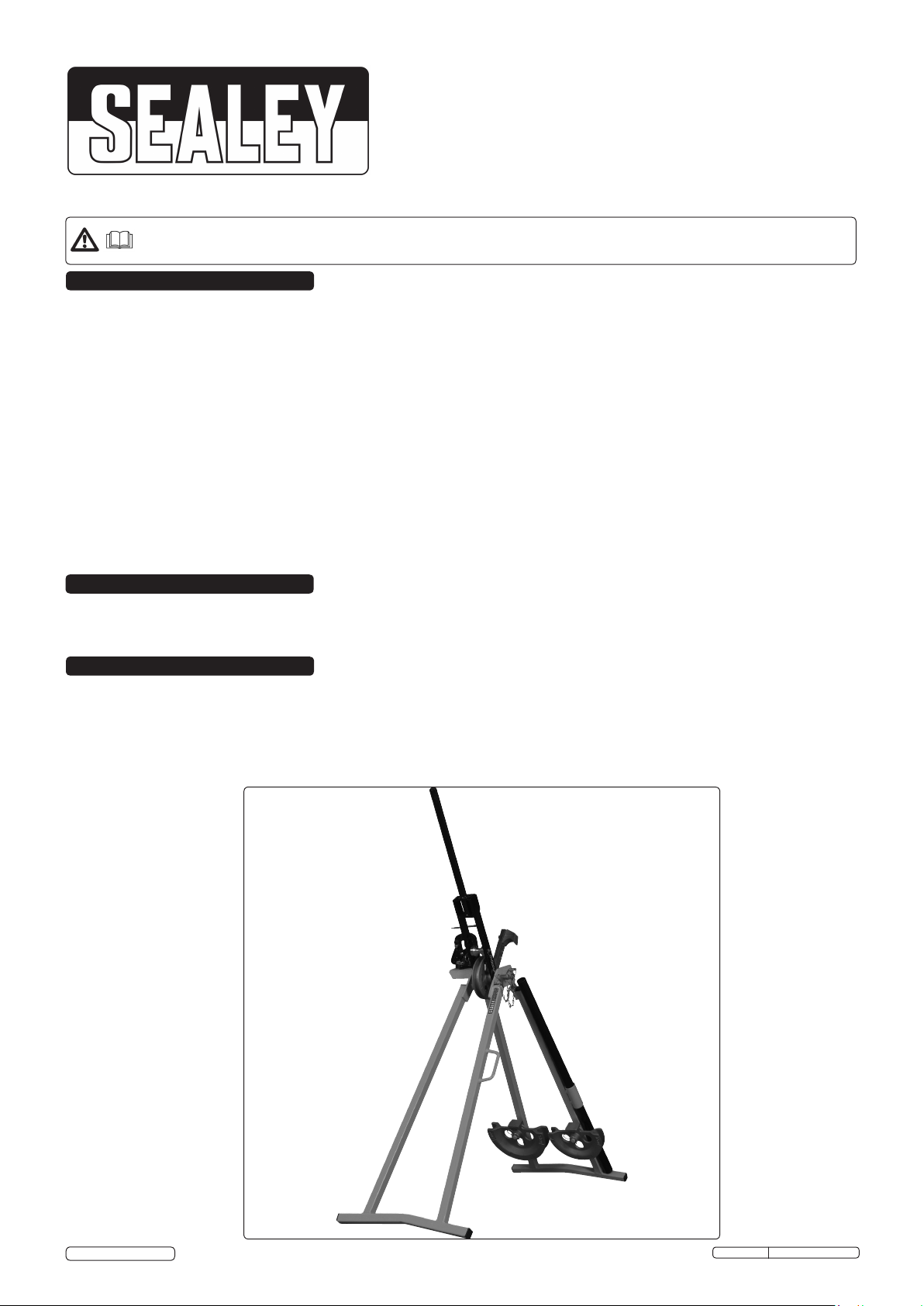
Professional folding A-frame conduit bender with vice. Suitable for galvanised and black enamel conduit. Supplied with three machine cast
formers 20, 25 and 32mm which will bend conduit up to a maximum length of 1100mm. The vice aids cutting lengths and threading.
3. SPECIFICATION
MODEL: ............................................................................. PCB32.V2
Extended (WxDxH): .............................................. 530x1180x1065mm
Folded (WxDxH): ....................................................530x380x1200mm
Former sizes: ............................................................................. 20mm
................................................................................................... 25mm
................................................................................................... 32mm
© Jack Sealey Limited
Original Language Version
PCB32.V2 Issue: 1 - 30/09/14
Page 2
4. ASSEMBLY
WARNING! Ensure that you have read and understood Section 1 Safety Instructions before operating the conduit
bender.
WARNING! When the conduit bender is packed in its box it is heavy and may require 2 people to move it.
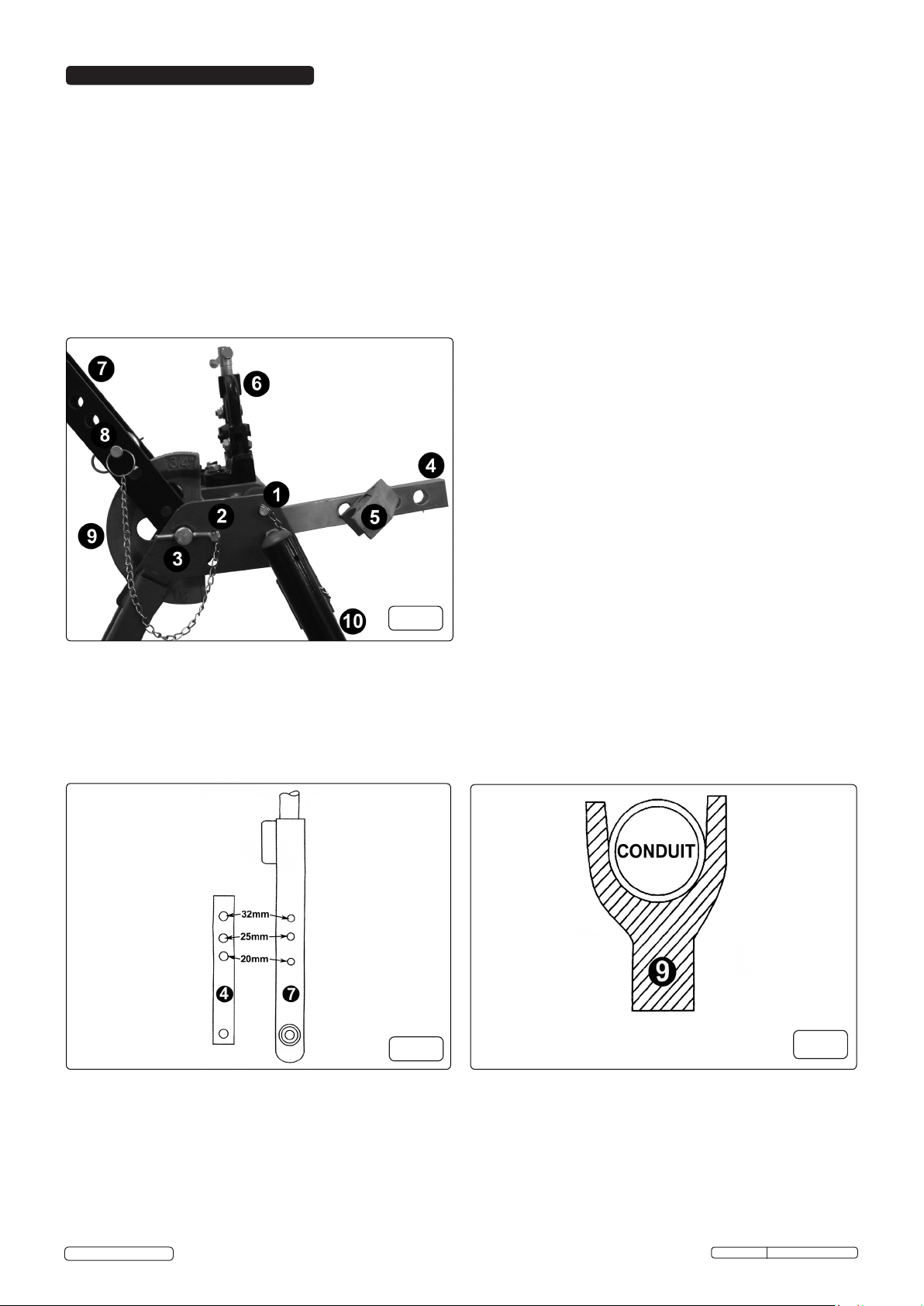
4.1. Remove the conduit bender from the box and check all parts are present. Refer to fig.1.
4.2. Remove the leg retaining pin (1) and open the conduit bender to its fullest extent. Re-insert the leg retaining pin (1) to lock the leg into
position.
4.3. The vice (6) is secured beneath the platform for transit purposes. Remove the 3 retaining bolts and remove the vice (6). Place it on
top of the platform and bolt into position.
4.4. Remove the bending lever retaining pin (2). Fit the former (9) and roller pin (8) in the appropriate position on the bending lever (7)
(fig.2). Secure the roller pin (8) in place with the R-clip.
4.5. Select the size of former (9) required (fig.2) according to the diameter of conduit to be bent. Withdraw the centre pin (3), insert the
former (9) and replace the centre pin (3).
4.6. Raise the bending lever (7) to the upright position and lock in place with the retaining pin (2). Attach the bending lever extension
(10).
4.7. Swing the stop bar (4) to the upright position and insert the stop piece (5) into the appropriate hole required and secure with the
R-clip. The conduit bender is now ready for use.
1.........................Leg retaining pin.
2.........Bending lever retaining pin.
3...................................Centre pin.
4......................................Stop bar.
5.................................. Stop piece.
fig.1
6............................................ Vice.
7..............................Bending lever.
8.................................... Roller pin.
9........................................ Former.
10...........Bending lever extension.
fig.2
fig.3
© Jack Sealey Limited
Original Language Version
PCB32.V2 Issue: 1 - 30/09/14
Page 3

5. OPERATION
5.1. Bending steel conduit.
5.1.1. Pass the conduit through the gap between the stop piece (5) and the former (9) and bed it into the former (fig.3).
5.1.2. Check that the free end of the conduit will not foul on the ground when the bend is complete. The maximum length is 1100mm.
5.1.3. Attach the bending lever extension (10) to the bending lever. Withdraw the bending lever retaining pin (2) and pull the bending lever (7)
down until the required bend is achieved.
5.1.4. If the free end is too long to enable the required bend, remove the conduit, release the bending lever (7) and swing it downwards. Swing
the stop bar (4) downwards.
5.1.5. Load the conduit into the conduit bender as in 4.1.1. Pull the bending lever (7) upwards until the required bend is achieved. Steady the
conduit puller by placing a foot on the cross member when using this method.
5.2. Bending to outside measurements.
Note! The formers are produced to the exact depth and diameter of the tube (fig.3) to facilitate bending to given
measurements.
5.2.1. Measure from the end of the conduit to the distance required and mark accordingly.
5.2.2. Insert the measured part of the conduit into the conduit bender so that it rests against the stop piece (5) and beds into the groove of the
former (9).
5.2.3. Place a square or a rule against the mark on the conduit and slide the conduit along until the square touches the outside edge of the
former (9) (fig.4.A). The conduit is now in the correct position for bending.
Note! Before commencing the bend ensure that the conduit is bedded firmly into the groove in the former (9) otherwise the
bend will be inaccurate.
5.3. Bending to inside measurements.
5.3.1. Measure from the end of the conduit to the distance required and mark accordingly.
5.3.2. Insert the measured part of the conduit into the conduit bender so that it rests against the stop piece (5) and beds into the groove of the
former (9).
5.3.3. Place a square or a rule against the mark on the conduit and slide the conduit along until the square touches the inside edge of the
former (9) (fig.4.B). The conduit is now in the correct position for bending.
5.4. Measuring from a bend.
Note! Use the method explained above to make a bend at a given distance from another bend whether in the same or a different
plane.
5.4.1. If the required measurement is from the outside to the outside of the bends, mark off from the outside of the first bend and square up
with the outside (fig.4.A) of the former (9). If the measurement is from the outside to the inside of the bends (centre to centre) square up
with the inside of the former (fig 4.B).
5.5. Making offsets.
5.5.1. Make the first bend to the required angle. As a guide this should be 45° for offsets measuring 100mm or more and progressively less as
the offset decreases.
5.5.2. Place the bend in the machine as shown in fig.5. Place a straight edge against the outer edge of the former (9) and parallel to the bend.
Adjust the conduit in the machine until the required measurement is obtained.
Note! The offset will increase as the conduit is pushed to the right and decrease as the conduit is pushed to the left.
5.5.3. When the conduit is set correctly ensure that it is firmly bedded into the former. Bend in the normal way until the bends are
parallel with each other.
6. MAINTENANCE
6.1. Check for damage and missing parts before use.
6.2. Regularly oil all moving parts.
6.3. After use store in a safe, dry, childproof location.
4. OPERATION
fig.4
NOTE: It is our policy to continually improve products and as such we reserve the right to alter data, specifications and component parts without prior notice.
IMPORTANT: No liability is accepted for incorrect use of this product.
WARRANTY: Guarantee is 12 months from purchase date, proof of which will be required for any claim.
INFORMATION: For a copy of our latest catalogue and promotions call us on 01284 757525 and leave your full name and address, including postcode.
© Jack Sealey Limited
Recycle unwanted materials instead of disposing of them as waste. All tools, accessories and packaging should be
sorted, taken to a recycling centre and disposed of in a manner which is compatible with the environment.
When the product becomes completely unserviceable and requires disposal, drain off any fluids (if applicable)
into approved containers and dispose of the product and the fluids according to local regulations.
Parts support is available for this product. To obtain a parts listing and/or diagram,
please log on to www.sealey.co.uk, email sales@sealey.co.uk or phone 01284 757500.
Sole UK Distributor, Sealey Group,
Kempson Way, Suffolk Business Park,
Bury St. Edmunds, Suffolk,
IP32 7AR
Environmental Protection
Original Language Version
01284 757500
01284 703534
www.sealey.co.uk
sales@sealey.co.uk
PCB32.V2 Issue: 1 - 30/09/14
fig.5
 Loading...