

Sealey MW131,MW151,MW151PLUS Instructions Manual
MW131
MW151
MW151PLUS
MODELS:
INSTRUCTIONS FOR:
INVERTERS
MW131, MW151, MW151PLUS Issue No.1 24/10/11
INSTRUCTIONS FOR:
INVERTERS
MODEL No's: MW131, MW151, MW151PLUS
Thank you for purchasing a Sealey product. Manufactured to a high standard this product will, if used according to these instructions and properly maintained,
give you years of trouble free performance.
IMPORTANT: BEFORE USING THIS PRO DUC T, PLEAS E READ THE INST RUC TIO NS CAR EF ULLY. MAKE CAR EF UL NOTE OF SAFET Y INST RUC TIO NS,
WARN ING S A ND CAUTI ONS. THIS PRODU CT SHOUL D ONLY BE US ED FO R ITS INTE NDED PURPO SE. FA ILU RE TO DO S O MAY C AUSE DAMAG E
AND/OR PERSONAL INJURY AND WILL INVALIDATE THE WARRANTY. RETAIN THESE INSTRUCTIONS FOR FUTURE USE.
1. SAFETY INSTRUCTIONS
1.1. ELECTRICAL SAFETY
WARNING! It is the responsibility of the owner and the operator to read, understand and comply with the following:
You must check all electrical products, before use, to ensure that they are safe. You must inspect power cables, plugs, sockets and any
other connectors for wear or damage. You must ensure that the risk of electric shock is minimised by the installation of appropriate safety
devices. A Residual Current Circuit Breaker (RCCB) should be incorporated in the main distribution board. We also recommend that a
Residual Current Device (RCD) is used. It is particularly important to use an RCD with portable products that are plugged into a supply
which is not protected by an RCCB. If in any doubt consult a qualified electrician. You may obtain a Residual Current Device by contacting
your Sealey dealer.
You must also read and understand the following instructions concerning electrical safety:
1.1.1. The Electricity at Work Act 1989 requires that all portable electrical appliances, if used on business premises, are tested by a qualified
electrician, using a Portable Appliance Tester (PAT), at least once a year.
1.1.2. The Health & Safety at Work Act 1974 makes owners of electrical appliances responsible for the safe condition of those appliances
and the safety of the appliance operators. If in any doubt about electrical safety, contact a qualified electrician.
1.1.3. Ensure that the insulation on all cables and on the appliance is safe before connecting it to the power supply. See 1.1.1. and 1.1.2.
and use a Portable Appliance Tester.
1.1.4. Ensure that cables are always protected against short circuit and overload.
1.1.5. Regularly inspect power supply cables and plugs for wear or damage and check all connections to
ensure that none are loose.
1.1.6. Important: Ensure that the voltage marked on the appliance matches the power supply to be used
and that the plug is fitted with the correct fuse.
1.1.7. DO NOT pull or carry the appliance by the power cable.
1.1.8. DO NOT pull the plug from the socket by the cable.
1.1.9. DO NOT use worn or damaged cables, plugs or connectors. Immediately have any faulty item
repaired or replaced by a qualified electrician. When a BS 1363/A UK 3 pin plug is damaged, cut
the cable just above the plug and dispose of the plug safely.
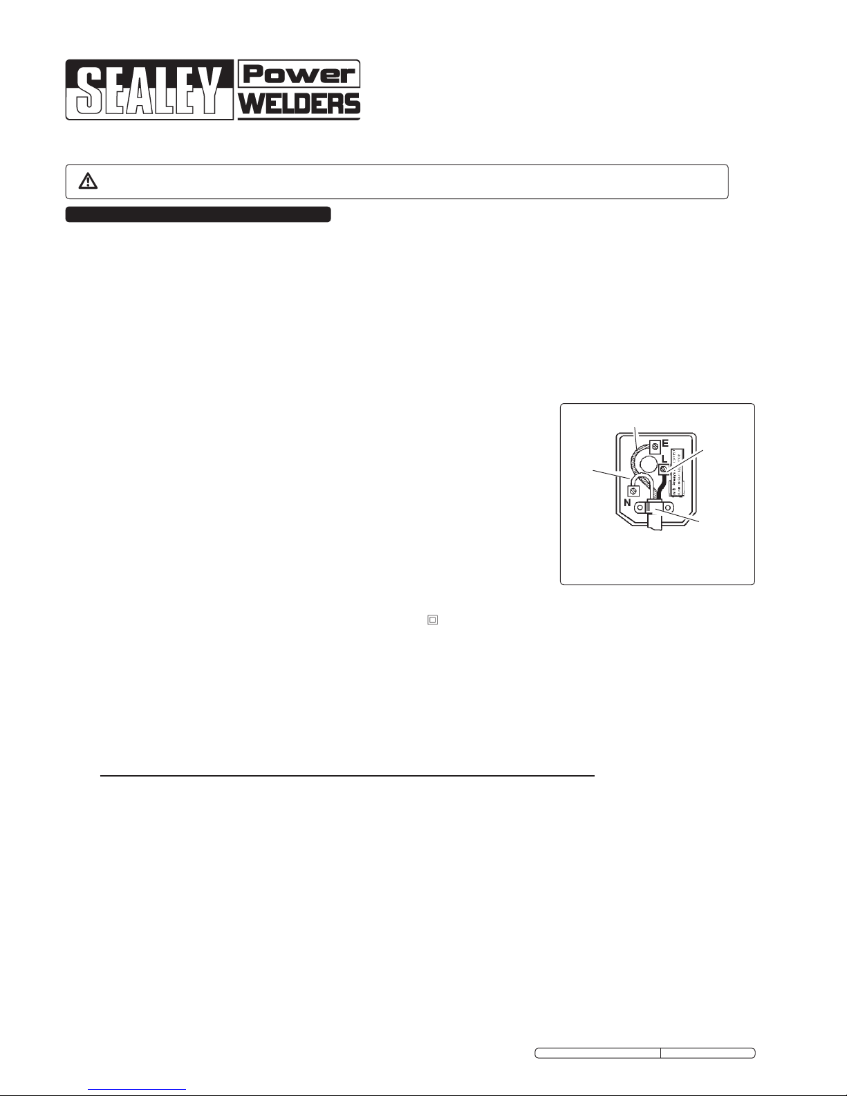
Fit a new plug according to the following instructions (UK only).
a) Connect the GREEN/YELLOW earth wire to the earth terminal ‘E’.
b) Connect the BROWN live wire to the live terminal ‘L’.
c) Connect the BLUE neutral wire to the neutral terminal ‘N’.
d) After wiring, check that there are no bare wires, that all wires have been correctly connected, that the cable outer insulation
extends beyond the cable restraint and that the restraint is tight.
Double insulated products, which are always marked with this symbol , are fitted with live (brown) and neutral (blue) wires only.
To rewire, connect the wires as indicated above - DO NOT connect either wire to the earth terminal.
1.1.10. Products which require more than 13 amps are supplied without a plug. In this case you must contact a qualified electrician to ensure
that a suitably rated supply is available. We recommend that you discuss the installation of an industrial round pin plug and socket with
your electrician.
1.1.11. If an extension reel is used it should be fully unwound before connection. A reel with an RCD fitted is preferred since any appliance
plugged into it will be protected. The cable core section is important and should be at least 1.5mm², but to be absolutely sure that the
capacity of the reel is suitable for this product and for others which may be used in the other output sockets, we recommend the use of
2.5mm² section cable.
WARNING! Be very cautious if using a diesel generator. The generator must be stable with regard to frequency (H3), voltage
and wave form. The output must be higher than the power (kVA) of the inverter. The diesel generator must also be self
regulating. If any A.M. feature is not respected the working of the regulation card may be affected.
Use of a generator without a regulator may be dangerous and will invalidate your inverter warranty.
RECOMMENDED FUSE RATING
13AMP
Blue
Neutral
Wire
Yellow & Green
Earth Wire
Cable
Restraint
Brown
Live
Wire
1.2. GENERAL SAFETY
DANGER! Unplug the inverter from the mains power supply before connecting or disconnect cables or performing maintenance or
service. Direct contact with the inverter circuit is dangerous.
Keep the inverter and cables in good working order and condition. Take immediate action to repair or replace damaged parts.
Use genuine parts and accessories only. Unapproved parts may be dangerous and will invalidate the warranty.
Keep the inverter clean for best and safest performance.
Locate the inverter in a suitable work area. Ensure that the area has adequate ventilation as welding fumes are harmful.
WARNING! Cable connectors must be turned fully into the quick plugs to ensure a good electrical contact. Loose connections will
cause overheating, rapid deterioration and loss in efficiency.
Ensure that there is no obstruction to the flow of clean, cool air and ensure that there are no conductive dusts, corrosive vapours or humidity
which could enter the inverter and cause serious damage.
Keep the work area clean and tidy and free from unrelated materials. Also ensure that the work area has adequate lighting.
WARNING: Use welding head shield to protect eyes and avoid exposing skin to ultraviolet rays given off by electric arc. Wear safety
welding gauntlets.
Remove ill fitting clothing, remove ties, watches, rings and other loose jewellery and contain long hair.
Ensure that the workpiece is correctly secured before operating the inverter.
Avoid unintentional contact with workpiece. Accidental or uncontrolled arcing on the electrode holder may be dangerous.
Protect cables from heat and sharp or abrasive items.
Keep unauthorised persons away from the work area. Any persons working within the area must adorn the same protective items.
Stand correctly keeping a good footing and balance, ensure that the floor is not slippery and wear non-slip shoes.
Original Language Version
MW131, MW151, MW151PLUS Issue No.1 24/10/11
2.1. INTRODUCTION
Suitable for ARC welding or for TIG welding (optional) using scratch-start method. Automatic Arc-Force circuitry makes the unit suitable
for TIG welding with a wide variety of rods including rutile, basic and stainless from Ø1.6mm up to Ø3.2mm (MW131) and Ø4mm
(MW151 & MW151PLUS). Includes thermal cut-out and mains voltage LEDs. Fitted with Hot-Start system to counter electrode sticking
during scratch starting. Supplied in carry-case with 10mm² arc welding accessory kit (Model No. INVMMA1) for MW131 and 16mm² arc
welding accessory kit (Model No. INVMMA2) for MW151 and MW151PLUS. All models supplied with shoulder strap. Also suitable for TIG
welding with optional TIG accessory kit. MW151PLUS features surge protection, allowing unit to be powered by a generator. Minimum
generator output of 6kW required.
2.2. DESCRIPTION
These welding machines are a power source for ARC welding, made specifically for direct current (DC). The specific characteristics of
the “INVERTER” system provide high speed and precise regulation, ensuring a high quality result for all stick electrode welding.
The “INVERTER” system, regulated at the input of the primary mains, also allows for a drastic reduction in the volumes of both the
transformer and the reactance. This reduction in volume and weight enhances the mobility of the machines. The units have power
modules which have been developed on a special printed circuit designed to maximise reliability and reduce maintenance.
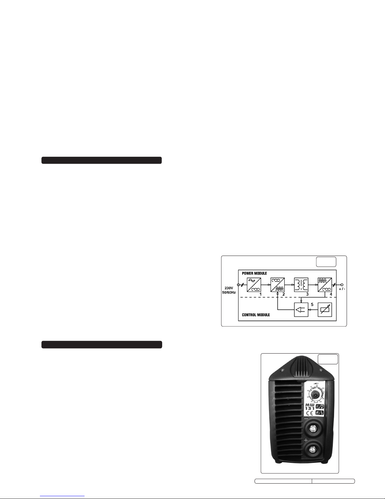
2.3. CIRCUIT SYSTEM DESCRIPTION Refer to fig. 1.
2.3.1. Mains input (single phase), rectifier unit and condenser.
2.3.2. Transistors and drivers switching bridge (IGBT). Turns the mains rectified
voltage into high frequency alternating voltage and permits power regulation
according to the current/voltage of the weld.
2.3.3. High frequency transformer: The primary windings are fed by the voltage
converted by Block 2. It has the function of adapting voltage and current to
the values required by the ARC welding procedure and, simultaneously,
isolates the welding circuit form the mains.
2.3.4. Secondary rectifier bridge with inductance. Changes the alternating current
supplied by the secondary windings into direct current.
2.3.5. Electronic and regulation board: Instantly checks the value of the welding
current against that selected by the user. It modulates the commands of the
IGBT drivers, which control regulation. The control board also determines the
dynamic response of the current transient during the phases of electrode
fusion (instant short circuit), and is responsible for the safety system.
2. DESCRIPTION
3. SPECIFICATION
3.1. SPECIFICATION
Model No. ................................MW131 .................................... MW151 ....................................MW151PLUS
Peak Power: ............................130A ........................................ 150A .........................................150A
Output: ..................................... 10 - 130A ................................. 10 - 150A .................................10 - 150A
Duty Cycle: ..............................30% @ 130A ........................... 25% @ 140A ............................25% @ 140A
Electrode Capacity: .................Ø1.6 - 3.2mm .......................... Ø1.6 - 4.0mm ...........................Ø1.6 - 4.0mm
Max Absorbed Power: .............3.9kW ...................................... 4.2kW .......................................4.2kW
Mains Voltage: ......................... 230V - 1PH ............................. 230V - 1PH ..............................230V - 1PH
Insulation Class: ......................F .............................................. F ...............................................F
Protection: ...............................IP21 ......................................... IP21 .........................................IP21
Weight: ....................................4.1kg ....................................... 4.1kg ........................................4.1kg
TIG Accessory Kit: ................... INVTIG1 ..................................INVTIG2 ...................................INVTIG2
fig.1
fig.2
Operators must receive adequate training before using the inverter.
WARNING: When unit is switched off the short-circuit light will come on for 10-15 seconds whilst capacitor discharges. DO NOT open unit until
light goes out.
DO NOT operate the inverter if it or the cables are damaged.
DO NOT use welding cables over 10m in length.
DO NOT attempt to fit any unapproved electrode holder, components, or parts to the inverter unit.
DO NOT connect the return cable to any metallic structure which is not part of the workpiece. This will jeopardise weld quality and may
be dangerous. Exception: Metallic work bench, but connect as near to weld as possible.
DO NOT hit the electrode on the workpiece, this may damage the electrode and make strike-up difficult.
DO NOT get inverter wet or use in damp or wet locations or areas where there is condensation.
DO NOT weld without a welding safety head shield.
DANGER! DO NOT weld near flammable materials - solids, liquids, or gases.
DO NOT weld containers or pipes which have held flammable materials - gases, liquids or solids. Avoid operating on materials cleaned
with chlorinated solvents or near such solvents.
DO NOT pull the inverter by the cables, or the electrode holder.
DO NOT bend, strain or stand on cables.
DO NOT place cables where they will endanger others. Long lengths of slack must be gathered and neatly coiled.
DO NOT touch the workpiece close to the weld as it will be very hot. Allow to cool.
DO NOT touch the torch immediately after use. Allow the electrode holder to cool.
DO NOT operate the inverter whilst tired or under the influence of drugs, alcohol or intoxicating medication.
When not in use, store the inverter in a safe, dry, childproof area.
MW131, MW151, MW151PLUS Issue No.1 24/10/11
Original Language Version
MW131
 Loading...