

Page 1

INSTRUCTIONS FOR
IMPORTANT: PLEASE READ THESE INSTRUCTIONS CAREFULLY. NOTE THE SAFE OPERATIONAL REQUIREMENTS, WARNINGS & CAUTIONS. USE
THE PRODUCT CORRECTLY AND WITH CARE FOR THE PURPOSE FOR WHICH IT IS INTENDED. FAILURE TO DO SO MAY CAUSE DAMAGE AND/OR
PERSONAL INJURY AND WILL INVALIDATE THE WARRANTY. KEEP THESE INSTRUCTIONS SAFE FOR FUTURE USE.
MINI TRACTOR/QUAD/MOTORCYCLE LIFT
680KG CAPACITY AIR/HYDRAULIC
MODEL NO: MT680.V4
Thank you for purchasing a Sealey product. Manufactured to a high standard, this product will, if used according to these instructions,
and properly maintained, give you years of trouble free performance.
Refer to
instruction
manual
1. SAFETY
9 Disconnect lift from air supply before changing parts, servicing or performing any maintenance.
WARNING! Ensure correct air pressure is maintained and not exceeded. Recommended pressure 120-200psi. Required air flow 9.5cfm.
9 Keep air hose away from heat, oil and sharp edges. Check air hose for wear before each use, and ensure that all connections are
secure.
9 Ensure lift is kept clean and in good working order. Immediately repair or replace damaged parts.
9 Use recommended parts only. Incorrect parts may be dangerous and will invalidate the warranty.
9 Use a qualified person to lubricate and maintain the lift. DO NOT use brake fluid to top up system. Use Sealey hydraulic oil only.
99 9 Locate lift in a suitable, well lit work area. Keep area clean and tidy and free from unrelated materials.
9 Use lift on level and solid ground, preferably concrete. Avoid tarmacadam since lift may sink in.
9 Ensure all non-essential persons keep a safe distance.
9 Always keep your hands and feet away from moving parts. DO NOT reach under the lift.
98 99 DO NOT operate the lift if parts are missing or damaged.
98 99 DO NOT adjust the safety overload valve.
9 Keep the lift clean for best and safest performance.
9 The maximum load is 680Kg. DO NOT exceed this rated capacity.
9 Use this lift for lifting purpose only. DO NOT use it for any other purpose it is not designed to perform.
9 Keep children and unauthorised persons away from the work area.
9 Remove ill fitting clothing. Remove ties, watches, rings and other loose jewellery, and contain long hair.
9 Keep proper balance and footing, DO NOT overreach and wear non-slip footwear.
9 Ensure the vehicle is adequately secured to the lifting platform with appropriate straps.
9 When the platform is being raised, ensure the safety handle is moved to the right hand side of its detent, to engage the safety plate,
(see 6.5.1).
8 Before lowering lift ensure that there are no obstructions underneath and that all persons are standing clear.99
8 DO NOT use the lift if damaged, any suspect parts are noted or it has been subjected to a shock load.
8 DO NOT operate the lift when you are tired or under the influence of alcohol, drugs or any intoxicating medication.
8 DO NOT allow untrained persons to operate the lift.
8 DO NOT make any modifications to the lift.
8 DO NOT get the lift wet.
98 99 DO NOT pull the hose from the air supply, and DO NOT direct air from the air hose at yourself or others.
99 9 When not in use disconnect lift from the air supply, and store in the down position in a safe, dry, childproof area.
WARNING: The warnings, cautions and instructions discussed in this instruction manual cannot cover all possible conditions
and situations that may occur. It must be understood that common sense and caution are factors which cannot be built into this
product, but must be applied by the operator.
2. iINTRODUCTION
All steel construction with heavy duty hydraulic ram and air pump. Integral hydraulic pump and air motor assembly. Supplied with separate foot
operated hydraulic pump and reservoir unit. Features two additional side platforms for extra width. Ramp and platform made with chequer plate
surface to ease loading and positioning of mini tractor/quad. Supplied with motorcycle front wheel locking attachment, securing vehicle to provide
easy access maintenance access. Fitted with safety lock to prevent accidental lowering. Suitable for use with centre stand motorcycles or with
paddock stand.
© Jack Sealey Limited
Original Language Version
MT680.V4 | Issue 1 - 21/04/16
Page 2
3. SPECIFICATION
Model no: ...............................................................MT680.V4
Capacity: ...................................................................... 680kg
Min. height: ................................................................ 190mm
Max. height: ............................................................... 790mm
Standard width: .......................................................... 710mm
Max. width: ............................................................... 1220mm
Length: ..................................................................... 2000mm
g.1
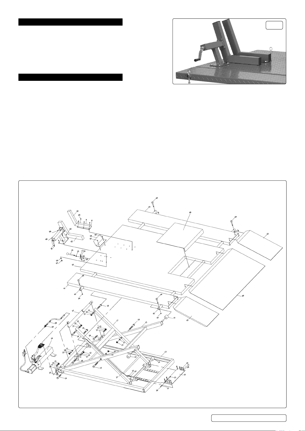
4. ASSEMBLY
Refer to parts diagram below.
4.1. Lay the sliding plate (8) onto the platform (1).
4.2. Connect the oil hose coupler (29) to the port on the hydraulic pump (20).
4.3. Connect air hose into the end of the air/manual pump (20).
4.4. Attach the leading plate (9) to the end of the platform (1).
4.5. Insert safety handle (36) through detent on rear end of lift and screw into thread on the bracket on the end of the safety wire (31).
4.6. Tighten lock nut (35).
4.7. Fit motorcycle wheel clamp (also see g.1)
4.8. Fit crank handle assembly (40) to platform (1) through pre-drilled holes, use bolt (5) washer (38) and nut (7).
4.8.1. Fit moveable vice jaw (2) to crank handle assembly (40), use bolt (6).
4.8.2. Fitxedvicejaw(3)toplatform(1),usebolt(5).
4.8.3. Fit stop plate (4) to platform (1), use bolt (5).
4.9. Fit side extensions
4.9.1. Pass connecting bars (42) through front and rear holes in platform (1). Slide on side extensions (41).
4.9.2. Secure at each end of the connecting bars (42) with position pins (44). Fit pin through hole on the end of the connecting bar and
secure with lock nut (34).
4.9.3. Fit side extension ramp extensions (43).
© Jack Sealey Limited
Original Language Version
MT680.V4 | Issue 1 - 21/04/16
Page 3

5. AIR SUPPLY
5.1. You will require an air pressure of minimum 120psi, maximum 200psi to get the best performance from this lift.
WARNING! Ensure the air supply does not exceed 200psi while operating the lift. Too high an air pressure and unclean air will shorten
the product’s life due to excessive wear, and may be dangerous, causing possible damage and/or personal injury.
5.2. Drain the air tank daily. Water in the air line will damage the lift.
5.3. Clean the air inlet filter screen weekly.
5.4. Keep the air hose between the compressor and the lift as short as possible, and install an air filter and oiler, (fig 2).
5.5. Line pressure should be increased to compensate for unusually long air hoses (over 8 metres). The minimum hose
diameter should be 1/4” I.D. and fittings must have the same inside dimensions.
5.6. Keep hose away from heat, oil and sharp edges. Check hoses for wear, and make certain that all connections are secure.
g.2
6. PREPARATION FOR USE
VENT IN TRANSIT
POSITION
OPEN VENT
BEFORE USE
Fig.3
Fig.3A
VENT VALVE
LOCATION
g.3
6.1. Before use
6.1.1. MT680 has a vent valve, see Fig.3A. This is closed for transit only. Before use the valve must be lifted or the pump will
not function properly.
6.1.2.
Let the hydraulic pump stand for one hour, to allow the oil to settle, before purging the system.
NOTE: Failure to allow sufficient time for the oil to settle could result in air remaining in the oil. Should the pump fail to purge completely
at the first attempt, a second purge will be required.
6.1.3. Purge the hydraulic system by depressing the release foot pedal and pumping the lift foot pedal fifteen to twenty times.
6.1.4.
Test the lift unladen by moving the safety handle to the right and raising the lift to full height.
6.1.5. Safety handle operation
6.1.5.1. To raise. Before raising the lift the safety handle must be moved to the right hand side of the detent, see fig.4 to prevent accidental
lowering.
6.1.5.2. To lower. Raise the lift by pumping the foot pedal several times (or by air), to let the safety plate free from its locked position, then move
the safety handle to the left and lock it in its detent, see fig.5
6.1.5.3. Lower the lift by depressing the release foot pedal slowly, to control the rate of descent.
g.4
6.2. Operation (Refer to the Parts Diagram)
9 99 WARNING! Ensure that you read, understand and apply the Section 1 Safety Instructions.
9
99 WARNING! DO NOT overload the Vehicle lift. The maximum load is 680kg.
6.2.1.
Position the lift in a suitable location, preferably on a concrete surface.
6.2.2.
Turn the adjustable screws (24) down to ensure that lift is level and stable on the surface.
6.2.3.
Wheel the vehicle up the leading plate/s and on to the lift platform.
© Jack Sealey Limited
Original Language Version
g.5
MT680.V4 | Issue 1 - 21/04/16
Page 4

9 99 WARNING! The vehicle must be fully supported by the lift platform prior to lifting. DO NOT put the rear wheel of the vehicle on the leading
plate (9) and DO NOT use the leading plate to support the weight of the vehicle when lifting. The leading plate (9) is only used to assist
the operator in wheeling the vehicle on the platform when the lift is at its lowest position.
6.2.4. Secure the vehicle to the lift platform.
6.2.5. When working on a motorcycle, wheel the bike in to the wheel clamp at the front of the lift, tighten the clamp to hold the bike in place.
6.2.6. Press on the air valve to raise the lift. The air valve can be locked in the on position, see figs.6 and 7.
g.6
NOTE: Ensure the safety handle is to the right and the lock plate assembly (10) is locked in a corresponding pair of safety latches to
prevent accidental lowering.
6.2.7. When work is completed, remove all tools from underneath the lift before lowering.
6.2.8. Move the safety handle to the left hand side (into the detent lock) and lower the lift, refer to 6.1.5.2., by slowly depressing the release
foot pedal to gently lower the vehicle. Move the safety handle back to the right hand side ready for the next lifting operation.
NOTE: Lower the vehicle slowly, in a controlled fashion. Never allow the vehicle to lower rapidly.
6.2.9. When the lift is fully lowered, remove the vehicle from the lift.
g.7
7. MAINTENANCE
7.1. Regularly check oil level via filler hole. With piston fully down remove filler plug, oil should be level with bottom of filler hole. Top-up as
necessary. Use a good quality jack oil such as Sealey Hydraulic Jack Oil. Do not use brake fluid.
7.2. Ensure no dirt enters hydraulic system when filling or removing/replacing components.
7.3. Lubricate the air motor with a good quality jack oil such as Sealey Hydraulic Jack Oil, once or twice a month. Add the oil through the air
valve whilst holding down the lever.
7.4. Keep the lift clean and wipe off any oil or grease. Lubricate all moving parts.
7.5. Before each use check all parts. If any part of the lift is damaged or suspect, remove the lift from service and take necessary action to
repair.
8. TROUBLESHOOTING
1. Release valve not fully closed.
Lift will not lift load.
Lift will not hold load. 1. Release valve not fully closed. 1. Close valve firmly.
Lift will not lift smoothly
or to full height.
Lift will not lower completely. 1. Release valve not sufficiently open. 1. Slowly open valve further.
NOTE: It is our policy to continually improve products and as such we reserve the right to alter data, specications and component parts without prior notice.
IMPORTANT: No liability is accepted for incorrect use of this product.
WARRANTY: Guarantee is 12 months from purchase date, proof of which will be required for any claim.
2. Oil level low.
3. Air supply low.
1. Oil level low.
2. Air in hydraulic system.
Sole UK Distributor, Sealey Group.
Kempson Way, Suffolk Business Park,
Bury St. Edmunds, Suffolk.
IP32 7AR
1. Close valve firmly.
2. Top-up to correct level.
3. Min. requirement 120psi.
1. Top-up to correct level.
2. Bleed system.
01284 757500
01284 703534
www.sealey.co.uk
Web
sales@sealey.co.uk
© Jack Sealey Limited
Original Language Version
MT680.V4 | Issue 1 - 21/04/16
 Loading...