

INSTRUCTIONS FOR:
ABRASIVE DISC CUT-OFF SAW
Models:
MG214/230V.V2
MG214/110V.V2
Thank you for purchasing a Sealey product. Manufactured to a high
standard this product will, if used according to these instructions
and properly maintained, give you years of trouble free performance.
1. SAFETY INSTRUCTIONS
IMPORTANT: PLEASE READ THESE INSTRUCTIONS CAREFULLY. NOTE THE SAFE OPERATIONAL REQUIREMENTS, WARNINGS AND
CAUTIONS. USE THIS PRODUCT CORRECTLY AND WITH CARE FOR THE PURPOSE FOR WHICH IT IS INTENDED. FAILURE TO DO SO MAY
CAUSE DAMAGE AND/OR PERSONAL INJURYAND WILL INVALIDATE THE WARRANTY. PLEASE KEEP INSTRUCTIONS SAFE FOR FUTURE USE.
1.2. GENERAL SAFETY
! WARNING! Disconnect the saw from the mains power, and ensure that the cutting disc is at a complete standstill before attempting to
change accessories, service or perform any maintenance.
" Maintain the saw in good condition (use an authorised service agent).
" Replace or repair damaged parts. Use recommended parts only. Unauthorised parts may be dangerous and will invalidate the warranty.
" Locate the saw in a suitable work area. Ensure that the surface is flat and firm. Keep the area clean and tidy and free from unrelated
materials, and ensure that there is adequate lighting.
" Keep the saw clean for best and safest performance and check moving parts alignment regularly.
! WARNING! Before each use check that the cutting disc is secure and that it is not worn or damaged.
NOTE: Only persons qualified under the “Abrasive Wheels Regulations” holding a current grinding wheel certificate may change discs (wheels).
" Ensure that replacement discs are not damaged in any way - cracks, deformations or splinters etc. Also check the mounting flanges to
ensure that they are not deformed, burred or chipped. Damaged flanges must not be used as they may cause uneven pressure on the disc
which may cause the disc to break. DO NOT over tighten a disc and never tamper with a disc in order to adapt it to a different size holder.
" Always use a disc suitable for the material being cut. Ensure that the cutting disc’s specified maximum speed is equal to, or higher than, that
indicated on the machine data plate. Once mounted on the grinder, test the disc before use by facing the grinder in a safe direction (point
disc away from yourself, others and vulnerable items) and running it for a short time.
! WARNING! Keep guard and holding screws in place, tight and in good working order. Check regularly for damaged parts.
A guard or any other part that is damaged must be repaired or replaced before next use. The safety guard is a mandatory fitting when the
saw is used on premises covered by the Health & Safety at Work Act.
1.1. ELECTRICAL SAFETY
! WARNING! It is the responsibility of the owner and the operator to read, understand and comply with the following:
You must check all electrical products, before use, to ensure that they are safe. You must inspect power cables, plugs, sockets and any other
connectors for wear or damage. You must ensure that the risk of electric shock is minimised by the installation of appropriate safety devices.
A Residual Current Circuit Breaker (RCCB) should be incorporated in the main distribution board. We also recommend that a Residual Current
Device (RCD) is used. It is particularly important to use an RCD with portable products that are plugged into a supply which is not protected
by an RCCB. If in any doubt consult a qualified electrician. You may obtain a Residual Current Device by contacting your Sealey dealer.
You must also read and understand the following instructions concerning electrical safety.
1.1.1. The Electricity at Work Act 1989 requires that all portable electrical appliances, if used on
business premises, are tested by a qualified electrician, using a Portable Appliance Tester
(PAT), at least once a year.
1.1.2. The Health & Safety at Work Act 1974 makes owners of electrical appliances responsible
for the safe condition of those appliances and the safety of the appliance operators. If in
any doubt about electrical safety, contact a qualified electrician.
1.1.3. Ensure that the insulation on all cables and on the appliance is safe before connecting it to
the power supply. See 1.1.1. and 1.1.2. and use a Portable Appliance Tester.
1.1.4. Ensure that cables are always protected against short circuit and overload.
1.1.5. Regularly inspect power supply cables and plugs for wear or damage and check all
connections to ensure that none is loose.
1.1.6. Important: Ensure that the voltage marked on the appliance matches the power supply
to be used and that the plug is fitted with the correct fuse - see fuse rating, fig. 1.
1.1.7. DO NOT pull or carry the appliance by the power cable.
1.1.8. DO NOT pull the plug from the socket by the cable.
1.1.9. DO NOT use worn or damaged cables, plugs or connectors. Immediately have any faulty
item repaired or replaced by a qualified electrician.
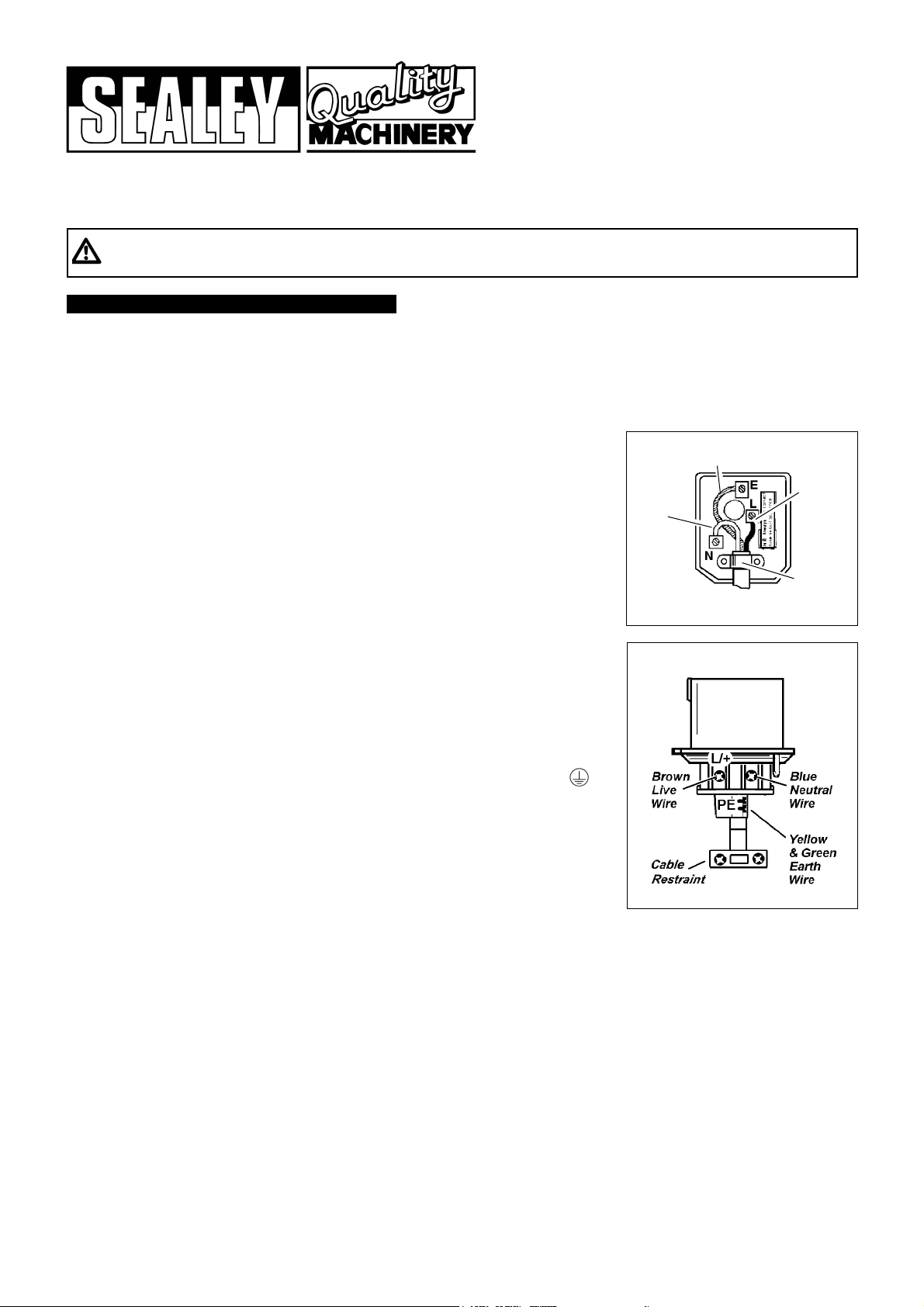
Fit a new plug according to the following instructions (UK only):
MG214/230V - fig. 1
MG214/110V - fig. 2
a) Connect the GREEN/YELLOW earth wire to the earth terminal ‘E’ or .
b) Connect the BROWN live wire to the live terminal ‘L’.
c) Connect the BLUE neutral wire to the neutral terminal ‘N’.
d) After wiring, check that there are no bare wires, that all wires have been correctly
connected, that the cable outer insulation extends beyond the cable restraint and
that the restraint is tight.
1.1.10. If an extension reel is used it should be fully unwound before connection. A reel with an
RCD fitted is preferred since any appliance plugged into it will be protected. The cable core
section is important and should be at least 1.5mm
2
, but to be absolutely sure that the
capacity of the reel is suitable for this product and for others which may be used in the other
output sockets, we recommend the use of 2.5mm
2
section cable.
FUSE RATING 13 AMP
Blue
Neutral
Wire
Yellow & Green
Earth Wire
Cable
Restraint
Brown
Live
Wire
fig. 1
fig. 2
MG214/230V.V2 & MG214/110V.V2 - 2 - 060807
! WARNING! Before cutting ensure that you wear approved safety goggles, ear defenders, appropriate dust mask if cutting
generates dust, and safety gloves. All safety instructions in Section 1 must be followed.
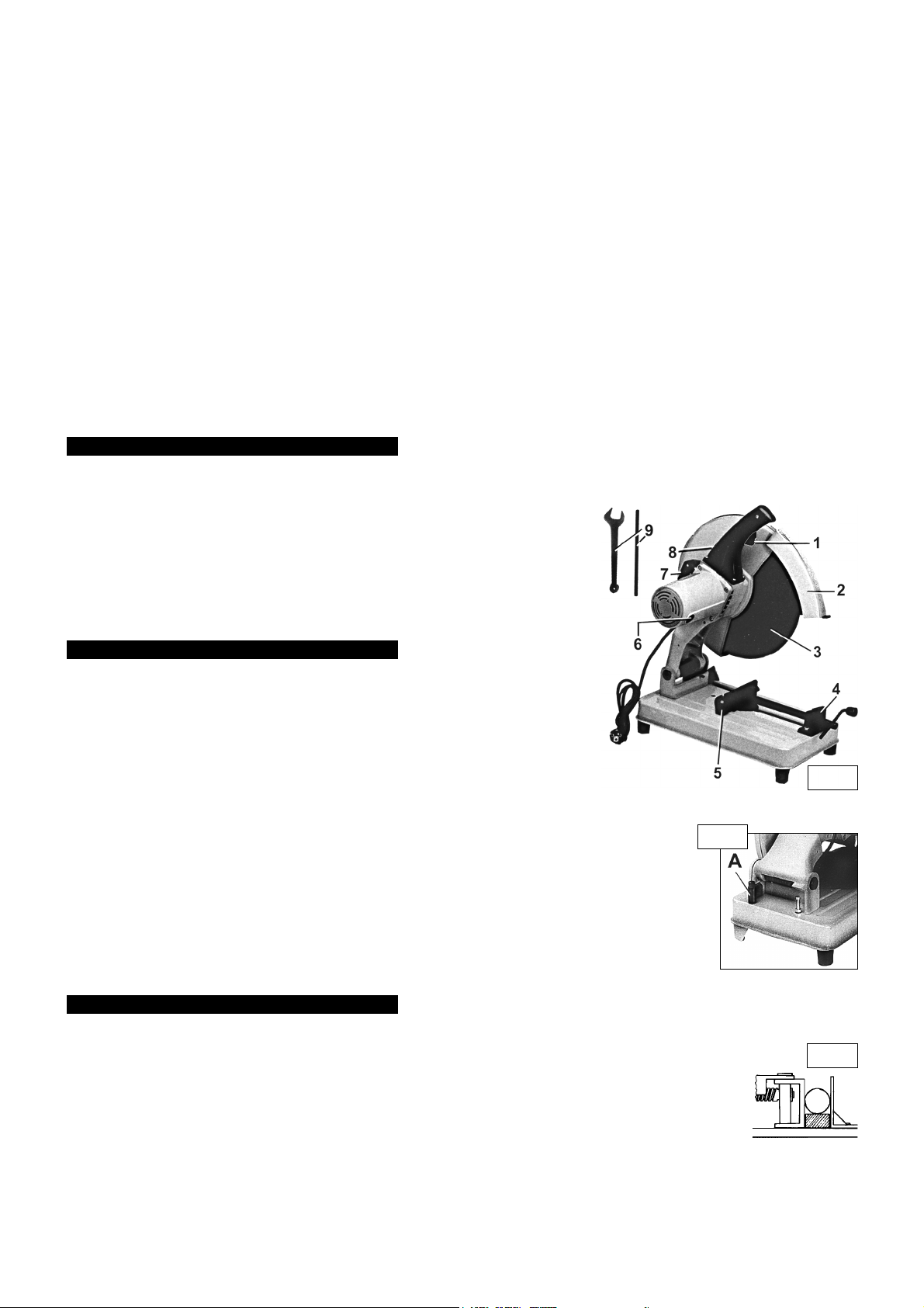
4.1. Securing workpiece
4.1.1. Ensure that the saw is unplugged from the power supply and then secure the workpiece in the base vice (fig. 1.5).
We recommend that you place a block of wood (slightly narrower than the workpiece) in the vice below the item to
be cut to act as a support (fig. 3).
4.1.2. For additional cutting capacity re-locate the vice back stop (fig. 1.5) in the rear vice holes and fully secure.
4.1.3. When cutting long workpieces use additional supports along the length.
4.2. On/Off switch
Plug the saw into the power supply and start the saw by depressing the power switch located on the handgrip (fig. 1.1). Release the
switch to stop the saw.
4.3. Overload switch
If the saw becomes overloaded the overload switch (fig. 1.8) will cut the power to the machine. To reset, press the switch down, first
ensuring that the On/Off switch is in the Off position.
The MG214 is a general purpose abrasive saw suitable for site use. Supplied with abrasive disc for metal cutting but will cut concrete with
the correct disc fitted. Fully guarded disc and integral work vice are included.
2. APPLICATION & SPECIFICATIONS
Size of disc . . . . . . . . . . 355 x 3 x 25.4mm
Disc Part No. . . . . . . . . . . . . . . . PTC/355C
Cutting capacity . . . . . . . Ø60mm round bar
Ø115mm pipe
Maximum vice opening . . . . . . . . . . 190mm
Motor . . . . . . . . . . . . . . . . . . . 230V 2300W
110V 2000W
3. CONTENTS & ASSEMBLY
3.1. Open the carton, remove any packing, and carefully lift the saw out by holding the hand grip.
Ensure that you maintain the correct posture for lifting.
3.2. To clamp the motor head in the (down) transport position turn the locking plate inward (fig. 2.A).
3.3. Position the saw on a flat, stable work bench, strong enough to support the saw and any workpiece.
3.4. Remove any packing from the vice.
3.5. Before using the saw, check that disc is perpendicular to the base of machine and that all parts are
in good order and correctly secured.
Specifications:
fig. 1
fig. 2
fig. 3
4. OPERATING INSTRUCTIONS
Description:
1 On/Off switch
2 Disc safety guard
3 Cutting disc
4 Vice
5 Vice back stop & angle guide
6 Carbon brush cap
7 Carry handle
8 Overload switch
9 Disc removing tools
" Remove adjusting keys and wrenches from the machine and its vicinity before turning it on.
! WARNING! Wear approved safety eye protection, ear defenders, gauntlets and, if dust is generated, respiratory protection.
" Remove ill fitting clothing. Remove ties, watches, rings and other loose jewellery and contain long hair.
" Keep hands and body clear of the worktable when operating the saw, and DO NOT position your body in line with the abrasive wheel.
" Maintain correct balance and footing. Ensure the floor is not slippery and wear non-slip shoes.
" Keep children and unauthorised persons away from the work area.
" Avoid subjecting disc to excessive strain, always ease disc down against workpiece (a harsh downward impact may break the disc). Do not
apply undue force on the handle in order to cut workpiece. Maintain a controlled cutting speed through the workpiece.
! WARNING! DO NOT switch on the saw whilst the disc is in contact with the workpiece. Bring the rotating disc to the workpiece.
Avoid unintentional starting of the saw.
$ DO NOT hold the workpiece by hand. Use base vice to secure the workpiece.
$ DO NOT use the saw for a task it is not designed to perform.
$ DO NOT allow untrained persons to operate the saw.
$ DO NOT get the saw wet, or use in damp or wet locations or areas where there is condensation.
! WARNING! DO NOT use the saw where there are flammable liquids, solids or gases such as paint solvents and including waste wiping rags etc.
$ DO NOT operate the saw if any parts are missing or damaged as this may cause failure and/or personal injury.
$ DO NOT remove the safety guard whilst the saw is in use.
$ DO NOT attempt to remove a workpiece until the disc has stopped rotating.
$ DO NOT touch the workpiece close to the cut as it will be very hot. Allow to cool. The cut edge of the workpiece will also be very sharp.
$ DO NOT leave the saw operating unattended.
$ DO NOT operate the saw when you are tired or under the influence of alcohol, drugs or intoxicating medication.
" When not in use switch off the saw and remove the plug from the power supply.
" To move the saw, lock the machine head with the locking plate and lift by the handle.
IMPORTANT: Abrasive disc MUST
Only be fitted by a qualified person. See Sections 1.2. & 5.
No-load speed . . . . . . . . . . . . . . . 3900rpm
Mitre angles . . . . . . . . . . . . . . . . . . 0 - ±45
O
Weight . . . . . . . . . . . . . . . . . . . . . . . .23kg
Sound pressure level . . . . . . . . . 112dB(A)
Sound power level . . . . . . . . . . . .125dB(A)
Unpack the product and check the contents.
Ensure that there is no damage. If any problem is noted, contact your supplier immediately.
MG214/230V.V2 & MG214/110V.V2 - 2 - 060807

Declaration of Conformity We, the sole importer into the UK, declare that the products listed here
are in conformity with the following standards and directives.
The construction files for these products are held by the Manufacturer and may be inspected, by a national authority,
upon request to Jack Sealey Ltd.
For Jack Sealey Ltd. Sole importer into the UK of Sealey Quality Machinery.
Abrasive Disc Cut-Off Saws
Models MG214/230V.V2 & MG214/110V.V2
73/23/EEC Low Voltage Directive
89/336/EEC EMC Directive
98/37/EC Machinery Directive
93/68/EEC CE Marking Directive
2002/95/EC RoHS Directive
2002/96/EC WEEE Directive
Signed by Mark Sweetman
6th August 2007
4.4. Operation
! WARNING! DO NOT switch on the saw whilst the disc is in contact with the workpiece. Bring the rotating disc to the workpiece.
4.4.1. The cutting disc must be running at maximum speed before attempting to lower the cutting edge onto the workpiece.
4.4.2. Lower the cutting disc slowly and smoothly down toward the workpiece (avoid jerky movements).
4.4.3. Avoid subjecting the disc to excessive strain. Always ease the disc down against workpiece (a harsh downward impact may cause
disc failure) and do not apply undue force on the handle when cutting the workpiece. Maintain a controlled cutting speed.
4.5. Completing the cut
4.5.1. When cutting is complete, fully raise the cutting disc and release the On/Off switch.
4.5.2. Wait until the disc has stopped rotating before attempting to remove the workpiece.
4.6. Mitre cutting
To cut the workpiece at an angle the base of the saw must be adjusted.
4.6.1. To make an angled cut, loosen the vice back plate retaining bolts (fig. 4.A) and turn the turntable to
the required angle, reading the graduated scale around the perimeter of the vice back plate.
4.6.2. Re-tighten the retaining bolts and make the cut.
5. CHANGING CUTTING DISC
6. MAINTENANCE
7. DECLARATION OF CONFORMITY
! WARNING! Ensure that the saw is unplugged from the power supply before attempting
any maintenance.
6.1. Regularly clean the dust which accumulates inside the protective guard and on the external parts.
6.2. Periodically clean and oil the vice screw.
6.3. Change the abrasive disc when it is worn and does not operate efficiently.
6.4. To change the motor brushes removed the brush caps with a screwdriver (fig. 7). Replace the
carbon brushes and re-install the brush caps.
Sealey Group,
Bury St. Edmunds, Suffolk.
MG214/230V.V2 & MG214/110V.V2 - 2 - 060807
fig. 4
A
NOTE: It is our policy to continually improve products and as such we reserve the right to alter data, specifications and component parts without prior notice.
IMPORTANT: No liability is accepted for incorrect use of this equipment.
WARRANTY: Guarantee is 12 months from purchase date, proof of which will be required for any claim.
INFORMATION: For a copy of our catalogue and latest promotions call us on 01284 757525 and leave your full name, address and postcode.
%
DANGER! The use of damaged discs is dangerous and may cause injury.
! WARNING! Ensure that the saw is unplugged from the power supply before attempting to
change the cutting disc.
Before using a cutting disc ensure that there are no fissures or cracks in it. Once mounted on the saw
test the disc before use by facing the saw in a safe direction (turned away from yourself, others and
vulnerable items) and running it for a short time.
IMPORTANT! Cutting discs used with this machine shall be of an adequate speed rating and
suitable for the task in hand. Only persons qualified under the “Abrasive Wheels Regulations” and holding a current grinding wheel
certificate are to change cutting discs.
01284 757500
sales@sealey.co.uk
www.sealey.co.uk
01284 703534
e-mail
Web
fig. 7
5.1. Removing disc
5.1.1. With the head in the up position rotate the disc guard until the handle engages with the slot
in the fixed guard (fig. 5.A).
5.1.2. Loosen the centre guard clamp screw (fig. 5.B) and swing the centre guard (fig. 5.D) down.
5.1.3. Place the holding tool in the spindle hole (hole is located on the motor side of the disc, see fig. 6).
5.1.4. Use the spanner to remove disc clamp bolt (fig. 5.C).
5.1.5. Carefully remove the disc and clamping parts.
5.1.6. Clean parts before re-assembly.
5.2. Fitting disc (fig. 6)
WARNING! Read Section 1 safety instructions to ensure disc fitting requirements are followed.
5.2.1. Fit the inner flange (2) checking to ensure that it seats correctly on the spindle (1).
Fit the disc and items 3,4 & 5 to the spindle.
5.2.2. Fit and tighten the locking bolt (6).
5.2.3. Before plugging the saw into the mains, move the disc guard back to the closed position so
that the disc is covered.
5.2.4. Check that the guard is working properly by raising and lowering the operating head.
fig. 6
fig. 5

PARTS LIST FOR:
ABRASIVE DISC CUT-OFF SAW
Models:
MG214/230V.V2 & MG214/110V.V2
Sealey Group,
Bury St. Edmunds, Suffolk.
01284 757500
sales@sealey.co.uk
www.sealey.co.uk
01284 703534
e-mail
Web
Item Part No. Description
1 MG214.V2-001 Screw
1A MG214.V2-001A Motor Assembly, 230V
1A MG214.V2-001B Motor Assembly, 110V
2 MG214.V2-002 Rear Cover
3 MG214.V2-003 Screw
4 MG214.V2-004 Motor Housing
5 MG214.V2-005 Brush Holder
6 MG214.V2-006 Carbon Brush
7 MG214.V2-007 Brush Cap
8 MG214.V2-008 Screw
9 B/6200ZZ Bearing
10 MG214.V2-010A Field Coil Asm, 230V
10 MG214.V2-010B Field Coil Asm, 110V
11 MG214.V2-011 Screw
12 MG214.V2-012 Plastic Ring
13 MG214.V2-013A Rotor Asm, 230V
13 MG214.V2-013B Rotor Asm, 110V
14 B/6002-2RS Bearing
16 MG214.V2-016 Strain Relief
19 MG214.V2-019 Screw
20 MG214.V2-020 Nut
21 MG214.V2-021 Arm
22 B/608ZZ Bearing
23 MG214.V2-023 C-ring
24 MG214.V2-024 Gear
25 MG214.V2-025 C-ring
26 B/6006ZZ Bearing
27 MG214.V2-027 Side Cover
28 MG214.V2-028 Screw
29 MG214.V2-029 Key
30 MG214.V2-030 Shaft
31 MG214.V2-031 Spring
32 MG214.V2-032 Safety Guard
Item Part No. Description
33 MG214.V2-033 C-ring
34 MG214.V2-034 Flange, Inner
35 MG214.V2-035 Abrasive Wheel
37 MG214.V2-037 Washer
38 MG214.V2-038 Hex. Head Screw
39 MG214.V2-039 Nut
40 MG214.V2-040 Wheel Cover
41 MG214.V2-041 Screw
42 MG214.V2-042 Side Cover
43 MG214.V2-043 Screw
44 MG214.V2-044 Washer
45 MG214.V2-045 Screw
46 MG214.V2-046 Screw
47 MG214.V2-047 Washer
48 MG214.V2-048 Screw
49 MG214.V2-049 Screw
50 MG214.V2-050 Crank, Left
51 MG214.V2-051 Crank, Right
52 MG214.V2-052 Wire Connector (230V only)
53 MG214.V2-053 EMC Filter (230V only)
54 MG214.V2-054 Overload Switch
55 MG214.V2-055 On/Off Switch
56 MG214.V2-056 Screw
57 MG214.V2-057 Quick Release Nut
58 MG214.V2-058 Pin
59 MG214.V2-059 Lead Screw Seat
60 MG214.V2-060 C-ring
61 MG214.V2-061 Handle
62 MG214.V2-062 Lead Screw
63 MG214.V2-063 C-ring
64 MG214.V2-064 Clamping Shaft
65 MG214.V2-065 Clamp (B)
66 MG214.V2-066 Washer
Item Part No. Description
67 MG214.V2-067 Lock Nut
68 MG214.V2-068 Flat Washer
69 MG214.V2-069 Pin
70 MG214.V2-070 Clamp (A)
71 MG214.V2-071 Screw
72 MG214.V2-072 Spring Washer
73 MG214.V2-073 Nut
74 MG214.V2-074 Screw
75 MG214.V2-075 Shaft
76 MG214.V2-076 Screw
77 MG214.V2-077 Screw
78 MG214.V2-078 Screw
79 MG214.V2-079 Spring Washer
80 MG214.V2-080 Screw
81 MG214.V2-081 Bracket Plate
82 MG214.V2-082 Torsion Spring
83 MG214.V2-083 Housing Seat
84 MG214.V2-084 Lever
85 MG214.V2-085 E-ring
86 MG214.V2-086 Screw
87 MG214.V2-087 Screw
88 MG214.V2-088 Rubber Pad
89 MG214.V2-089 Screw
90 MG214.V2-090 Base
91 MG214.V2-091 Crank, Left
92 MG214.V2-092 Crank, Right
94 MG214.V2-094 Spring Washer
95 MG214.V2-095 Screw
108 MG214.V2-108 Screw
109 MG214.V2-109 Protection Rubber
114 MG214.V2-114 Screw
115 MG214.V2-115 C-ring
116 MG214.V2-116 Screw
117 MG214.V2-117 Bearing Cover
118 MG214.V2-118 Protection Rubber (230V only)
119 MG214.V2-119 Screw (230V only)
121 MG214.V2-121 Soft Start (230V only)
122 MG214.V2-122 Protection Rubber
123 MG214.V2-123 Tapping Screw
124 MG214.V2-124 Nut
Issue: 1
Date Issued: 060303
 Loading...