

INSTRUCTIONS FOR:
HYDRAULIC MOTORCYCLE LIFT 450kg
MODEL No: MC450
Thank you for purchasing a Sealey product. Manufactured to a high standard this product will, if used according to these instructions and
properly maintained, give you years of trouble free performance.
IMPORTANT: PLEASE READ THESE INSTRUCTIONS CAREFULLY. NOTE THE SAFE OPERATIONAL REQUIREMENTS, WARNINGS AND CAUTIONS.
USE THE PRODUCT CORRECTLY AND WI TH CARE FOR THE PURPOSE FOR WHI CH IT IS INTENDED. FAILURE TO DO SO M AY CAUSE
DAMAGE AND/OR PERSONAL INJURY AND WILL INVALIDATE THE WARRANTY. PLEASE KEEP INSTRUCTIONS SAFE FOR FUTURE USE.
1. SAFETY INSTRUCTIONS
WARNING! Ensure the bike is adequately secured to the
lifting platform with appropriate straps before raising the load.
Maintain the lift in good condition (use an authorised service agent).
Replace or repair damaged parts. Use genuine parts only.
Unauthorised parts may be dangerous and will invalidate the
warranty.
Use a qualified person to lubricate and maintain the lift. DO NOT
use brake fluid to top up hydraulic unit.
Locate the lift in a suitable work area, keep area clean and tidy
and free from unrelated materials, and ensure that there is
adequate lighting. Also ensure that the floor is level and strong
enough (preferably concrete) to take the weight of the lift and the
bike. DO NOT operate the lift on tarmacadam, as the surface
may be unstable.
Keep the lift clean for best and safest performance.
The maximum bike weight is 450kg. DO NOT exceed this rated
capacity.
Remove ill fitting clothing. Remove ties, watches, rings and other
loose jewellery, and contain long hair.
Maintain correct balance and footing, do not over reach. Ensure
the floor is not slippery and wear non-slip shoes.
Before lifting check that there are no overhead obstructions.
When platform has been raised to the working height ensure the
locking bar is engaged to prevent accidental lowering.
Keep children and unauthorised persons away from the work area.
The lowering speed will vary according to the weight of the load
and the amount of pressure applied to the release pedal.
DO NOT attempt to ride a motorcycle up onto the lift
DO NOT use the lift for a task it is not designed to perform.
DO NOT operate the lift if damaged.
DO NOT exceed the rated capacity of the lift.
DO NOT operate the lift when you are tired or under the influence
of alcohol, drugs or intoxicating medication.
DO NOT allow untrained persons to operate the lift.
DO NOT make any modifications to the lift and DO NOT adjust or
tamper with the safety valve.
DO NOT sit or stand on the lift or hold onto it when it is being
raised or lowered.
DO NOT attempt to raise the lift using manual strength.
DO NOT put any body parts within the interior frame of the lift
whilst raising or lowering.
DO NOT use the ram alone to maintain a raised motorcycle.
ALWAYS engage the locking mechanism.
Before lowering the lift ensure that there are no obstructions
underneath and that all persons are standing clear.
Before storing in safe area, ensure all parts are clean and free of
grease and oil. Store lift in the lowest position.
2. SPECIFICATION
Capacity .................................................................................450kg
Overall Width/Length .................................................. 800/3140mm
Height Minimum/Maximum ........................................... 175/810mm
Net weight .............................................................................72.5kg
Main Platform Width/length ........................................ 145/2140mm
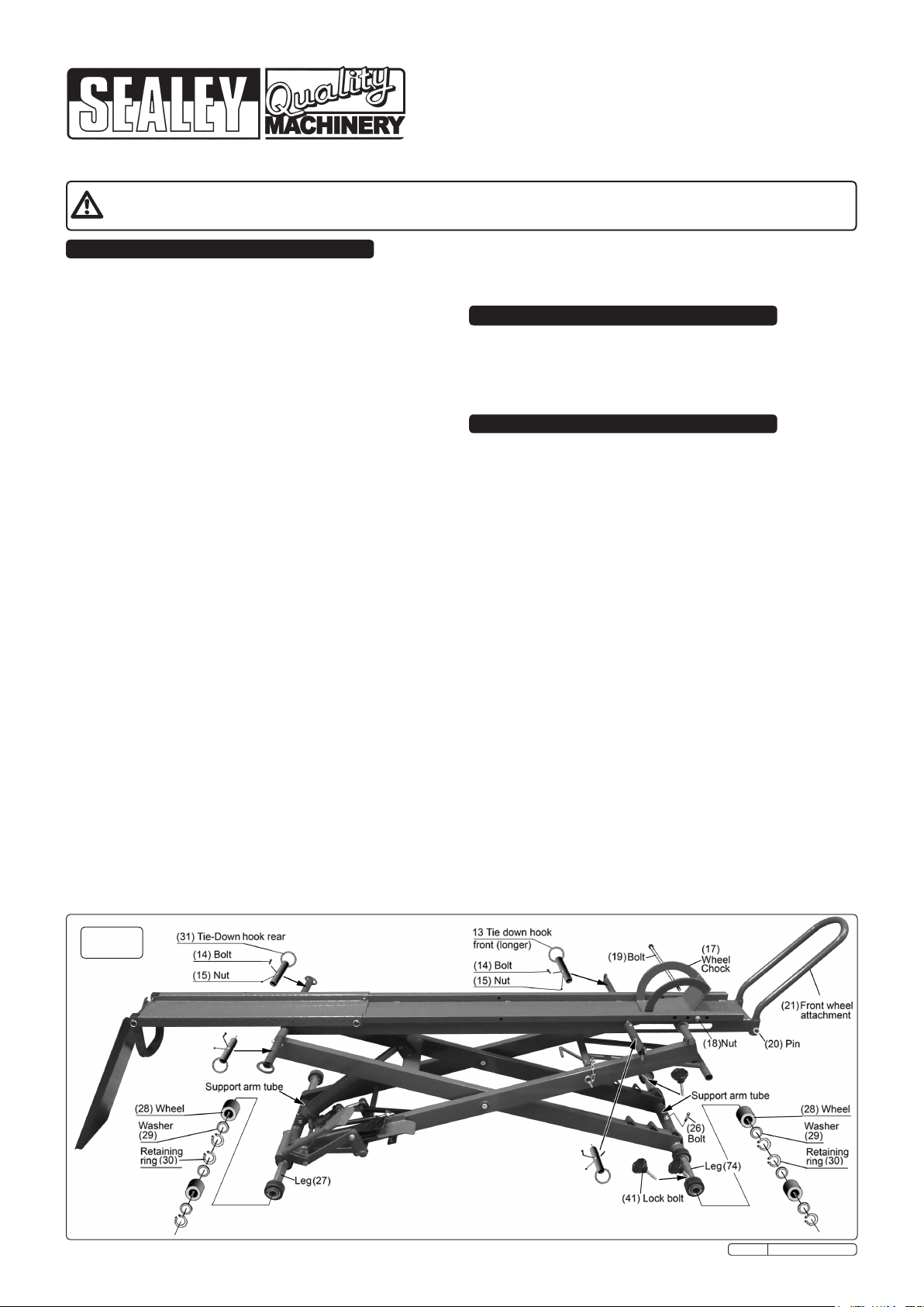
3. ASSEMBLY
The Lift comes completely assembled, except for the following
items: (Refer to the drawing below).
3.1 Tie Down Hooks: The two front tie downs are longer than the
rear pair. Slide the front tie downs (13) onto the rods either side
of the front end of the platform and secure them with bolts (14)
and nuts (15). Attach the shorter rear tie-downs (31) to the rear
rods and secure with bolts (14) and nuts (15).
3.2 Wheel Chock: Place the wheel chock (17) on to the front end
of the platform and align it with a suitable pair of holes. Slide
the long bolt (19) through a hole in the side of the platform and
through the sleeves welded to the back of the chock and out
the other side of the platform. Secure with nut (18).
3.3 Front Wheel Attachment. Drop the ends of the 'U' shaped
front wheel attachment (21) into the sleeves welded to the front
end of the platform and secure with a pin (20) on either side.
3.4 Support Leg and Wheel Assemblies: Identify the two support
leg/wheel assemblies (27) and (74). The front assembly (74)
has a threaded hole between each pair of wheels. Insert the
front assembly through the support arm tube at the lower, front
end of the scissor frame. Rotate the assembly within the tube
until the hole in the centre aligns with the hole in the tube. Secure with
a bolt (26).
3.4.1 Now attach wheels (28), washers (29) and retaining rings
(30) in the order shown in the diagram below. Identify the two
lock bolts (41) with hand wheels attached and screw them into
the holes between the wheels on either side.
3.4.2 Insert the rear assembly (27) through the support arm tube at
the lower, back end of the scissor frame. Now attach wheels
(28), washers (29) and retaining rings (30) in the order shown
in the diagram below.
fig.1
Original Language Version
MC450 Issue: 2 - 15/10/09
4. INTRODUCTION
All steel construction with foot operated, integral hydraulic
pump and ram assembly. Fitted with platform safety lock device
to prevent accidental lowering. Bike fixed by front wheel clamp,
in addition, four eyelets allow tie downs to be used for added
stability. Fitted with tyre width loading ramp. Base assembly
fitted with transport wheels allowing lift to be moved in
horizontal or vertical position. Can be stored in an upright
position to save space when not in use.
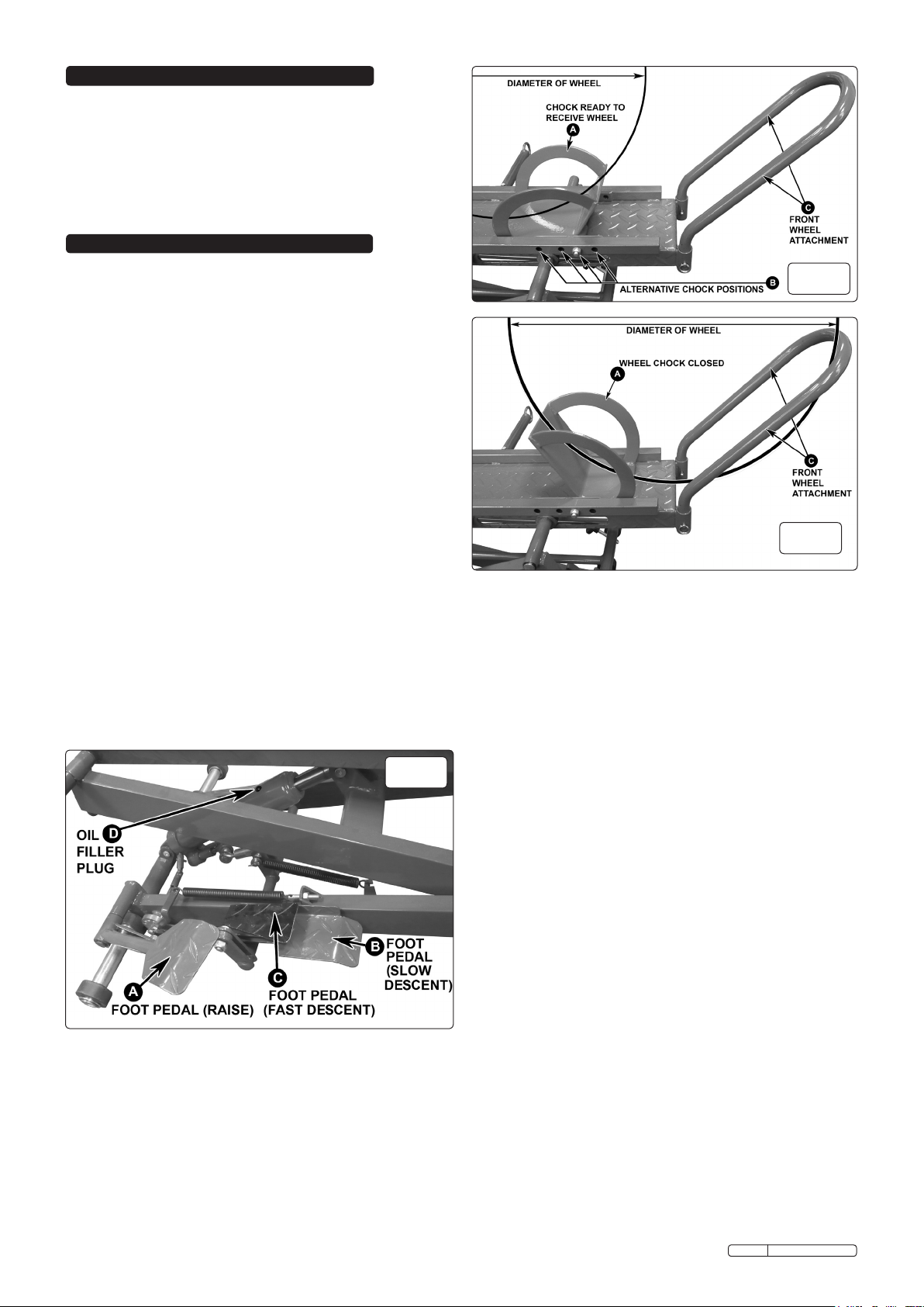
5. OPERATING INSTRUCTIONS
WARNING! Ensure that you read, understand and apply the
safety instructions before use.
WARNING! DO NOT attempt to overload the lift.
5.1 Position the lift in a suitable area, checking that the surface on
which the lift will stand is solid and flat (preferably concrete).
Bleeding the system: Whilst removing the oil ller plug from
the ram the lift must have the safety locking locking bar
engaged. Remove the locking bar pin shown in g.6B. Using the
main foot pedal (see g.2A), raise the platform until the locking
bar rides over the rst locking bar stop (see g.6). Press the
slow descent pedal (see g.2B) and allow the locking bar to
settle fully against the stop.
5.2.1 Remove the oil ller cap from the side of the ram as shown in
g.2D.
5.2.2 Raise the lift slightly so that the locking bar is no longer under
pressure. Using the locking bar lever (see g.6C) raise the
locking bar to the horizontal position and insert the locking bar
pin. Press the slow descent foot pedal (see g.2B) and allow
the lift to settle to its lowest position so that the ram is fully
retracted.
5.2.3 Fully open the release valve by depressing and holding down
the fast descent pedal (see g.2C). Now pump the main foot
pedal 6 to 8 strokes. This will help release any pressurised air
which may be trapped within the reservoir.
5.2.4 Raise the platform again, engage the safety locking bar and
reinstall the oil ller plug.
5.2.5 Check to ensure that the pump operates smoothly before
putting into service. Lubricate as instructed in the Maintenance
Section.
5.2.6 Inspect before each use. Do not use if any components are
bent, broken or cracked. components are noted.
fig.2
5.3 Loading a motorcycle: Lay the lift on a smooth flat surface
such as concrete. Press and hold down the fast decent pedal
to ensure that the ram is fully retracted and the lift is therefore
in its lowest position.
5.3.1 Extend the rear section of the platform by removing the
locking pins from the middle of the platform and pulling the
extension out until the holes in the end of the extension piece
are in line with a second set of holes for locking in the
extended position. Insert the pins to lock the extension piece.
5.3.2 Hook the loading ramp into the two slots at the end of the
extension piece and allow the free end to rest on the ground.
5.3.3 When the bike is fully on the ramp the front wheel will be
retained between the front wheel attachment (C) and the
Original Language Version
fig.3
fig.4
closed wheel chock (A) as shown in fig.4. The position of the
wheel chock can be altered to cater for different diameter
wheels by placing the pivot bolt in one of four positions as
shown in fig.3. If the front wheel is not held firmly between
the wheel chock and the front wheel attachment remove the
motorcycle from the ramp and move the chock closer to the
front wheel attachment.
5.3.4 The motorcycle must be loaded onto the centre of the loading
ramp. Failure to do this could result in the motorcycle falling
from the ramp resulting in serious injury to the operator and/
or damage to the ramp or motorcycle.
5.3.5 Ensure the wheel chock is in the ready position to receive
the motorcycle front wheel as shown in fig.3A.
5.3.6 Standing beside the motorcycle, push it up the ramp and
all the way up onto the platform. As the front wheel on the
motorcycle passes over the open wheel chock, the wheel
chock will rotate forwards. The front tyre of the motorcycle
will now be pushing down on the wheel chock, which will
rotate it into the closed position. This causes the wheel chock
to clasp the front wheel of your motorcycle in place, holding
the motorcycle upright. This is NOT a substitute for securely
tying the motorcycle onto the Lift using LOCKING RATCHET
STYLE TIE DOWN STRAPS. Please ensure that the tie
down straps are locked in place and hold the motorcycle
safely on the Lift. Failure to correctly and safely tie the
motorcycle in place will invalidate the warranty and may
cause injury or death in the event that the motorcycle was to
become dislodged from the lift.
5.4 Correct Tie-down Procedure:
5.4.1 Attach one end of the ratchet tie downs to the handlebars or
fork area. Connect the other end of the straps to the forward
outrigger tie-down rings. Ratchet the tie-down straps to
compress the motorcycle suspension until the motorcycle is
secure. This will typically require that you compress the front
suspension on your motorcycle to approximately 75% of its
full travel.
5.4.2 Secure the rear of the motorcycle in a similar manner using
an attachment point such as the frame, swing arm, passenger
foot rests e.t.c. Attach the other end of the straps to the rear
outrigger tie-down rings, and ratchet until motorcycle is
secure. Again, this will require you to compress the rear
suspension on the motorcycle until there is no possibility that
the motorcycle could become dislodged.
MC450 Issue: 2 - 15/10/09
 Loading...