

Page 1
4TONNE HORIZONTAL LOG SPLITTER 370MM CAPACITY
IMPORTANT: PLEASE READ THESE INSTRUCTIONS CAREFULLY. NOTE THE SAFE OPERATIONAL REQUIREMENTS, WARNINGS & CAUTIONS. USE
THE PRODUCT CORRECTLY AND WITH CARE FOR THE PURPOSE FOR WHICH IT IS INTENDED. FAILURE TO DO SO MAY CAUSE DAMAGE AND/OR
PERSONAL INJURY AND WILL INVALIDATE THE WARRANTY. KEEP THESE INSTRUCTIONS SAFE FOR FUTURE USE.
5TONNE LOG SPLITTER 520MM CAPACITY
MODEL NO’S: LS370H.V2 & LS520H.V2
LS520HST.V2
Thank you for purchasing a Sealey product. Manufactured to a high standard, this product will, if used according to these
instructions, and properly maintained, give you years of trouble free performance.
Refer to
instructions
Wear
protective
gloves
Wear eye
protection
Wear ear
protection
Wear
protective
clothing
Wear safety
footwear
Warning!
Warning!: No
reaching in.
Keep in dry
area protect
1. SAFETY
1.1. ELECTRICAL SAFETY
WARNING! It is the user’s responsibility to check the following:
Check all electrical equipment and appliances to ensure that they are safe before using. Inspect power supply leads, plugs and
all electrical connections for wear and damage. Sealey recommend that an RCD (Residual Current Device) is used with all electrical
products. You may obtain an RCD by contacting your local Sealey Stockist.
If the product is used in the course of business duties, it must be maintained in a safe condition and routinely PAT (Portable
Appliance Test) tested.
Electrical safety information, it is important that the following information is read and understood.
1.1.1. Ensure that the insulation on all cables and on the appliance is safe before connecting it to the power supply.
1.1.2. Regularly inspect power supply cables and plugs for wear or damage and check all connections to ensure that they are secure.
1.1.3. Important: Ensure that the voltage rating on the appliance suits the power supply to be used and that the plug is tted with the
correct fuse - see fuse rating in these instructions.
8 DO NOT pull or carry the appliance by the power cable.
8 DO NOT pull the plug from the socket by the cable.
8 DO NOT use worn or damaged cables, plugs or connectors. Ensure that any faulty item is repaired or
replaced immediately by a qualied electrician.
WARNING! Before starting any repair, maintenance or cleaning always disconnect the power.
1.1.4. This product is tted with a BS1363/A 13 Amp 3 pin plug.
If the cable or plug is damaged during use, switch the electricity supply and remove from use.
Ensure that repairs are carried out by a qualied electrician.
Replace a damaged plug with a BS1363/A 13 Amp 3 pin plug. If in doubt contact a qualied electrician.
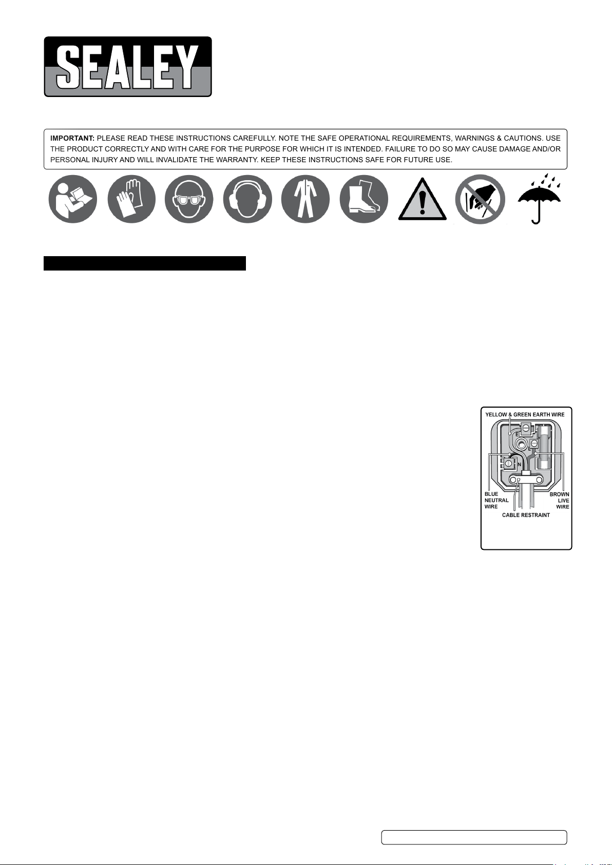
a) Connect the GREEN/YELLOW earth wire to the earth terminal ‘E’.
b) Connect the BROWN live wire to the live terminal ‘L’.
c) Connect the BLUE neutral wire to the neutral terminal ‘N’.
Ensure that the cable outer sheath extends inside the cable restraint and that the restraint is tight.
Sealey recommend that repairs are carried out by a qualied electrician.
1.2. WORKING HEIGHT
WARNING! Must only be used correct height. Log Splitter must be securely mounted so that the hold-to-run two-hand control device
shall be located so that the height control actuators shall be between 850 mm to 1650 mm from the ground.
1.3. SAFETY AND MAINTENANCE
9 Keep the log splitter clean for best and safest performance.
9 Maintain the log splitter in good condition (use an authorised service agent).
9 Prior to every use check all electrical connections, hydraulic pipes, hoses and safety / stopping devices.
9 Use a qualified person to lubricate and maintain the log splitter.
8 DO NOT use brake fluid to top up hydraulic unit.
8 DO NOT operate the log splitter if damaged.
9 Replace or repair damaged parts. Use genuine parts only. Unauthorised parts may be dangerous and will invalidate the warranty.
1.4. WORKSHOP/ENVIRONMENTAL SAFETY
9 Locate the log splitter on dry, level and solid ground in a suitable work area with adequate lighting. Fix securely in place using anchor
bolts.
9 Keep the area clean and tidy and free from unrelated materials. DO NOT leave tools, logs or other items lying around where they could
become a tripping hazard.
8 DO NOT operate the log splitter in wet or damp areas or expose it to rain.
8 DO NOT operate the log splitter in areas where fumes from paint, solvents, or flammable liquids pose a potential hazard.
1.5. OPERATOR SAFETY
9 Remove ill fitting clothing. Remove ties, watches, rings and other loose jewellery, and contain long hair.
9 Wear protective, electrically non conductive gloves.
9 Always wear safety goggles. Everyday spectacles are not sufficient protection.
9 Maintain correct balance and footing, DO NOT over-reach. Ensure the floor is not slippery and wear non-slip, protective footwear.
8 DO NOT allow untrained persons to operate the log splitter.
8 DO NOT operate the log splitter with the guards or guides removed.
© Jack Sealey Limited
Original Language Version
LS370H.V2 LS520H.V2 Issue 2 (3) 02/10/19
Recommended fuse rating
13 Amp
from rain
Page 2
8 DO NOT operate the log splitter when you are tired or under the influence of alcohol, drugs or intoxicating medication.
8 DO NOT attempt to load a log until the log pusher has returned to the stop position.
9 Stay alert and always pay attention to the movement of the machine and the work piece.
9 The log splitter must always be operated by one person only.
9 Keep hands away from the moving parts of the log splitter.
9 Keep hands away from splits and cracks which open in logs. They may close suddenly and crush or cut off parts of your hands.
WARNING! Ensure power is switched before attempting to clear jammed logs.
9 For this reason DO NOT attempt to remove jammed logs by hand. A jammed log is a log which is only partially split and continues to
grip the splitting wedge. See section 5.3 for instruction on removing jammed logs.
1.6. SAFETY OF OTHERS
8 DO NOT allow another person to help you with a jammed log.
9 Keep children and unauthorised persons away from the work area.
9 The log splitter must always be operated by one person only. Other people must keep a safe distance from the log splitter especially
when it is in operation.
9 Store the log splitter in a safe area away from children and other people not qualified to use the log splitter.
1.7. GENERAL SAFETY
8 DO NOT make any modifications to the log splitter.
8 DO NOT leave the machine unattended when running.
8 DO NOT exceed the stated log capacity of the log splitter.
8 DO NOT use the log splitter for a task it is not designed to perform.
8 DO NOT leave the log splitter until the splitting wedge has returned to the start position.
8 DO NOT force the log splitter to work beyond its specified capacity.
9 Ensure that there are no nails, screws or other foreign objects in logs to be split.
9 The end of logs should be cut square
9 Logs should not be of an irregular shape.
WARNING! The warnings, cautions and instructions referred to in this manual cannot cover all possible conditions and situations that
may occur. It must be understood that common sense and caution are factors which cannot be built into this product, but must be
applied by the operator.
2. INTRODUCTION
2.1. LS370H.V2/ LS520H.V2
Safe and easy way to split logs, offering continuous sizing and up to 4tonne LS370H.V2 and 5tonnes LS520H.V2 of pressure. Splits
logs almost instantly upon contact, keeping labour and work time to a minimum. Features a two hand safety operation push-button
and lever. Fitted with a new CE standard guard.
3. SPECIFICATION
Model No: ...................................................................... LS370H.V2 .......................................................... LS520H.V2
Maximum Load Pressure: ......................................................4tonne ..................................................................5tonne
Maximum Log Diameter: .................................................... Ø250mm .............................................................. Ø250mm
Maximum Log Length: ........................................................... 370mm .................................................................520mm
Minimum Log Diameter: ....................................................... Ø50mm ................................................................ Ø50mm
Minimum Log Length: ............................................................ 130mm .................................................................200mm
Motor Power: .............................................................. 1500W - 230V ......................................................2200W - 230V
Overall Size (W x D x H): ...................................750 x 250 x 420mm ............................................. 940 x 270 x 510mm
4. ASSEMBLY
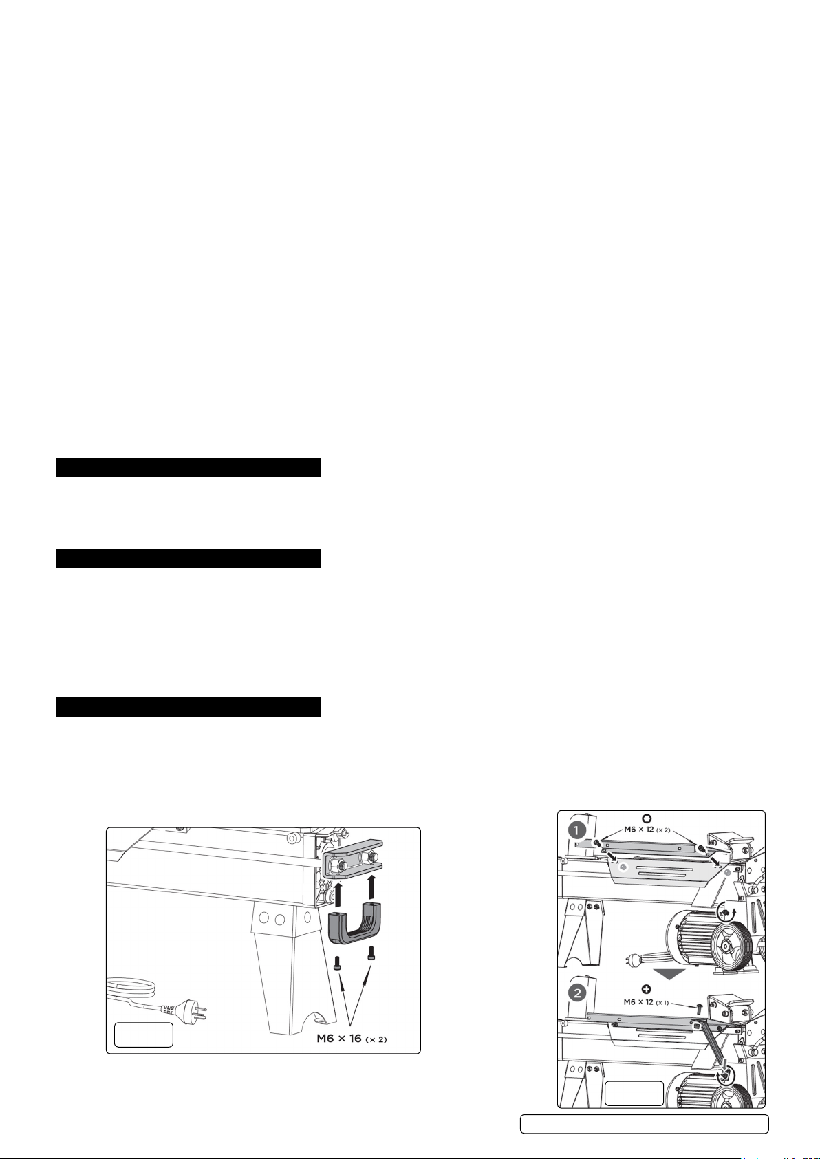
4.1. LIFTING HANDLE (FIG.1)
4.1.1. Mount the lifting handle to the U bracket with two M6×16 bolts.
4.2. LOG TRAY (FIG.2)
4.2.1. Mount the guard bottom plate to rear guiding plate and secure with two M6×12 socket head cap screws and locknuts. Loosen
the socket head cap screw and big washer on the wheel bracket, insert the open end of support strut 2 (g2.2) between the big
washer and wheel bracket and tighten screw. Connect the upper end of support strut 2 (g2.2) to the guard bottom plate with cross
recessed pan head screw M6×12 and locknut M6 and then tighten it.
g.1
© Jack Sealey Limited
Original Language Version
g.2
LS370H.V2 LS520H.V2 Issue 2 (3) 02/10/19
Page 3
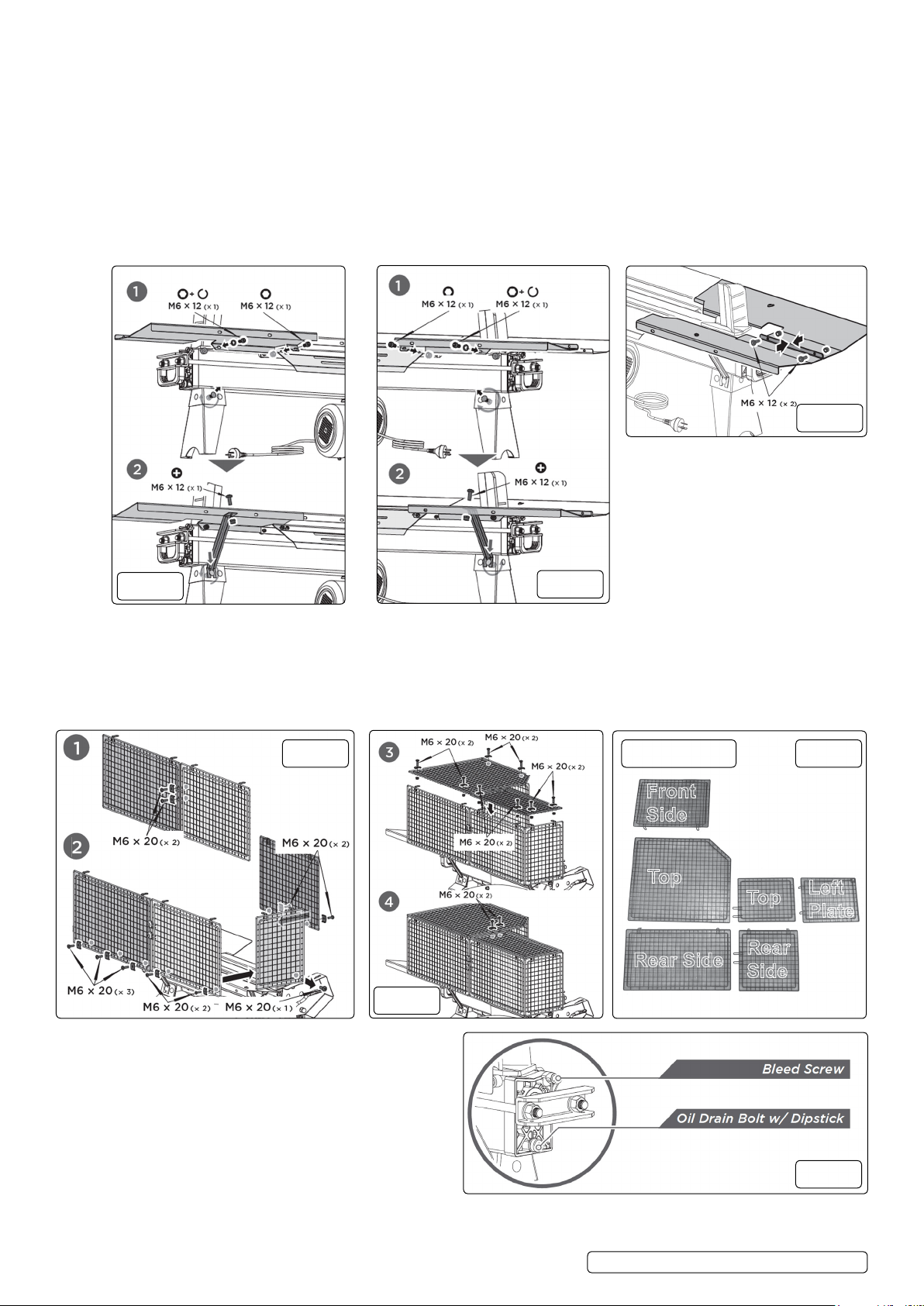
4.2.2. Align the two mounting holes of the log tray 1 (g.2.1) to the holes on rear side of the splitter. Insert one socket head cap screw
Top
Top
Front
Side
Rear
Side
Rear Side
Left
Plate
M6×12 and spring washer into the mounting hole on left side and the other socket head cap screw M6×12 and locknut M6 on right
side and securely tighten both. Loosen the cup head bolt and nut on left side of the front leg, insert the open end of support strut 1
onto the bolt and then tighten the nut. Connect the upper end of support strut 1 to the log tray 1 with cross recessed pan head screw
M6×12 and locknut M6 and then tighten it (g.3).
4.2.3. Align the two mounting holes of the log tray 2 to the holes on front side of the splitter. Insert one socket head cap screw M6×12 and
spring washer into the mounting hole on right side and the other socket head cap screw M6×12 and locknut M6 on left side and
securely tighten both. Loosen the cup head bolt and nut on right side of the front leg (g 4.1), insert the open end of support strut 1
onto the bolt and then tighten the nut. Connect the upper end of support strut 1 to the log tray 2 with cross recessed pan
head screw M6×12 and locknut M6 and then tighten it (g.4.2).
4.2.4. (g.5) Connect log tray 1 and log tray 2 with two pan head M6×12 screws and locknuts.
WARNING! Must only be used correct height. Log Splitter must be securely mounted so that the hold-to-run two-hand control device
shall be located so that the height control actuators shall be between 850 mm to 1650 mm from the ground.
g.5
g.3
4.3. WIRE GUARD (FIG.6.7.8)
4.3.1. Connect two rear guard plates together with two M6×20 bolts, U-spacers and nuts (g.6.1).
4.3.2. Attach the front guard plate, left guard plate and rear guard plates to the log tray and bottom plate. Secure the front and rear plates
with M6×20 bolts, U-spacers and nuts and secure the left plate with M6×20 bolt and nut (g.6.2).
4.3.3. Mount the two top guard plates to the vertical plates with M6×20 bolts, U-spacers and nuts (g.7.3).
4.3.4. Connect two top guard plates with two M6×20 bolts, U-spacers and nuts (g 7.4).
g.6
g.4
Guard Parts
g.8
g.7
4.4. BLEEDSCREW (FIG.9)
4.4.1. Before operating the log splitter, the Bleed Screw should
be loosened by some rotations until air can go in and
out of the oil tank smoothly. Air ow through the Bleed
Screw hole should be detectable whilst the log splitter is under
operation. Before moving the log splitter, make sure the Bleed
Screw is tightened to avoid oil leaking from this point.
WARNING! Failure to loosen the bleed screw will keep
the sealed air in hydraulic system being compressed after
being decompressed. Such continuous air compression and
decompression will blow out the seals of the hydraulic system
and cause permanent damage to the log splitter.
© Jack Sealey Limited
Original Language Version
g.9
LS370H.V2 LS520H.V2 Issue 2 (3) 02/10/19
Page 4
4.5. MAX PRESSURE LIMITING SCREW (FIG.11)
4.5.1. Max pressure was set before the log splitter ex work and the max pressure limiting screw is sealed with glue to ensure the log splitter
works under pressure no more than 4 tonnes (LS370H.V2) and 5tonnes (LS520H.V2). The setting was done by qualied mechanic
with professional instruments. Unauthorized resetting will cause the hydraulic pump fail to output enough splitting pressure or RESULT
IN SERIOUS INJURY AS WELL AS DAMAGE TO THE MACHINE.
WARNING! DO NOT ADJUST THE MAX
PRESSURE LIMITING SCREW!
g.10
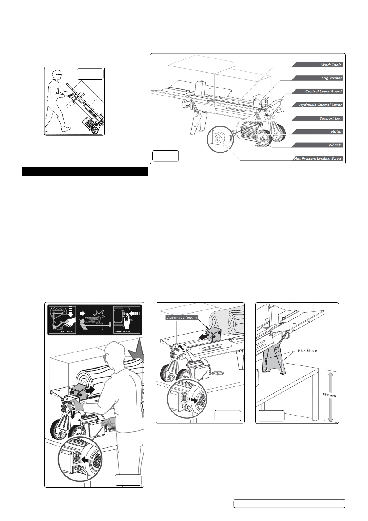
4.6. TRANSPORT (FIG.10)
4.6.1. The log splitter is equipped with 2 wheels for
minor moving. To move the log splitter to the
work site.
5. OPERATION
5.1. OPERATING CONDITIONS
5.1.1. This log splitter is a home use model. It is designed for operating under ambient temperatures between +5°C and 40°C and for
installation at altitudes no more than 1000m above M.S.L. The surrounding humidity should be less than 50% at 40°C. It can
be stored or transported under ambient temperatures between -25°C and 55°C. Before operation, put the log splitter on a 72-85cm
high, stable, at and level work bench or high stand and make sure it is bolted to the ground. Fix the support leg of the log splitter with
two bolts M8X35(A) on to a worktop between 720mm and 820mm above the ground (g.14).
WARNING! Must only be used correct height. Log Splitter must be securely mounted so that the hold-to-run two-hand control device
shall be located so that the height control actuators shall be between 850 mm to 1650 mm from the ground.
5.2. SPLITTING - TWO HANDS OPERATION (FIG.12)
5.2.1. This log splitter is equipped with “ZHB” control system that requires to be operated by both hands of the user: Left hand controls the
hydraulic control lever while right hand controls the push button switch. The log splitter will freeze upon absence of either hand. Only
after both hands release the controls, the log pusher starts to return backward to the starting position (g.13).
5.2.2. Trigger type lock-out device is adopted to avoid accidental Hydraulic Control Lever pushdown. To operate the Hydraulic Control Lever,
draw the Trigger backward with the index nger before pushing the Hydraulic Control Lever forward.
WARNING! Never force the log splitter for more than 5 seconds by keeping pressure on it to split excessively hard wood.
5.2.3. After this time interval, the oil under pressure will be overheated and the machine could be damaged. For such extremely hard log,
rotate it by 90° to see whether it can be split in a different direction. Always set logs rmly on the log retaining plates and work table.
Make sure logs will not twist, rock or slip while being split.
g.11
© Jack Sealey Limited
g.12
Original Language Version
g.13
g.14
LS370H.V2 LS520H.V2 Issue 2 (3) 02/10/19
Page 5
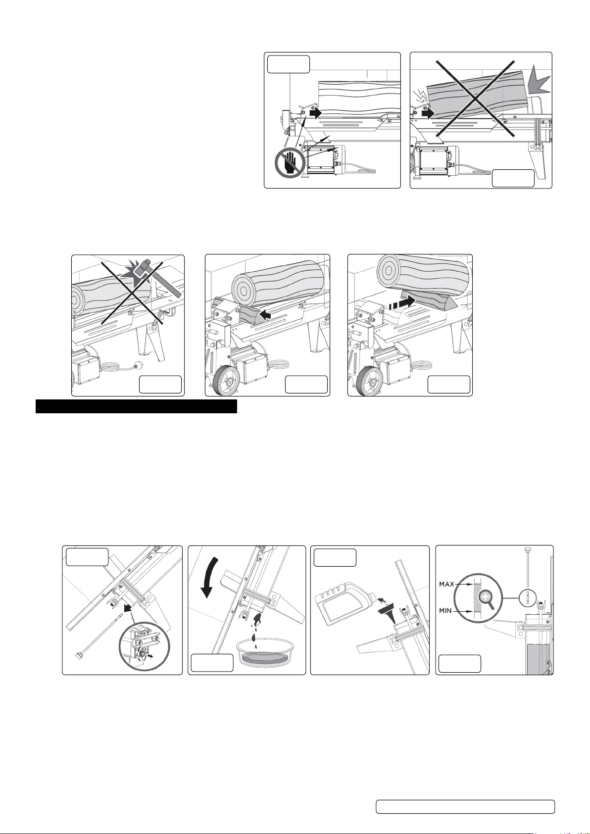
WARNING! If you are not able to split the log, this means that its hardness exceeds the capacity of the machine and thus that log
should be discarded to protect the log splitter.
8 DO NOT force the blade by splitting the log on
the upper part. This will break the blade or
damage the machine (g.16).
9 Break log in the direction of its growing grain.
8 DO NOT place log across the log splitter for
splitting. It may be dangerous and may seriously
damage the machine.
8 DO NOT attempt to split 2 pieces of log at the same
time. One of them may y up and hit you.
▲ DANGER! Keep your hands away from splitting
area, live area and heating area while working!
(g.15).
5.3. FREEING A JAMMED LOG (FIG.17)
8 DO NOT try to knock the jammed log off. Knocking about will damage the machine or may launch the log and cause an accident.
5.3.1. Release both controls.
5.3.2. After the log pusher moves back and completely stops at its starting position, insert a wedge wood under the jammed log (g.18).
5.3.3. Start the log splitter to push the wedge wood to go completely under the jammed one (g.19).
5.3.4. Repeat above procedure with sharper slope wedge woods until the log is completely freed.
g.15
g.16
g.17 g.18 g.19
6. MAINTENANCE
6.1. REPLACING HYDRAULIC OIL
Replace the Hydraulic oil in the log splitter after every 150 hours of use with a good quality oil such as Sealey HJO5LS. Take the
following steps to replace it.
WARNING! Make sure all moving parts stop and the log splitter is unplugged.
6.1.1. Unscrew Oil Drain Bolt with Dipstick to remove it (g.20).
6.1.2. Turn the log splitter on the Support Leg side over a 4 litres capacity container to drain the hydraulic oil off (g.21).
6.1.3. Turn the log splitter on the motor side.
6.1.4. Rell fresh hydraulic oil at the volume as per the hydraulic oil capacity of particular model (g.22).
6.1.5. Clean the surface of Dipstick on the Oil Drain Bolt and put it back into the oil tank while keeping the log splitter vertical (g.22).
6.1.6. Make sure the level of the relled oil is just between 2 grooves around the Dipstick (g.23).
6.1.7. Clean the Oil Drain Bolt before threading them back. Make sure they are tightened to avoid leakage before placing the log splitter
horizontally.
g.20
g.21
g.22
g.23
6.2. OIL LEVEL
6.2.1. Use a drain pan to aid in the removal of all used oil and particles (g.21). Remove oil drain plug (g.20) to drain oil from the hydraulic
transmission system. Examine oil for metal chips as a precaution to future problems.
6.3. SHARPENING WEDGE
6.3.1. This log splitter is equipped with a reinforced splitting wedge, which has a blade which is specially treated. After long periods of
operation, and when required; sharpen the wedge using a ne-toothed le removing any burrs or at spots on the edge.
© Jack Sealey Limited
Original Language Version
LS370H.V2 LS520H.V2 Issue 2 (3) 02/10/19
Page 6

7. TROUBLESHOOTING
PROBLEM PROBABLE CAUSE REMEDY SUGGESTED
Fails to split logs Log is improperly positioned. Refer to “Log Splitter Operation” section for
perfect log loading.
The log pusher moves jerkily, making
unfamiliar noise or vibrating a lot
Oil leaks around cylinder ram or from other
points
The sizes or hardness of the log exceeds the
capacity of the machine.
Wedge cutting edge is blunt. Refer to “Sharpening Wedge” section to
Oil leaks. Locate leak(s) and contact the Stockist.
Unauthorized adjustment was made on Max.
Pressure Limiting Screw. Lower max pressure
rating was set.
Lack of hydraulic oil and excessive air in the
hydraulic system.
Air sealed in hydraulic system while
operating.
Bleed Screw is not tightened before moving
the log splitter.
Oil Drain Bolt with Dipstick is not tight. Tighten the Oil Drain Bolt with Dipstick.
Hydraulic Control Valve Assembly and / or
seal(s) worn.
Reduce the log sizes before splitting it on the
log splitter.
sharpen the cutting edge.
Contact the Stockist.
Check oil level for possible oil relling.
Contact the Stockist.
Loosen Bleed Screw by 3 ~ 4 rotations before
operating the log splitter.
Tighten the Bleed Screw up before moving
the log splitter.
Contact the Stockist
HORIZONTAL LOG SPLITTER STAND FOR LS370H.V2 AND LS520H.V2
MODEL NO: LS520HST.V2
8. STAND SAFETY
9 Familiarise yourself with this product, application and limitations.
9 Maintain the stand in good condition.
9 Replace or repair damaged parts. Use recommended parts only. Non authorised parts may be dangerous and will invalidate the
warranty.
9 Keep the stand clean for best and safest performance.
9 Ensure the wood splitter is correctly secured on the stand before commencing work activity.
9 Ensure the ground is strong enough to withstand the weight of the stand, splitter and logs.
9 Maintain correct balance and footing. Ensure the oor is not slippery and wear non-slip steel toe-capped shoes/boots.
9 Keep children and unauthorised persons away from the working area.
8 DO NOT use the stand for any purpose other than tting log splitter Model No. LS370H.V2 and LS520H.V2.
8 DO NOT make any modications to the stand.
8 DO NOT use the stand if any parts are missing.
8 DO NOT exceed the rated capacity of the wood splitter.
8 DO NOT use as a platform.
9 When not in use, stand or store in a safe, dry location.
WARNING! The warnings, cautions and instructions in this manual cannot cover all possible conditions and situations that may occur.
It must be understood by the operator that common sense and caution are factors which cannot be built into this product, but must be
applied by the operator.
WARNING! Must only be used correct height. Log Splitter must be securely mounted so that the hold-to-run two-hand control device
shall be located so that the height control actuators shall be between 850 mm to 1650 mm from the ground.
9. INTRODUCTION
Powder coated steel frame for added corrosion resistance. Suitable for attaching Model No. LS520H.V2 and LS370H.V2 Horizontal Log Splitter.
Labour and work time are kept to a minimum by creating a suitable working height. Attaching the wheels from Model No. LS520H and LS370H
enables easy and efcient movement of the stand.
10. SPECIFICATION
Height (with Log Splitter): ......................................... 1250mm
Height (without Log Splitter): ...................................... 740mm
© Jack Sealey Limited
Original Language Version
LS370H.V2 LS520H.V2 Issue 2 (3) 02/10/19
Page 7
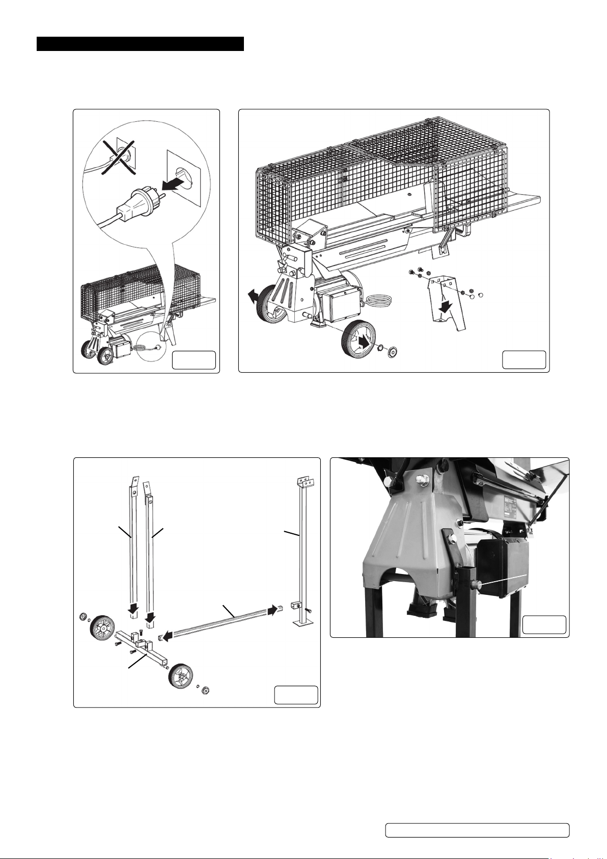
11. ATTACHING THE STAND
A
B
C
D
E
Wheel
Axle
NOTE: Stand not included
WARNING! Make sure the splitter is unplugged before mounting it to the stand (g.24).
WARNING! Make sure you have assistance when assembling the splitter stand.
11.1. Remove front stand and wheels from log splitter (g.25).
g.24
11.2. Attach the wheels from the log splitter to the stand. Attach the two uprights (g.26.A.B) to the log splitter.
11.3. The axles on the log splitter have to go through the hole in the tops of the posts (g.27) Some adjustment may be required when
attaching the legs to the splitter.
11.4. Assemble parts C, D and E (g.26) after attaching legs (g.26.A.B) to log splitter. There will be two different length bars for part D,
select the bar labelled for your log splitter.
11.5. Join the rest of the stand and the log splitter together. This step require at least two people.
NOTE: When assembling the frame you will be supplied with two different spacer bars use the one that is labelled for your splitter.
g.25
g.27
© Jack Sealey Limited
g.26
Original Language Version
LS370H.V2 LS520H.V2 Issue 2 (3) 02/10/19
Page 8

ENVIRONMENT PROTECTION
Recycle unwanted materials instead of disposing of them as waste. All tools, accessories and packaging should be sorted, taken to
a recycling centre and disposed of in a manner which is compatible with the environment. When the product becomes completely
unserviceable and requires disposal, drain any fluids (if applicable) into approved containers and dispose of the product and fluids
according to local regulations.
WEEE REGULATIONS
Dispose of this product at the end of its working life in compliance with the EU Directive on Waste Electrical and Electronic Equipment
(WEEE). When the product is no longer required, it must be disposed of in an environmentally protective way. Contact your local solid
waste authority for recycling information.
Note: It is our policy to continually improve products and as such we reserve the right to alter data, specifications and component parts without prior
notice. Please note that other versions of this product are available. If you require documentation for alternative versions, please email or call
our technical team on [email protected] or 01284 757505.
Important: No Liability is accepted for incorrect use of this product.
Warranty: Guarantee is 12 months from purchase date, proof of which is required for any claim.
Sealey Group, Kempson Way, Suffolk Business Park, Bury St Edmunds, Suffolk. IP32 7AR
© Jack Sealey Limited
Original Language Version
LS370H.V2 LS520H.V2 Issue 2 (3) 02/10/19
 Loading...