

Sealey LS370H.V2,LS520H.V2,LS520HST.V2 User Manual

4TONNE HORIZONTAL LOG SPLITTER 370MM CAPACITY
IMPORTANT: PLEASE READ THESE INSTRUCTIONS CAREFULLY. NOTE THE SAFE OPERATIONAL REQUIREMENTS, WARNINGS & CAUTIONS. USE
THE PRODUCT CORRECTLY AND WITH CARE FOR THE PURPOSE FOR WHICH IT IS INTENDED. FAILURE TO DO SO MAY CAUSE DAMAGE AND/OR
PERSONAL INJURY AND WILL INVALIDATE THE WARRANTY. KEEP THESE INSTRUCTIONS SAFE FOR FUTURE USE.
5TONNE LOG SPLITTER 520MM CAPACITY
MODEL NO’S: LS370H.V2 & LS520H.V2
LS520HST.V2
Thank you for purchasing a Sealey product. Manufactured to a high standard, this product will, if used according to these
instructions, and properly maintained, give you years of trouble free performance.
Refer to
instructions
Wear
protective
gloves
Wear eye
protection
Wear ear
protection
Wear
protective
clothing
Wear safety
footwear
Warning!
Warning!: No
reaching in.
Keep in dry
area protect
1. SAFETY
1.1. ELECTRICAL SAFETY
WARNING! It is the user’s responsibility to check the following:
Check all electrical equipment and appliances to ensure that they are safe before using. Inspect power supply leads, plugs and
all electrical connections for wear and damage. Sealey recommend that an RCD (Residual Current Device) is used with all electrical
products. You may obtain an RCD by contacting your local Sealey Stockist.
If the product is used in the course of business duties, it must be maintained in a safe condition and routinely PAT (Portable
Appliance Test) tested.
Electrical safety information, it is important that the following information is read and understood.
1.1.1. Ensure that the insulation on all cables and on the appliance is safe before connecting it to the power supply.
1.1.2. Regularly inspect power supply cables and plugs for wear or damage and check all connections to ensure that they are secure.
1.1.3. Important: Ensure that the voltage rating on the appliance suits the power supply to be used and that the plug is tted with the
correct fuse - see fuse rating in these instructions.
8 DO NOT pull or carry the appliance by the power cable.
8 DO NOT pull the plug from the socket by the cable.
8 DO NOT use worn or damaged cables, plugs or connectors. Ensure that any faulty item is repaired or
replaced immediately by a qualied electrician.
WARNING! Before starting any repair, maintenance or cleaning always disconnect the power.
1.1.4. This product is tted with a BS1363/A 13 Amp 3 pin plug.
If the cable or plug is damaged during use, switch the electricity supply and remove from use.
Ensure that repairs are carried out by a qualied electrician.
Replace a damaged plug with a BS1363/A 13 Amp 3 pin plug. If in doubt contact a qualied electrician.
a) Connect the GREEN/YELLOW earth wire to the earth terminal ‘E’.
b) Connect the BROWN live wire to the live terminal ‘L’.
c) Connect the BLUE neutral wire to the neutral terminal ‘N’.
Ensure that the cable outer sheath extends inside the cable restraint and that the restraint is tight.
Sealey recommend that repairs are carried out by a qualied electrician.
1.2. WORKING HEIGHT
WARNING! Must only be used correct height. Log Splitter must be securely mounted so that the hold-to-run two-hand control device
shall be located so that the height control actuators shall be between 850 mm to 1650 mm from the ground.
1.3. SAFETY AND MAINTENANCE
9 Keep the log splitter clean for best and safest performance.
9 Maintain the log splitter in good condition (use an authorised service agent).
9 Prior to every use check all electrical connections, hydraulic pipes, hoses and safety / stopping devices.
9 Use a qualified person to lubricate and maintain the log splitter.
8 DO NOT use brake fluid to top up hydraulic unit.
8 DO NOT operate the log splitter if damaged.
9 Replace or repair damaged parts. Use genuine parts only. Unauthorised parts may be dangerous and will invalidate the warranty.
1.4. WORKSHOP/ENVIRONMENTAL SAFETY
9 Locate the log splitter on dry, level and solid ground in a suitable work area with adequate lighting. Fix securely in place using anchor
bolts.
9 Keep the area clean and tidy and free from unrelated materials. DO NOT leave tools, logs or other items lying around where they could
become a tripping hazard.
8 DO NOT operate the log splitter in wet or damp areas or expose it to rain.
8 DO NOT operate the log splitter in areas where fumes from paint, solvents, or flammable liquids pose a potential hazard.
1.5. OPERATOR SAFETY
9 Remove ill fitting clothing. Remove ties, watches, rings and other loose jewellery, and contain long hair.
9 Wear protective, electrically non conductive gloves.
9 Always wear safety goggles. Everyday spectacles are not sufficient protection.
9 Maintain correct balance and footing, DO NOT over-reach. Ensure the floor is not slippery and wear non-slip, protective footwear.
8 DO NOT allow untrained persons to operate the log splitter.
8 DO NOT operate the log splitter with the guards or guides removed.
© Jack Sealey Limited
Original Language Version
LS370H.V2 LS520H.V2 Issue 2 (3) 02/10/19
Recommended fuse rating
13 Amp
from rain

8 DO NOT operate the log splitter when you are tired or under the influence of alcohol, drugs or intoxicating medication.
8 DO NOT attempt to load a log until the log pusher has returned to the stop position.
9 Stay alert and always pay attention to the movement of the machine and the work piece.
9 The log splitter must always be operated by one person only.
9 Keep hands away from the moving parts of the log splitter.
9 Keep hands away from splits and cracks which open in logs. They may close suddenly and crush or cut off parts of your hands.
WARNING! Ensure power is switched before attempting to clear jammed logs.
9 For this reason DO NOT attempt to remove jammed logs by hand. A jammed log is a log which is only partially split and continues to
grip the splitting wedge. See section 5.3 for instruction on removing jammed logs.
1.6. SAFETY OF OTHERS
8 DO NOT allow another person to help you with a jammed log.
9 Keep children and unauthorised persons away from the work area.
9 The log splitter must always be operated by one person only. Other people must keep a safe distance from the log splitter especially
when it is in operation.
9 Store the log splitter in a safe area away from children and other people not qualified to use the log splitter.
1.7. GENERAL SAFETY
8 DO NOT make any modifications to the log splitter.
8 DO NOT leave the machine unattended when running.
8 DO NOT exceed the stated log capacity of the log splitter.
8 DO NOT use the log splitter for a task it is not designed to perform.
8 DO NOT leave the log splitter until the splitting wedge has returned to the start position.
8 DO NOT force the log splitter to work beyond its specified capacity.
9 Ensure that there are no nails, screws or other foreign objects in logs to be split.
9 The end of logs should be cut square
9 Logs should not be of an irregular shape.
WARNING! The warnings, cautions and instructions referred to in this manual cannot cover all possible conditions and situations that
may occur. It must be understood that common sense and caution are factors which cannot be built into this product, but must be
applied by the operator.
2. INTRODUCTION
2.1. LS370H.V2/ LS520H.V2
Safe and easy way to split logs, offering continuous sizing and up to 4tonne LS370H.V2 and 5tonnes LS520H.V2 of pressure. Splits
logs almost instantly upon contact, keeping labour and work time to a minimum. Features a two hand safety operation push-button
and lever. Fitted with a new CE standard guard.
3. SPECIFICATION
Model No: ...................................................................... LS370H.V2 .......................................................... LS520H.V2
Maximum Load Pressure: ......................................................4tonne ..................................................................5tonne
Maximum Log Diameter: .................................................... Ø250mm .............................................................. Ø250mm
Maximum Log Length: ........................................................... 370mm .................................................................520mm
Minimum Log Diameter: ....................................................... Ø50mm ................................................................ Ø50mm
Minimum Log Length: ............................................................ 130mm .................................................................200mm
Motor Power: .............................................................. 1500W - 230V ......................................................2200W - 230V
Overall Size (W x D x H): ...................................750 x 250 x 420mm ............................................. 940 x 270 x 510mm
4. ASSEMBLY
4.1. LIFTING HANDLE (FIG.1)
4.1.1. Mount the lifting handle to the U bracket with two M6×16 bolts.
4.2. LOG TRAY (FIG.2)
4.2.1. Mount the guard bottom plate to rear guiding plate and secure with two M6×12 socket head cap screws and locknuts. Loosen
the socket head cap screw and big washer on the wheel bracket, insert the open end of support strut 2 (g2.2) between the big
washer and wheel bracket and tighten screw. Connect the upper end of support strut 2 (g2.2) to the guard bottom plate with cross
recessed pan head screw M6×12 and locknut M6 and then tighten it.
g.1
© Jack Sealey Limited
Original Language Version
g.2
LS370H.V2 LS520H.V2 Issue 2 (3) 02/10/19
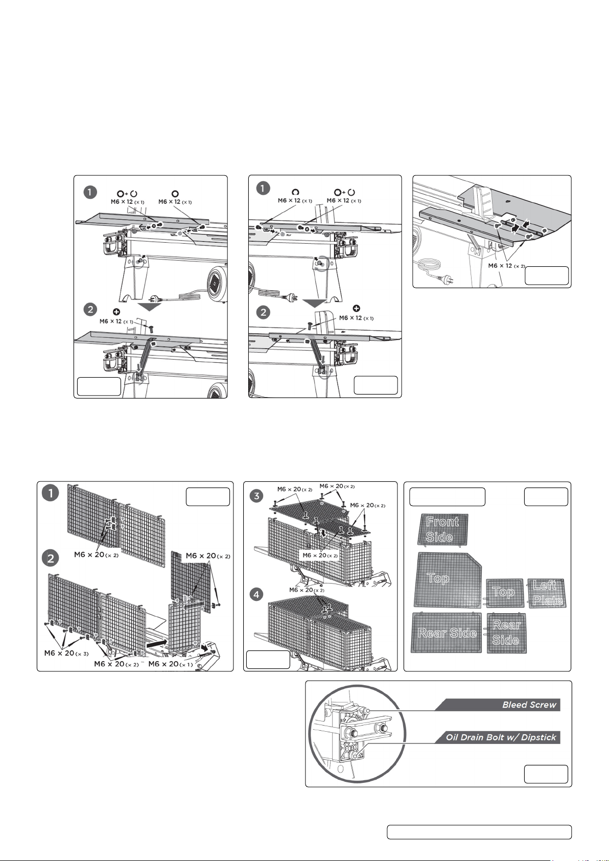
4.2.2. Align the two mounting holes of the log tray 1 (g.2.1) to the holes on rear side of the splitter. Insert one socket head cap screw
Top
Top
Front
Side
Rear
Side
Rear Side
Left
Plate
M6×12 and spring washer into the mounting hole on left side and the other socket head cap screw M6×12 and locknut M6 on right
side and securely tighten both. Loosen the cup head bolt and nut on left side of the front leg, insert the open end of support strut 1
onto the bolt and then tighten the nut. Connect the upper end of support strut 1 to the log tray 1 with cross recessed pan head screw
M6×12 and locknut M6 and then tighten it (g.3).
4.2.3. Align the two mounting holes of the log tray 2 to the holes on front side of the splitter. Insert one socket head cap screw M6×12 and
spring washer into the mounting hole on right side and the other socket head cap screw M6×12 and locknut M6 on left side and
securely tighten both. Loosen the cup head bolt and nut on right side of the front leg (g 4.1), insert the open end of support strut 1
onto the bolt and then tighten the nut. Connect the upper end of support strut 1 to the log tray 2 with cross recessed pan
head screw M6×12 and locknut M6 and then tighten it (g.4.2).
4.2.4. (g.5) Connect log tray 1 and log tray 2 with two pan head M6×12 screws and locknuts.
WARNING! Must only be used correct height. Log Splitter must be securely mounted so that the hold-to-run two-hand control device
shall be located so that the height control actuators shall be between 850 mm to 1650 mm from the ground.
g.5
g.3
4.3. WIRE GUARD (FIG.6.7.8)
4.3.1. Connect two rear guard plates together with two M6×20 bolts, U-spacers and nuts (g.6.1).
4.3.2. Attach the front guard plate, left guard plate and rear guard plates to the log tray and bottom plate. Secure the front and rear plates
with M6×20 bolts, U-spacers and nuts and secure the left plate with M6×20 bolt and nut (g.6.2).
4.3.3. Mount the two top guard plates to the vertical plates with M6×20 bolts, U-spacers and nuts (g.7.3).
4.3.4. Connect two top guard plates with two M6×20 bolts, U-spacers and nuts (g 7.4).
g.6
g.4
Guard Parts
g.8
g.7
4.4. BLEEDSCREW (FIG.9)
4.4.1. Before operating the log splitter, the Bleed Screw should
be loosened by some rotations until air can go in and
out of the oil tank smoothly. Air ow through the Bleed
Screw hole should be detectable whilst the log splitter is under
operation. Before moving the log splitter, make sure the Bleed
Screw is tightened to avoid oil leaking from this point.
WARNING! Failure to loosen the bleed screw will keep
the sealed air in hydraulic system being compressed after
being decompressed. Such continuous air compression and
decompression will blow out the seals of the hydraulic system
and cause permanent damage to the log splitter.
© Jack Sealey Limited
Original Language Version
g.9
LS370H.V2 LS520H.V2 Issue 2 (3) 02/10/19
 Loading...