

Page 1
5.5 TON LOG SPLITTER 1050MM CAPACITY
IMPORTANT: PLEASE READ THESE INSTRUCTIONS CAREFULLY. NOTE THE SAFE OPERATIONAL REQUIREMENTS, WARNINGS & CAUTIONS. USE
THE PRODUCT CORRECTLY AND WITH CARE FOR THE PURPOSE FOR WHICH IT IS INTENDED. FAILURE TO DO SO MAY CAUSE DAMAGE AND/OR
PERSONAL INJURY AND WILL INVALIDATE THE WARRANTY. KEEP THESE INSTRUCTIONS SAFE FOR FUTURE USE.
MODEL NO: LS1050V
Thank you for purchasing a Sealey product. Manufactured to a high standard, this product will, if used according to these
instructions, and properly maintained, give you years of trouble free performance.
Refer to
instructions
Wear eye
protection
Wear protective
gloves
Wear safety
footwear
Warning
crushing of
hands
Warning
1. SAFETY
1.1. ELECTRICAL SAFETY
WARNING! It is the user’s responsibility to check the following:
Check all electrical equipment and appliances to ensure that they are safe before using. Inspect power supply leads, plugs and
all electrical connections for wear and damage. Sealey recommend that an RCD (Residual Current Device) is used with all electrical
products. You may obtain an RCD by contacting your local Sealey dealer.
If the product is used in the course of business duties, it must be maintained in a safe condition and routinely PAT (Portable
Appliance Test) tested.
Electrical safety information, it is important that the following information is read and understood.
1.1.1. Ensure that the insulation on all cables and on the appliance is safe before connecting it to the power supply.
1.1.2. Regularly inspect power supply cables and plugs for wear or damage and check all connections to ensure that they are secure.
1.1.3. Important: Ensure that the voltage rating on the appliance suits the power supply to be used and that the plug is tted with the
correct fuse - see fuse rating in these instructions.
8 DO NOT pull or carry the appliance by the power cable.
8 DO NOT pull the plug from the socket by the cable.
8 DO NOT use worn or damaged cables, plugs or connectors. Ensure that any faulty item is repaired or is
replaced immediately by a qualied electrician.
1.1.4. This product is tted with a BS1363/A 13 Amp 3 pin plug.
If the cable or plug is damaged during use, switch the electricity supply and remove from use.
Ensure that repairs are carried out by a qualied electrician.
Replace a damaged plug with a BS1363/A 13 Amp 3 pin plug. If in doubt contact a qualied electrician.
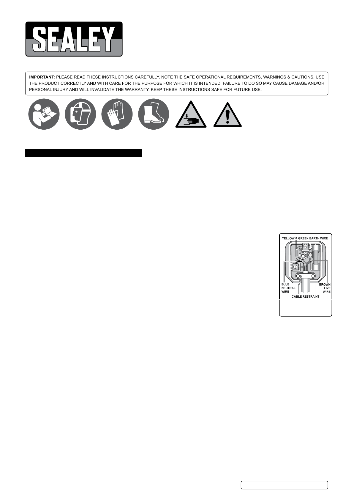
a) Connect the GREEN/YELLOW earth wire to the earth terminal ‘E’.
b) Connect the BROWN live wire to the live terminal ‘L’.
c) Connect the BLUE neutral wire to the neutral terminal ‘N’.
Ensure that the cable outer sheath extends inside the cable restraint and that the restraint is tight.
Sealey recommend that repairs are carried out by a qualied electrician.
1.2. SAFETY AND MAINTENANCE.
9 Keep the log splitter clean for best and safest performance.
9 Maintain the log splitter in good condition (use an authorised service agent).
9 Use a qualified person to lubricate and maintain the log splitter.
8 DO NOT use brake fluid to top up hydraulic unit.
8 DO NOT operate the log splitter if damaged.
9 Replace or repair damaged parts. Use genuine parts only. Unauthorised parts may be dangerous and will invalidate the warranty.
1.3. WORKSHOP/ENVIRONMENTAL SAFETY.
9 Locate the log splitter on dry, level and solid ground in a suitable work area with adequate lighting.
9 Keep the area clean and tidy and free from unrelated materials. DO NOT leave tools, logs or other items lying around where they could
become a tripping hazard.
8 DO NOT operate the log splitter in wet or damp areas or expose it to rain.
8 DO NOT operate the log splitter in areas where fumes from paint, solvents, or flammable liquids pose a potential hazard.
1.4. OPERATOR SAFETY.
9 Remove ill fitting clothing. Remove ties, watches, rings and other loose jewellery, and contain long hair.
9 Wear protective, electrically non conductive gloves .
9 Always wear safety goggles. Everyday spectacles are not sufficient protection.
9 Maintain correct balance and footing, DO NOT over-reach. Ensure the floor is not slippery and wear non-slip, protective footwear.
8 DO NOT allow untrained persons to operate the log splitter.
8 DO NOT operate the log splitter with the guards or guides removed.
8 DO NOT operate the log splitter when you are tired or under the influence of alcohol, drugs or intoxicating medication.
8 DO NOT attempt to load a log until the log pusher has returned to the stop position.
9 Stay alert and always pay attention to the movement of the log pusher.
9 The log splitter must always be operated by one person only.
9 Keep hands away from the moving parts of the log splitter.
9 Keep hands away from splits and cracks which open in logs. They may close suddenly and crush or cut off parts of your hands.
© Jack Sealey Limited
Original Language Version
LS1050V Issue 3 (HF) 25/06/18
Recommended fuse rating
13 Amp
Page 2
For this reason do not attempt to remove jammed logs by hand. A jammed log is a log which is only partially split and continues to grip
the splitting wedge.
1.5. SAFETY OF OTHERS.
8 DO NOT allow another person to help you with a jammed log.
9 Keep children and unauthorised persons away from the work area.
9 The log splitter must always be operated by one person only. Other people must keep a safe distance from the log splitter especially
when it is in operation.
9 Store the log splitter in a safe area away from children and other people not qualified to use the log splitter.
1.6. GENERAL SAFETY.
8 DO NOT make any modifications to the log splitter.
8 DO NOT exceed the stated log capacity of the log splitter.
8 DO NOT use the log splitter for a task it is not designed to perform.
8 DO NOT leave the log splitter until the splitting wedge has returned to the start position.
8 DO NOT force the log splitter to work beyond its specified capacity.
9 Ensure that there are no nails, screws or other foreign objects in logs to be split.
9 The end of logs should be cut square.
WARNING! The warnings, cautions and instructions referred to in this manual cannot cover all possible conditions and situations that
may occur. It must be understood that common sense and caution are factors which cannot be built into this product, but must be
applied by the operator.
2. INTRODUCTION
Safe and easy way to split logs, oering continuous sizing and up to 5.5tonne of pressure. Three tier table system and adjustable wedge
allows work-piece to be as near to wedge as possible minimising splitting time. Fitted with a two hand safety operation, twin pull-in and pushdown levers.
3. SPECIFICATION
Model No: ...................................... LS1050V
Tier Log Lengths ..........................540, 790, 1050mm
Maximum Log Diameter ..............................320mm
Vertical Ram Travel .................................500mm
Maximum Load Pressure .............................5.5ton
Motor Power: ......................................3000W
Overall (W x L x H): ......................565 x 840 x 1520mm
Weight: .............................................97kg
4. OPERATION
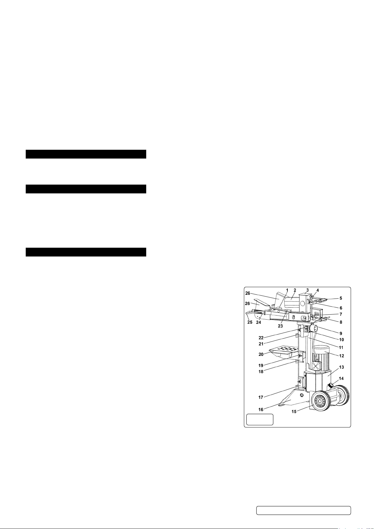
(Refer to fig.1 below). The log splitter has an electrically powered hydraulic ram situated inside the lower hollow upright steel section. The ram
is usually fully extended at rest and is connected to the upper hollow steel section behind the splitting wedge (2). When the motor is switched
on and the two control levers are operated the ram retracts and draws the splitting wedge downwards to split the log situated on the table.
4.1. Serrated Log Clamp. Grips log when pressure is applied through the control levers (24).
4.2. Splitting Wedge. After prolonged use it may be necessary to sharpen the wedge with
a fine toothed file.
4.3. Upper Steel Section (moving). Drawn downwards by ram action.
4.4. Adjustable Ram Travel Rod. Controls the ram starting point above the table.
4.5. Upper Transit Handle. Used in conjunction with lower transit handle (8) when unit
is moved
4.6. Ram Travel Rod Locking Knob. Locks ram travel rod when setting ram travel.
4.7. Control levers connection bracket. Transfers the action of the control levers to the
hydraulic system.
4.8. Lower Transit Handle. Used in conjunction with upper transit handle (8) when unit
is moved
4.9. Mains Connector Shield. Protects mains connector from ingress of dust and debris.
4.10. ON Switch. Starts electric motor.
4.11. Lower Steel Section (static). Houses the ram.
4.12. Motor. Drives pump to power hydraulic system.
4.13. Pump Housing Guard. Protects pump and hydraulic pipework.
4.14. Oil Tank Cap. Also acts as an air bleed when loosened by several turns.
4.15. Wheels. Only make contact with the ground when the unit is tipped backwards for
transit.
4.16. Base of unit. Ensure that the base is on a level and firm surface to ensure stability
of unit during use.
4.17. Lower Table Position. Ensure that table is fully inserted and hooked into position on
each side of beam.
4.18. Middle Table Position. Ensure that table is fully inserted and hooked into position on each side of beam.
4.19. Table Locking Knob. Screw fully in to lock table in each position.
4.20. Table. Ensure that table is fully inserted and hooked into position on each side of beam.
4.21. Upper Table Position. Ensure that table is fully inserted and hooked into position on each side of beam.
4.22. OFF Switch. Stops electric motor.
4.23. Serrated Log Clamp. Grips log when pressure is applied through the control levers (24).
4.24. Control levers. Used to grip the log and initiate the ram movement.
4.25. Control lever guard (Wire). Protects hands when using control levers.
4.26. Control lever shields. Protects hands when using control levers.
g.1
© Jack Sealey Limited
Original Language Version
LS1050V Issue 3 (HF) 25/06/18
Page 3
5. SET UP AND PREPARATION
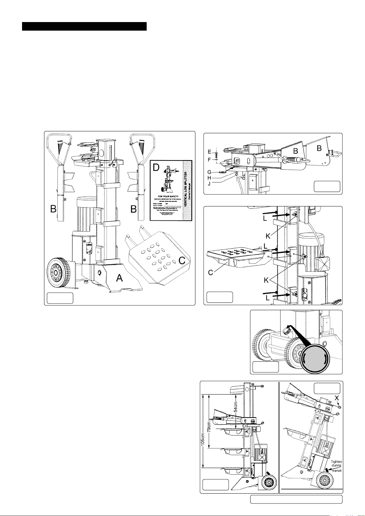
5.1. Unpacking. Open the carton and remove the Control Lever and Guard Assemblies (Bx2), the worktable (C), and the users manual
(D).
5.1.1. At least two people will be required to unpack the log splitter as it is very heavy. Lower the carton onto one of its sides and open it at
the wheels/base end of the log splitter (if necessary reseal the end already opened).
5.1.2. Fold the flap next to the wheels back onto the carton and turn the carton until this flap is trapped on the ground.
5.1.3. Fold out the other flaps and with extra help, tip the carton into an upright position so that the log splitter is resting on its base. Ensure
that the carton does not move as this is done. Lift the carton off the log splitter.
5.2. Assembly. Bolt the Control Lever and Guard Assemblies (B) to the platform on the log splitter as shown in fig.3 using Bolt (E),
Washers (F,G & H) and nut (J).
5.2.1. Ensure that the ends of the Control Lever Bracket (see fig.1-7) are inserted into the slot at the end of each Control Lever before
inserting the bolt.
5.2.2. Washer (G) should be sandwiched between each Guard Assembly and the platform as indicated in fig.3. Grease the upper face
of washer (G) before assembly.
5.2.3. Insert worktable (C) into one of the three sets of brackets (L) as shown in fig.4. At each position there is a locking knob (K) which
should be turned clockwise so that its threaded portion passes into the hole in the table (C) thus locking it in position.
g.3
g.2
g.4
5.3. Bleeding. The filler cap on the hydraulic oil tank also acts as a means of bleeding air from
the system. See fig.5. Before operating the log splitter the filler cap should be
opened by 4 turns to allow air to pass in and out of the oil tank. Air flow through the
filler cap should be detectable during operation. When moving the log splitter close the filler
cap to avoid spilling oil. Remember to open it again before the next operation.
WARNING! Failure to open the bleed screw will trap air within the system. The continued
compression and decompression of this air will blow out the seals of the hydraulic
system and cause permanent damage to the log splitter thus invalidating your warranty.
5.4. Transportation. Prior to transportation tighten the hydraulic oil tank cap to prevent spillage of
oil. Tip the log splitter back onto its wheels using the handle (see ‘X’ in fig.7 above) to transport
g.5
a
r
e
p
Loosen
O
e
r
o
f
e
Cover
B
n
,
o
i
B
t
l
e
e
d
A
i
r
the
O
u
t
it short distances. Remember to loosen the cap again before operating the log splitter.
WARNING! If using a crane to move the log splitter DO NOT use
the handle as a lifting point. If using slings they should be placed
g.7
around solid items such as the hydraulic tank or the main upright
steel section with due regard to the centre of gravity when the
unit is lifted. Slings should not be placed under the front
foot as they may damage hydraulic pipes in that area. Neither
should slings be placed under the work table or under the control
arms as they are not designed to support the weight of the whole
machine.
5.5. Work site preparation. Work safely and save effort by planning your
work site beforehand. Have the logs positioned where they can easily
be reached. Have a site located to stack the split wood or load it directly
into a suitable vehicle or trailer.
5.5.1. When cutting up wood for splitting bear in mind the capacity of
the machine for each table height being 54cm, 79cm and 105cm.
Decide which table capacity is most appropriate (see fig.6) and cut
the wood slightly shorter than the stated length. Insert the table into the
g.6
© Jack Sealey Limited
Original Language Version
LS1050V Issue 3 (HF) 25/06/18
Page 4
chosen position and turn the locking knob fully clockwise to lock it.
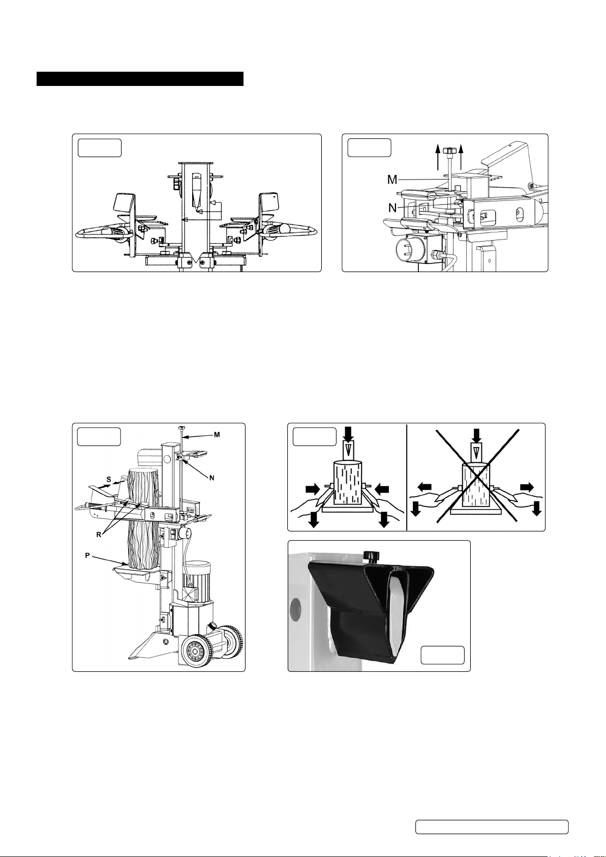
5.6. Lubrication. To aid smooth operation and prolong the working life of the unit apply a thin coat of grease to the four surfaces of the upper
moving steel section and also to the splitting wedge as indicated in fig.8.
6. OPERATING INSTRUCTIONS
WARNING! Ensure you read, understand and apply the safety instructions before use.
WARNING! This system has been designed to prevent the operator from handling the log during the splitting process. For
safety reasons the operator must not ask a second person to place or handle the log. The system is designed to be operated by
one person only.
g.8
6.1. Ensure that the power supply cable to the log splitter is routed so as not to be a tripping hazard or be positioned in such a way as to be
prone to damage or pulling.
6.2. In low temperature conditions preheat the hydraulic oil by running the motor under no load for 15 minutes prior to commencing work.
6.3. Before splitting any logs you must check that the control levers are functioning properly by doing the following tests:
6.3.1. Push down on both control levers. The splitting wedge should lower to approximately 50cm above the highest table position.
6.3.2. If either control lever is released the splitting wedge should remain in the lowered position.
6.3.3. When both levers are released the ram should rise to its highest position automatically.
6.4. When many logs of approximately the same length are to be split, the ram stroke can be set to avoid having to wait for the ram to operate
through it full stroke every time. See fig.9.
6.4.1. Hold down both control levers and move the splitting wedge down to the desired starting position being 3 to 5cm above the log to be split.
6.4.2. Release one of the control levers and switch the motor off. The splitting wedge should remain where it is.
6.4.3. Release the locking knob (N) and raise the adjusting rod (M) using the knob on its end until spring resistance is felt. Tighten the locking
knob (N).
g.9
g.10 g.11
g.12
6.4.4. When the motor is switched on the splitting wedge should remain in the position set.
6.4.5. When both control levers are held down the splitting wedge will move down to split the log and then return to the position set when both
levers are released. See also fig.10.
WARNING! Always split a log along its grain. Never attempt to split a log laid across the machine as this could be dangerous for
the operator and could seriously damage the machine.
6.4.6. Always place log on the highest feasible table position to ensure the maximum stroke of the splitting wedge through the lodge.
6.4.7. Place log onto the support table ensuring that it is vertical and sitting flat on the table as shown above at (P) in fig.10. It is essential that the
wedge and support table will contact the log square on. Never attempt to split a log if it is sitting at an angle.
6.4.8. Take hold of the control handles and move the guard assemblies inwards (see ‘S’ in fig.10 above) until the serrated log clamps (R) make
contact with the log. DO NOT press the control handles down until the log is firmly gripped as shown in fig.11.
6.4.9. Push the control levers down to start the splitting. Releasing either lever stops the motion of the splitting wedge. When both handles are
released the wedge returns to the start position.
6.4.10. Stack as you work to keep the work area hazard free. Clean up accumulated wood chips and other debris to keep the work area safe.
© Jack Sealey Limited
Original Language Version
LS1050V Issue 3 (HF) 25/06/18
Page 5
6.4.11. When work is finished allow the splitting wedge to return to the rest position and switch OFF the splitter and unplug it from the mains
supply.
6.4.12. Clean the log splitter and tidy the work area ready for the next work session.
6.5. Obtuse Wedge When longer logs are not fully split, the obtuse wedge can be fitted to assist the splitting process. The obtuse wedge slides
over the main splitting wedge and is held in place by tightening the knob on the top. The two stage wedge forces the splitting pieces further
apart to achieve a fully split log.
7. MAINTENANCE
7.1. Checking the oil. Check the oil level regularly as low oil levels can damage the pump. Sealey hydraulic oil is available in 500ml containers
(Part no: HJO500MLS) or 5ltr containers (Part no: HJO5LS).
7.1.1. Ensure the log splitter is disconnected from the mains power supply.
7.1.2. Ensure that no dirt or debris enters the oil tank.
7.1.3. Unscrew the oil filler cap which has a dipstick attached to it. The oil should reach the top of the flattened portion of the dipstick which is
equivalent to the oil being 1 to 2cm lower than the upper surface of the tank.
7.1.4. The oil should be completely changed once a year.
7.1.5. Following an oil change the log splitter should be operated a few times without actually splitting.
7.1.6. The old oil should be responsibly recycled according to local authority regulations.
7.2. Sharpening the wedge. After prolonged use the splitting wedge may become dulled. When required sharpen using a fine toothed file.
8. TROUBLESHOOTING
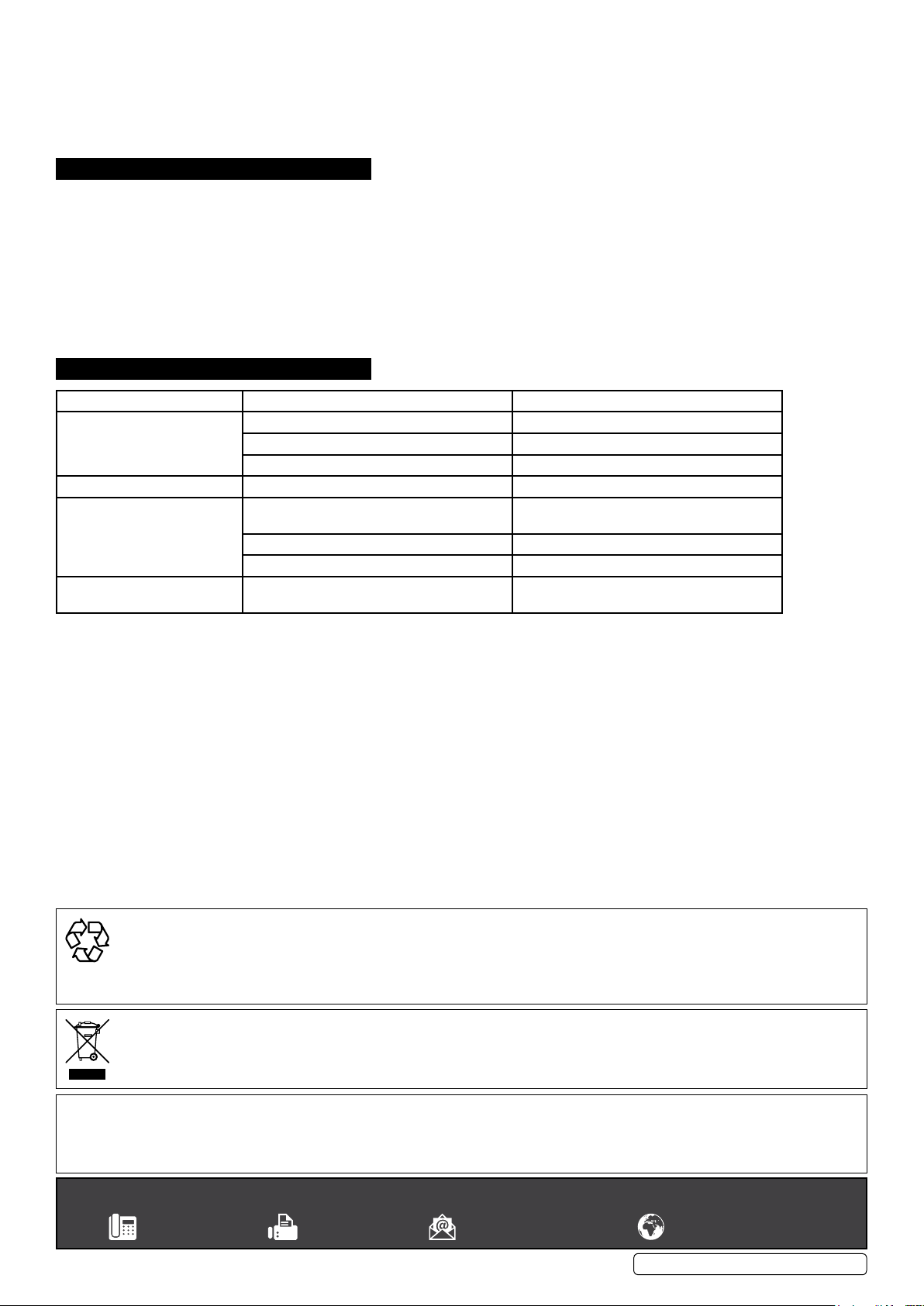
Symptom
Motor does not start. No current present. Check main fuse.
Incorrect motor rotation Incorrect connection. Contact service agent and/or electrician.
Motor is running but log splitter
does not work
Abnormal vibration and noise
when log splitter is working
POSSIBLE CAUSE SOLUTION
Extension cable defective. Unplug, check and /or replace.
Switch or capacitor defective. Contact service agent and/or electrician.
Valve not opening due to loosening of
mechanism.
Control levers or connection parts bent Repair/replace bent parts
Hydraulic oil level low Top up oil level
Hydraulic oil level low Top up oil level
Check and tighten parts
ENVIRONMENT PROTECTION
Recycle unwanted materials instead of disposing of them as waste. All tools, accessories and packaging should be sorted, taken to
a recycling centre and disposed of in a manner which is compatible with the environment. When the product becomes completely
unserviceable and requires disposal, drain any fluids (if applicable) into approved containers and dispose of the product and fluids
according to local regulations.
WEEE REGULATIONS
Dispose of this product at the end of its working life in compliance with the EU Directive on Waste Electrical and Electronic Equipment
(WEEE). When the product is no longer required, it must be disposed of in an environmentally protective way. Contact your local solid
waste authority for recycling information.
Note: It is our policy to continually improve products and as such we reserve the right to alter data, specifications and component parts without prior
notice.
Important: No Liability is accepted for incorrect use of this product.
Warranty: Guarantee is 12 months from purchase date, proof of which is required for any claim.
Sealey Group, Kempson Way, Suffolk Business Park, Bury St Edmunds, Suffolk. IP32 7AR
© Jack Sealey Limited
Original Language Version
LS1050V Issue 3 (HF) 25/06/18
 Loading...