

Sealey LP3000,LP1500.V2 Instructions Manual

INSTRUCTIONS FOR:
INFRARED QUARTZ HEATERS
MODEL No's: LP1500.V2, LP3000
Thank you for purchasing a Sealey product. Manufactured to a high standard this product will, if used according to these instructions and properly
maintained, give you years of trouble free performance.
IMPORTANT: PLEASE READ THESE INSTRUCTIONS CAREFULLY. NOTE THE SAFE OPERATIONAL REQUIREMENTS, WARNINGS, AND
CAUTIONS. USE THIS PRODUCT CORRECTLY, AND WITH CARE FOR THE PURPOSE FOR WHICH IT IS INTENDED. FAILURE TO DO SO MAY
CAUSE DAMAGE AND/OR PERSONAL INJURY AND WILL INVALIDATE THE WARRANTY.
1. SAFETY INSTRUCTIONS
1.1 ELECTRICAL SAFETY
WARNING! It is the responsibility of the owner and the operator to read, understand and comply with the following:
You must check all electrical products, before use, to ensure that they are safe. You must inspect power cables, plugs, sockets and
any other connectors for wear or damage. You must ensure that the risk of electric shock is minimised by the installation of
appropriate safety devices. A Residual Current Circuit Breaker (RCCB) should be incorporated in the main distribution board. We also
recommend that a Residual Current Device (RCD) is used. It is particularly important to use an RCD with portable products that are
plugged into a supply which is not protected by an RCCB. If in any doubt consult a qualified electrician. You may obtain a Residual
Current Device by contacting your Sealey dealer.
You must also read and understand the following instructions concerning electrical safety.
1.1.1 The Electricity at Work Act 1989 requires that all portable electrical appliances, if used on business premises, are tested by a qualified
electrician, using a Portable Appliance Tester (PAT), at least once a year.
1.1.2 The Health & Safety at Work Act 1974 makes owners of electrical appliances responsible for the safe condition of those appliances
and the safety of the appliance operators. If in any doubt about electrical safety, contact a qualified electrician.
1.1.3 Ensure that the insulation on all cables and on the appliance is safe before connecting it to the power supply. See 1.1.1 and 1.1.2
and use a Portable Appliance Tester.
1.1.4 Ensure that cables are always protected against short circuit and overload.
1.1.5 Regularly inspect power supply cables and plugs for wear or damage and check all
connections to ensure that none is loose.
1.1.6 Important: Ensure that the voltage marked on the appliance matches the power supply to be
used and that the plug is fitted with the correct fuse - see fuse rating at right.
1.1.7 DO NOT pull or carry the appliance by the power cable.
1.1.8 DO NOT pull the plug from the socket by the cable.
1.1.9 DO NOT use worn or damaged cables, plugs or connectors. Immediately have any faulty item
repaired or replaced by a qualified electrician. When a BS 1363/A UK 3 pin plug is damaged,
cut the cable just above the plug and dispose of the plug safely.
Fit a new plug according to the following instructions (UK only).
a) Connect the GREEN/YELLOW earth wire to the earth terminal ‘E’.
b) Connect the BROWN live wire to the live terminal ‘L’.
c) Connect the BLUE neutral wire to the neutral terminal ‘N’.
d) After wiring, check that there are no bare wires, that all wires have been correctly connected, that the cable outer insulation extends
beyond the cable restraint and that the restraint is tight. Double insulated products, which are always marked with this symbol ,
are fitted with live (brown) and neutral (blue) wires only. To rewire, connect the wires as indicated above - DO NOT connect either
wire to the earth terminal.
1.1.10 Products which require more than 13 amps are supplied without a plug. In this case you must contact a qualified electrician to ensure
that a suitably rated supply is available. We recommend that you discuss the installation of an industrial round pin plug and socket
with your electrician.
1.1.11 If an extension reel is used it should be fully unwound before connection. A reel with an RCD fitted is preferred since any appliance
plugged into it will be protected. The cable core section is important and should be at least 1.5mm², but to be absolutely sure that the
capacity of the reel is suitable for this product and for others which may be used in the other output sockets, we recommend the use
of 2.5mm² section cable.
1.2 GENERAL SAFETY INSTRUCTIONS
Familiarise yourself with the applications and limitations of the heater.
Ensure the heater is in good order and condition before use. If in any doubt do not use the unit and contact an electrician.
Only use recommended attachments and parts. To use unauthorised items may be dangerous and will invalidate your warranty.
Check that element guards are in place, undamaged and firmly attached.
Keep tools and other items away from the heater when it is in use.
Keep the work area clean and clear of unnecessary items.
Keep children and unauthorised persons away from the heater, as it gets very hot.
Disconnect from mains before moving or attempting any cleaning or maintenance.
DO NOT get the heater wet or use in damp or wet locations or areas where there is condensation.
DO NOT locate the heater below the power outlet.
DO NOT move the heater whilst in operation or even when still warm.
DO NOT touch the heater elements, even when cold.
DO NOT disassemble the heater for any reason. The heater must be checked by qualified personnel only.
DO NOT use this product to perform a task for which it has not been designed.
WARNING! If a fuse blows, ensure it is replaced with an identical fuse type and rating.
When not in use, store the heater carefully in a safe, dry, childproof location.
Blue
Neutral
Wire
Yellow & Green
Earth Wire
RATING 13 AMP
Brown
Live
Wire
FUSE
Cable
Restraint
Original Language Version
LP1500.V2, LP3000 Issue: 2 - 15/04/10
2. INTRODUCTION & SPECIFICATIONS
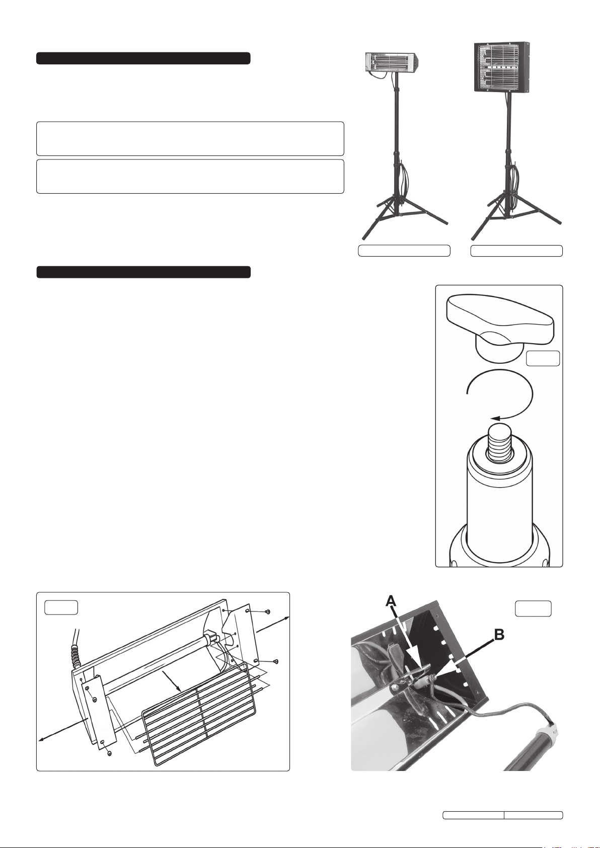
Electric, tripod mounted, heaters with infrared quartz lamps. Reach maximum heat
output within seconds of being turned on. Supplied with power cable and 3-pin plug.
A totally dry heat with no condensation, no gas, no fumes, so no smell. Ideal for
workshops, bars, forecourts or gardens and terraces if weather protected.
Model No. ..............LP1500.V2
Maximum Power: ............1500W
Minimum Power: ................. -
Model No. .................LP3000
Maximum Power: ............3000W
Minimum Power: ............1500W
Supply: ................230V – 13A
Height: ..................0.6-1.6mtr
Supply: ................230V – 13A
Height: ..................0.8-1.7mtr
LP1500.V2
3. ASSEMBLY
3.1 FITTING LAMP TO THE STAND (FIG 1)
WARNING! Isolate heater from mains before any assembling and/or maintenance operations are
carried out.
3.1.1 Place the locating hole in the lamp’s bracket onto the thread situated at the top of the stand.
3.1.2 Secure with plastic wing nut provided.
3.2 ELEMENT REPLACEMENT - LP1500.V2
WARNING! Never touch the element glass directly with fingers, only touch the ceramic ends or use a
soft cloth, otherwise the tube may get damaged.
WARNING! When removing/replacing the element, take great care not to expose the element to
excessive force as this may cause the element to fracture.
3.2.1 Remove the four screws located at each end of the face of the lamp which hold the end reflectors
and grill in place. (See fig.2)
3.2.2 Slide the element out from it’s clips (See fig.3a) taking care not to stress the attached wires. Loosen
the nut on the top of the pillar at each end of the reflector and slide out the forked connector
(See fig.3b). The element can now be removed.
3.2.3 Lay the new element on a soft cloth in front of the heater body and connect the wires at either end to
the pillars ensuring that the fork connector at the end of each wire is fully inserted between the plain
and serrated washers. Retighten the nuts at the top of each pillar.
3.2.4 Insert the new tube into the clips with the wire connections facing downwards. Ensure that the
excess loops of wire lie in the voids at either end of the casing and not on top of or underneath the
reflector.
3.2.5 Push the end reflectors on to each end of the grill and place the assembly onto the face of the main
body. Line up the holes in the end reflectors with the holes in the main body and insert the screws
finger tight. Check that there are no wires trapped or showing then tighten the screws.
LP3000
fig 1
fig 2
Original Language Version
fig 3
LP1500.V2, LP3000 Issue: 2 - 15/04/10
 Loading...