

Sealey INVMIG200LCD Instruction Manual
INSTRUCTIONS FOR:
INVERTER MIG TIG & MMA WELDER 200A
with LCD SCREEN
MODEL No: INVMIG200LCD
Thank you for purchasing a Sealey product. Manufactured to a high standard, this product will, if used according to these instructions
and maintained properly, give you years of trouble free performance.
IMPORTANT: PLEASE READ THESE INSTRUCTIONS CAREFULLY. NOTE THE SAFE OPERATIONAL REQUIREMENTS, WARNINGS & CAUTIONS. USE THE PRODUCT
CORRECTLY AND WITH CARE FOR THE PURPOSE FOR WHICH IT IS INTENDED. FAILURE TO DO SO MAY CAUSE DAMAGE AND/OR PERSONAL INJURY AND WILL
INVALIDATE THE WARRANTY. KEEP THESE INSTRUCTIONS SAFE FOR FUTURE USE.
Refer to Instruction
Manual
Wear protective
gloves
Warning:
Fumes & Gases
Warning:
Electric Shock
Warning:
Fire Risk
1. SAFETY
1.1. ELECTRICAL SAFETY
WARNING! It is the responsibility of the owner and the operator to read, understand and comply with the following:
You must check all electrical products, before use, to ensure that they are safe. You must inspect power cables, plugs, sockets and
any other connectors for wear or damage. You must ensure that the risk of electric shock is minimised by the installation of appropriate
safety devices. A Residual Current Circuit Breaker (RCCB) should be incorporated in the main distribution board. We also recommend
that a Residual Current Device (RCD) is used. It is particularly important to use an RCD with portable products that are plugged into a
supply which is not protected by an RCCB. If in any doubt consult a qualified electrician. You must also read and understand the
following instructions concerning electrical safety.
1.1.1. The Electricity at Work Act 1989 requires that all portable electrical appliances, if used on business premises, are tested by a
qualified electrician, using a Portable Appliance Tester (PAT), on a regular basis.
1.1.2. The Health & Safety at Work Act 1974 makes owners of electrical appliances responsible for the safe condition of those appliances
and the safety of the appliance operators. If in any doubt about electrical safety, contact a qualified electrician.
1.1.3. Ensure that the insulation on all cables and on the appliance is safe before connecting it to the power supply. See 1.1.1. and 1.1.2.
and use a Portable Appliance Tester.
1.1.4. Ensure that cables are always protected against short circuit and overload.
1.1.5. Inspect power supply cables and plugs regularly for wear or damage and check all connections to ensure that none are loose.
1.1.6. Important: Ensure that the voltage marked on the appliance matches the power supply to be used and that the supply is correctly
fused.
1.1.7. DO NOT pull or carry the appliance by the power cable.
1.1.8. DO NOT pull the plug from the socket by the cable.
1.1.9. DO NOT use worn or damaged cables, plugs or connectors. Have any faulty item repaired or replaced immediately by a qualified
electrician.
1.1.10 To achieve maximum output INVMIG200LCD will require a 32A fused supply. We recommend you discuss the installation of
an industrial round pin plug and socket with a competent electrician.
1.2. GENERAL SAFETY
DANGER! Unplug the welder from the electric power supply before performing maintenance or service.
Keep the welder and cables in good condition. Take immediate action to repair or replace damaged parts.
Use genuine parts and accessories only. Unapproved parts may be dangerous and will invalidate the warranty.
Use an air hose to blow out any dirt from the liner regularly and keep the welder clean for best and safest performance.
Check and spray the gas cup and contact tip regularly with anti-spatter spray, which is available from your Sealey dealer.
Locate the welder in a suitable work area. Ensure that the area has adequate ventilation as welding fumes are harmful.
Keep work area clean, tidy and free from unrelated materials. Also ensure that the work area has adequate lighting and that a fire
extinguisher is to hand.
WARNING! Use a welding head shield to protect eyes and avoid exposing skin to ultraviolet rays given off by electric arc.
Wear safety welding gauntlets.
Remove ill fitting clothing, remove ties, watches, rings and other loose jewellery and contain long hair.
Ensure that the workpiece is secured correctly before operating the welder.
Avoid unintentional contact with workpiece. Accidental or uncontrolled use of the torch may be dangerous and will wear the nozzle.
Keep unauthorised persons away from the work area. Any persons working within the area must wear protective head shield and gloves.
Operators must receive adequate training before using the welder.
Stand correctly, keeping a good footing and balance, and ensure that the floor is not slippery. Wear non-slip shoes.
Turn machine OFF when not in use.
DO NOT operate the welder if it or its cables are damaged and DO NOT attempt to fit any unapproved torch or other parts to the welder unit.
DO NOT get welder wet or use in damp or wet locations or areas where there is condensation.
DANGER! DO NOT weld near flammable materials, solids, liquids, or gases, and DO NOT weld containers or pipes which
have held such products. Avoid operating on materials cleaned with chlorinated solvents or near such solvents.
DO NOT stand welder on a metal workbench, car bodywork or similar object.
DO NOT touch any live metal parts of the torch or electrode while the machine is switched on.
DO NOT pull the welder by the cable or the torch and DO NOT bend or strain cables. Protect cables from sharp or abrasive items and
DO NOT stand on them. Protect from heat. Long lengths of slack must be gathered and neatly coiled. DO NOT place cables where they
could endanger other people.
DO NOT touch the torch or workpiece immediately after welding as they will be very hot. Allow to cool.
DO NOT operate welder while under the influence of drugs, alcohol or intoxicating medication, or if tired.
When not in use store the welder in a safe, dry, childproof area.
Warning:
Arc Rays
Warning:
Magnetic Fields
Warning:
Crushing of
Hands
© Jack Sealey Limited
Original Language Version
INVMIG200LCD ISSUE:1 - 11/08/17
1.3. GAS SAFETY
Store gas cylinders in a vertical position only and ensure that the storage area is secured correctly.
DO NOT store gas cylinders in areas where temperature exceeds 50°C. DO NOT use direct heat on a cylinder. Always keep gas
cylinders cool.
DO NOT attempt to repair or modify any part of a gas cylinder or valve and DO NOT puncture or damage a cylinder.
DO NOT obscure or remove any official cylinder labels. Always check the gas identity before use. Avoid getting gas cylinders oily
DO NOT lift a cylinder by the cap, guard or valve. Always keep caps and guards in place and close valve when not in use.
2. INTRODUCTION
Manufactured with a pressed steel outer casing, lighter than traditional models at 20kg. Fully functional LCD front panel with easy to follow
assisted set up. Inverter technology offers many advantages over traditional transformer type welders, giving greater duty cycles and more power
factor efficiency. 3-in-1 Welder uses state-of-the-art technology to achieve MIG/TIG/MMA (Arc). Suitable for arc welding a variety of rods including
rutile, basic and stainless from Ø1.6 to Ø4mm. Fan cooled DC power supply for MIG and TIG, suitable to weld steel, stainless steel, copper,
nickel, titanium and their alloys. Switchable between MIG, TIG* or MMA* welding modes (*optional extra torches required). Thermal overload
warning tells you to switch off when it exceeds maximum temperature. Wire feed control for adjusting speed of wire fed through the torch during
welding. Polarity change terminals allow for MIG or flux-cored welding. Includes 3mtr MIG torch, 3mtr earth cable, gas hose, regulator and 0.6,
0.8, 0.9, 1mm contact tips.
3. SPECIFICATION
Model No: ...........................................................................................INVMIG200LCD
Duty Cycle:MIG: .................................................................. 20%@200A, 100%@89A
TIG: ................................................................... 20%@180A, 100%@80A
MMA (Arc): ........................................................ 20%@180A, 100%@80A
Wire Capacity: ........................................................................................................5kg
Electrode Capacity: .....................................................................................Ø1.6-4mm
Absorbed Power: ............................................................................................... 8.6kW
Supply: ................................................................................................................ 230V
Insulation: ...........................................................................................................IP21S
Protection: .................................................................................................................H
Weight: ................................................................................................................. 20kg
MIG Torch: ................................................................ Euro Non-Live BINZEL® MB15*
MMA Accessory Kit (Optional): ........................................................................ MMA01
TIG Accessory Kit (Optional): .......................................................................... TIG10S
Note: ......................................................................................*Included as standard
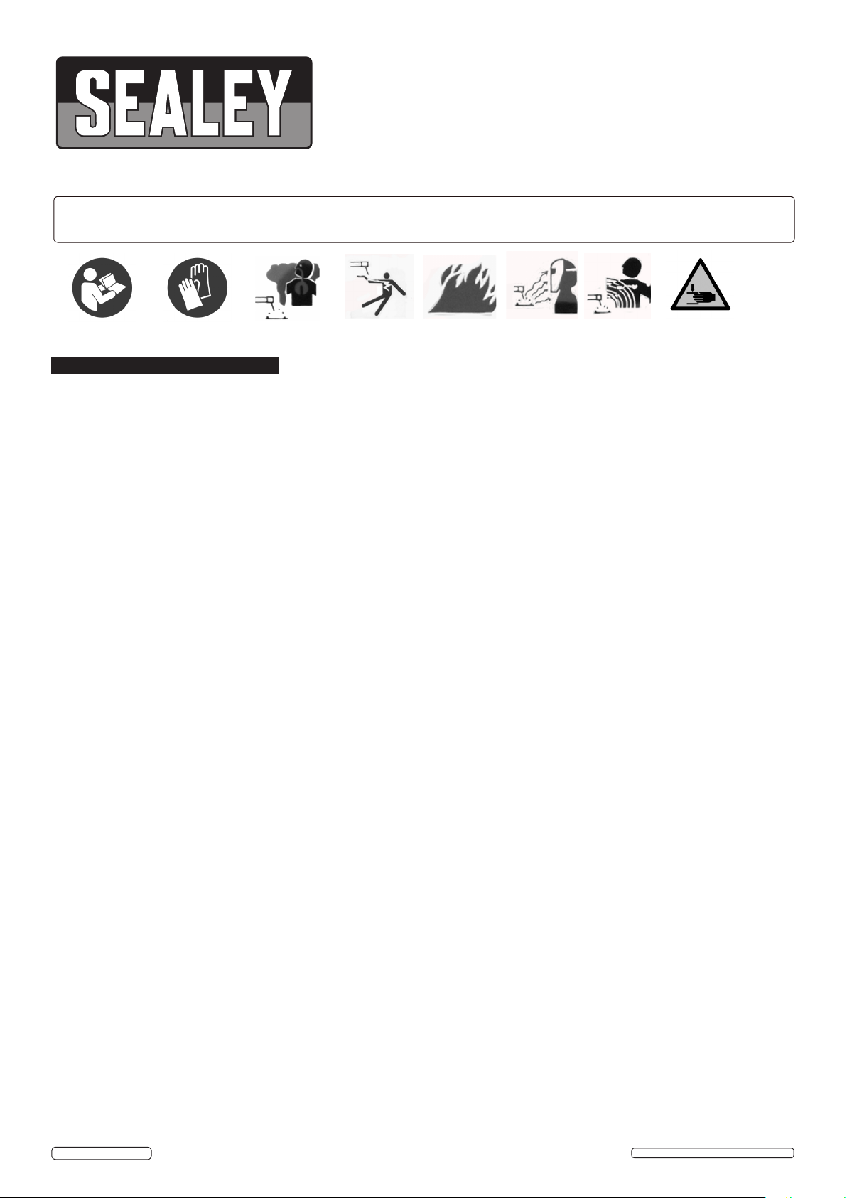
g.1
KEY TO FUNCTION SELECTORS (fig.2)
1) LCD: Displays function settings
2) Left adjustment control: Adjusts the current and wire feed speed accurately.
3) Right adjustment control: Adjusts the voltage accurately.
4) Home key: Press to return to home page.
5) Multi-function adjustment control: Selects functions; press to confirm.
6) Return: return to the previous step.
3.1. Interface descriptions
Switch machine on with the switch at the rear of the casing.
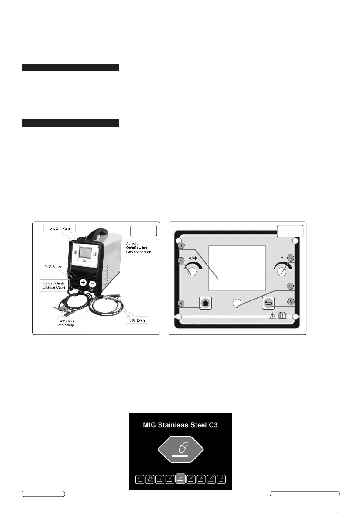
3.1.1. Multi-function selector: Total 9 functions, 8 welding functions and 1 setting. Turn multi-function control (fig.1.5) to select: press to confirm
setting.
g.2
© Jack Sealey Limited
Original Language Version
INVMIG200LCD ISSUE:1 - 11/08/17
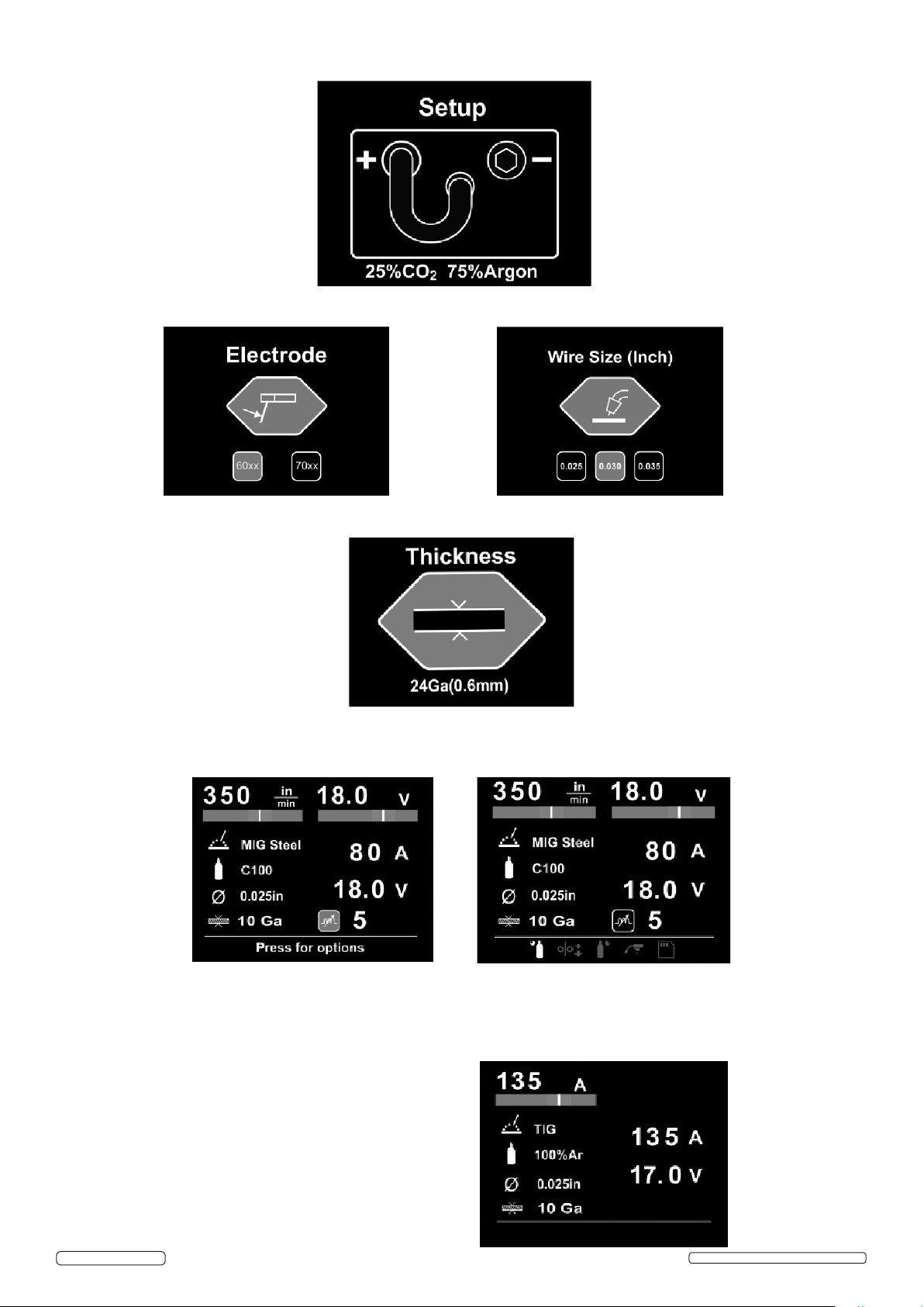
3.1.2. Output setup: Shows output connections and recommended gas mixture under different welding mode, press multi-function control to
confirm.
3.1.3. Electrode/ Wire diameter selection: Adjust multi-function control to select different electrode/wire diameter, press to confirm.
3.1.4. Material thickness: Adjust multi-function control to select different material thickness, press to confirm
3.1.5. Welding display: Shows all selected parameters.
a) When MIG welding, wire speed and voltage can be set. Adjust Multi-function control to set electro-inductance, press the control to
progress basic parameter setting.
Note 1: Basic parameter setting including: gas pre flow, wire speed, gas post flow, trigger settings, load and save function.
Note2: The green range of current and voltage shows recommended parameters.
b) When TIG welding, user can set current parameter;
Trigger settings
Spot: gives one pulse of current: may be set from 0.5sec to 9.9 sec.
2 touch: current flows as long as the trigger is pressed.
4 touch: click and release to turn on, click and release to turn off.
Load and save
Up to four settings may be stored by entering the load and save
page and selecting ‘save’. The settings can be recalled by re-visiting
the page.
© Jack Sealey Limited
Original Language Version
INVMIG200LCD ISSUE:1 - 11/08/17
 Loading...