

Sealey INVMIG160,INVMIG200 Instructions Manual

Thank you for purchasing a Sealey Welder. Manufactured to a high standard this product will, if used according to these instructions and
properly maintained, give you years of trouble free performance.
IMPORTANT: BEFORE USING THIS PRODUCT, PLEASE READ THE INSTRUCTIONS CAREFULLY. MAKE CAREFUL NOTE OF SAFETY INSTRUCTIONS,
WARNINGS
AND CAUTIONS. THIS PRODUCT SHOULD ONLY BE USED FOR ITS INTENDED PURPOSE. FAILURE TO DO SO MAY CAUSE DAMAGE
OR PERSONAL INJURY, AND WILL INVALIDATE THE WARRANTY. RETAIN THESE INSTRUCTIONS FOR FUTURE USE.
1. SAFETY INSTRUCTIONS
1.1. ELECTRICAL SAFETY
WARNING! It is the responsibility of the owner and the operator to read, understand and comply with the following:
You must check all electrical products, before use, to ensure that they are safe. You must inspect power cables, plugs, sockets and
any other connectors for wear or damage. You must ensure that the risk of electric shock is minimised by the installation of appropriate
safety devices. A Residual Current Circuit Breaker (RCCB) should be incorporated in the main distribution board. We also recommend
that a Residual Current Device (RCD) is used. It is particularly important to use an RCD with portable products that are plugged into a
supply which is not protected by an RCCB. If in any doubt consult a qualified electrician. You may obtain a Residual Current Device by
contacting your Sealey dealer. You must also read and understand the following instructions concerning electrical safety.
1.1.1. The Electricity at Work Act 1989 requires that all portable electrical appliances, if used on business premises, are tested by a
qualified electrician, using a Portable Appliance Tester (PAT), at least once a year.
1.1.2. The Health & Safety at Work Act 1974 makes owners of electrical appliances responsible for the safe condition of those appliances
and the safety of the appliance operators. If in any doubt about electrical safety, contact a qualified electrician.
1.1.3. Ensure that the insulation on all cables and on the appliance is safe before connecting it to the power supply. See 1.1.1. and 1.1.2.
and use a Portable Appliance Tester.
1.1.4. Ensure that cables are always protected against short circuit and overload.
1.1.5. Inspect power supply cables and plugs regularly for wear or damage and check all connections to ensure that none is loose.
1.1.6. Important: Ensure that the voltage marked on the appliance matches the power supply to be used and that the supply is correctly
fused.
1.1.7. DO NOT pull or carry the appliance by the power cable.
1.1.8. DO NOT pull the plug from the socket by the cable.
1.1.9. DO NOT use worn or damaged cables, plugs or connectors. Have any faulty item repaired or replaced immediately by a qualified
electrician.
1.1.10. INVMIG160 is a single phase machine and must be run from a minimum 32A supply. To achieve maximum output this model will
require a 32A fused supply. We recommend you discuss the installation of an industrial round pin plug and socket with
a qualified electrician.
Original Language Version
INSTRUCTIONS FOR:
INVERTER MIG & MMA WELDER 160A
MODEL No:
INVMIG160
1.2. GENERAL SAFETY
DANGER! Unplug the welder from the mains power supply before performing maintenance or service.
Keep the welder and cables in good condition. Take immediate action to repair or replace damaged parts.
Use genuine parts and accessories only. Unapproved parts may be dangerous and will invalidate the warranty.
Use an air hose to regularly blow out any dirt from the liner and keep the welder clean for best and safest performance.
Check and spray the gas cup and contact tip regularly with anti-spatter spray, which is available from your Sealey dealer.
Locate the welder in a suitable work area. Ensure that the area has adequate ventilation as welding fumes are harmful.
Keep work area clean, tidy and free from unrelated materials. Also ensure that the work area has adequate lighting and that a fire
extinguisher is to hand.
WARNING! Use a welding head shield to protect eyes and avoid exposing skin to ultraviolet rays given off by electric arc.
Wear safety welding gauntlets.
Remove ill fitting clothing, remove ties, watches, rings and other loose jewellery and contain long hair.
Ensure that the workpiece is correctly secured before operating the welder.
Avoid unintentional contact with workpiece. Accidental or uncontrolled use of the torch may be dangerous and will wear the nozzle.
Keep unauthorised persons away from the work area. Any persons working within the area must wear protective head shield and
gloves.
Operators must receive adequate training before using the welder.
Stand correctly, keeping a good footing and balance, and ensure that the floor is not slippery. Wear non-slip shoes.
Turn machine OFF when not in use.
DO NOT operate the welder if it or its cables are damaged and DO NOT attempt to fit any unapproved torch or other parts to the welder
unit.
DO NOT get welder wet or use in damp or wet locations or areas where there is condensation.
DANGER! DO NOT weld near flammable materials, solids, liquids, or gases, and DO NOT weld containers or pipes which
have held such products. Avoid operating on materials cleaned with chlorinated solvents or near such solvents.
DO NOT stand welder on a metal workbench, car bodywork or similar object.
DO NOT touch any live metal parts of the torch or electrode while the machine is switched on.
DO NOT pull the welder by the cable or the torch and DO NOT bend or strain cables. Protect cables from sharp or abrasive items and
DO NOT stand on them. Protect from heat. Long lengths of slack must be gathered and neatly coiled. DO NOT place cables where
they could endanger other people.
DO NOT touch the torch or workpiece immediately after welding as they will be very hot. Allow to cool.
DO NOT operate welder while under the influence of drugs, alcohol or intoxicating medication, or if tired.
When not in use store the welder in a safe, dry, childproof area.
© Jack Sealey Limited
INVMIG160 | Issue: 2S - 08/01/15
Refer to Instruction
Manual
Wear protective
gloves
Wear a welding
mask
2.1. Manufactured with a pressed steel outer casing giving this unit a weight of only 21kg. Inverter welders offer many advantages over
traditional transformer type welders. This 2-in-1 welder uses state-of-the-art technology to achieve MIG and arc welding. Automatic
Arc-Force circuitry makes this unit suitable for arc welding a variety of rods including rutile, basic and stainless steel from Ø1.6mm to
Ø4.0mm. Fan cooled DC power supply for MIG welding, suitable to weld steel, stainless steel, copper, nickel, titanium and their alloys.
Includes rocker switch to allow operator to switch between MIG and arc welding modes. Features high frequency start to enable fast
and responsive striking of the arc. Thermal overload protection which automatically switches unit off when it exceeds maximum
temperature. Fully functional front panel with self explanatory pictures for each dial and switch, making this easier and accessible to
use. Current and voltage switches to allow control of current and voltage. Wire feed control used to control the speed of wire fed
through the torch during welding. Burn back time control allows the operator to manually choose desired length of electrode wire which
protrudes from torch after welding. Polarity change terminals allow the operator to change polarity of welding torch depending on
whether the applications are MIG welding or flux-cored welding. Includes 3mtr MIG torch, 2.5mtr earth cable, gas hose and regulator
and 0.6/0.8 contact tip
2.2. IMPORTANT: These instructions contain information you require to prepare your machine for welding, together with a maintenance
section. If you have no previous experience the instructions are not intended to show you how to become a welder. Should you have no
experience, we recommend that you seek training from an expert source. MIG welding is relatively easy to perform, but does
require a steady hand and time practising under supervision with scrap metal as it is only with continued practice that you will achieve
the desired results.
1.3. GAS SAFETY
Store gas cylinders in a vertical position only and ensure that the storage area is correctly secured.
DO NOT store gas cylinders in areas where temperature exceeds 50°C. DO NOT use direct heat on a cylinder. Always keep gas
cylinders cool.
DO NOT attempt to repair or modify any part of a gas cylinder or valve and DO NOT puncture or damage a cylinder.
DO NOT obscure or remove any official cylinder labels. Always check the gas identity before use. Avoid getting gas cylinders oily or
greasy.
DO NOT lift a cylinder by the cap, guard or valve. Always keep caps and guards in place and close valve when not in use.
2. INTRODUCTION & SPECIFICATION
Model No: . . . . . . . . . . . . . . . . . . . . . . . . . . . . . . . . . . . . . . . . . . . . . . . . . . . . . . . . .INVMIG160
Duty Cycle, MIG: . . . . . . . . . . . . . . . . . . . . . . . . . . . . . . . . . . . . . . . 35% @ 160A, 60% @ 120A
Arc (MMA): . . . . . . . . . . . . . . . . . . . . . . . . . . . . . . . . . . 35% @ 160A, 60% @ 120A
Electrode Capacity: . . . . . . . . . . . . . . . . . . . . . . . . . . . . . . . . . . . . . . . . . . . . . . . . ø1.6 - 4.0mm
Maximum Wire Spool: . . . . . . . . . . . . . . . . . . . . . . . . . . . . . . . . . . . . . . . . . . . . . . . . . . . . . . 5kg
Absorbed Power: . . . . . . . . . . . . . . . . . . . . . . . . . . . . . . . . . . . . . . . . . . . . . . . . . . . . . . . . 7.8kW
Supply: . . . . . . . . . . . . . . . . . . . . . . . . . . . . . . . . . . . . . . . . . . . . . . . . . . . . . . . . . . . . . . .230V ac
Insulation: . . . . . . . . . . . . . . . . . . . . . . . . . . . . . . . . . . . . . . . . . . . . . . . . . . . . . . . . . . . . . . . . . . F
Protection: . . . . . . . . . . . . . . . . . . . . . . . . . . . . . . . . . . . . . . . . . . . . . . . . . . . . . . . . . . . . . IP21S
Weight: . . . . . . . . . . . . . . . . . . . . . . . . . . . . . . . . . . . . . . . . . . . . . . . . . . . . . . . . . . . . . . . 20.72kg
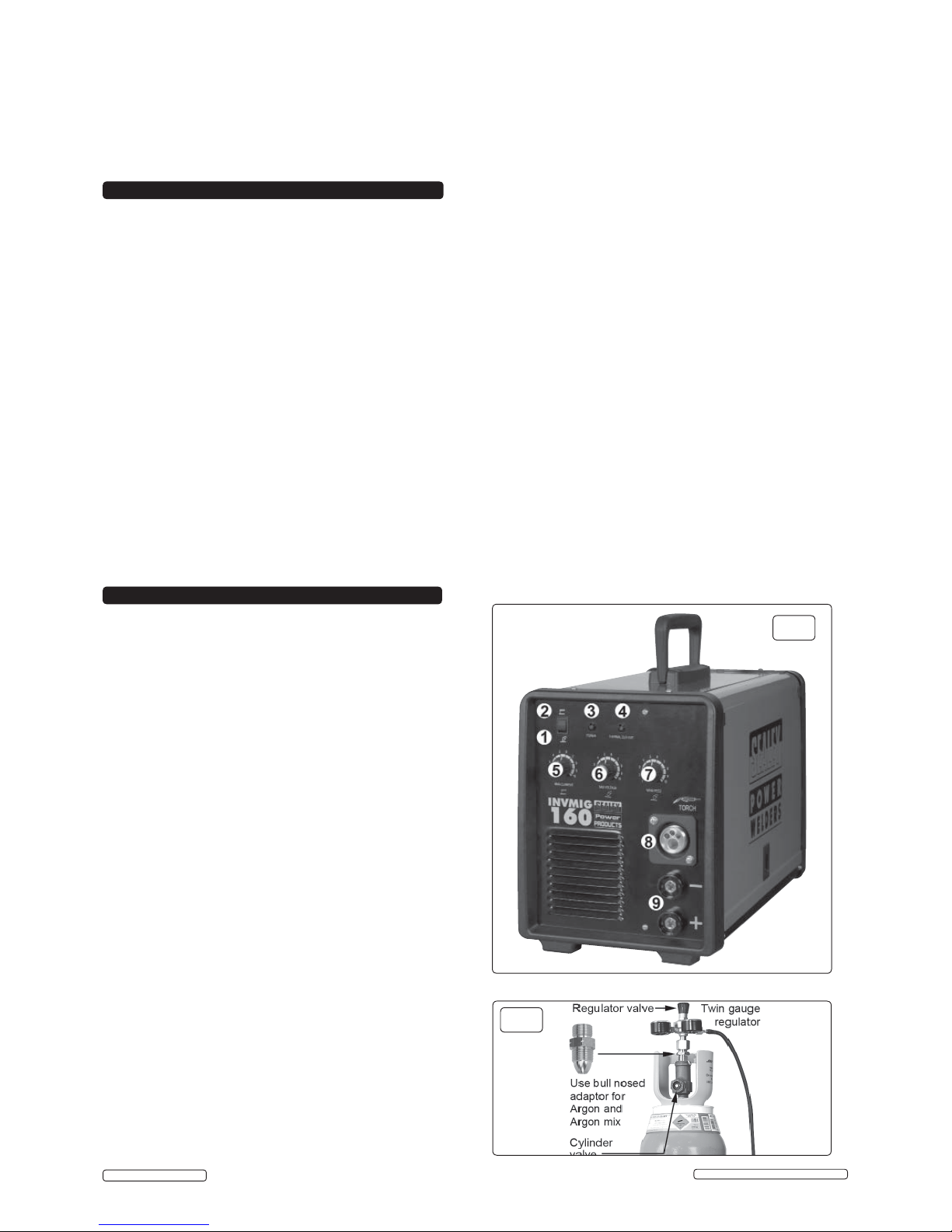
3. PREPARATION FOR MIG WELDING
NOTE: The main (On/Off) switch is located on the rear plate
of the machine.The power indicator light (fig.1.3) is lit when
the welder is live.
3.1. Switch selector switch to position 'MIG' position (fig.1.1).
3.2. COUPLING TO GAS CYLINDER.
ATTACHING THE REGULATOR. (fig.2) Whichever gas you
are using it is advisable to 'crack' the cylinder valve before
attaching the regulator. This means opening and closing the
valve very quickly in order to blow away any dust and dirt
that may have accumulated in the gas outlet. Stand to one
side whilst doing this.
3.2.1 . CO² GAS. Ensure that the threads on the gas bottle are
undamaged and free of oil and grease before attaching the
regulator. (Oil or grease in the presence of high pressure
gases can be explosive.) Ensure that the regulator has an
undamaged gasket fitted. The regulator will screw directly to
the threads on the gas bottle. Tighten with a wrench.
3.2.2. ARGON GAS OR ARGON MIXTURES. Cylinders containing
argon gas and argon mixtures have a female thread and will
require the use of a Bull Nose Adaptor to attach the regulator to
the cylinder as indicated in fig.2. Ensure that the threads on the
gas bottle are undamaged and free of oil and grease before
attaching the regulator. (Oil or grease in the presence of high
pressure gases can be explosive.) Fit the Bull Nose Adaptor
to the cylinder first and tighten with a wrench.
3.2.3. Slide a hose clip over each end of the gas hose supplied.
Push one end of the hose onto the regulator outlet and the
other end over the gas inlet spigot on the back of the welder.
Tighten the clips to ensure a good seal.
3.2.4. Close the regulator valve by turning it anticlockwise before
opening the cylinder valve. Stand to one side when opening
the cylinder valve.
3.2.5. Set the regulator flow rate to 5-8 litres/min depending on the
material to be welded, and whether there are draughts
which are strong enough to disturb the gas flow.
fi g.2
fi g.1
Original Language Version
INVMIG160 | Issue: 2S - 08/01/15
© Jack Sealey Limited
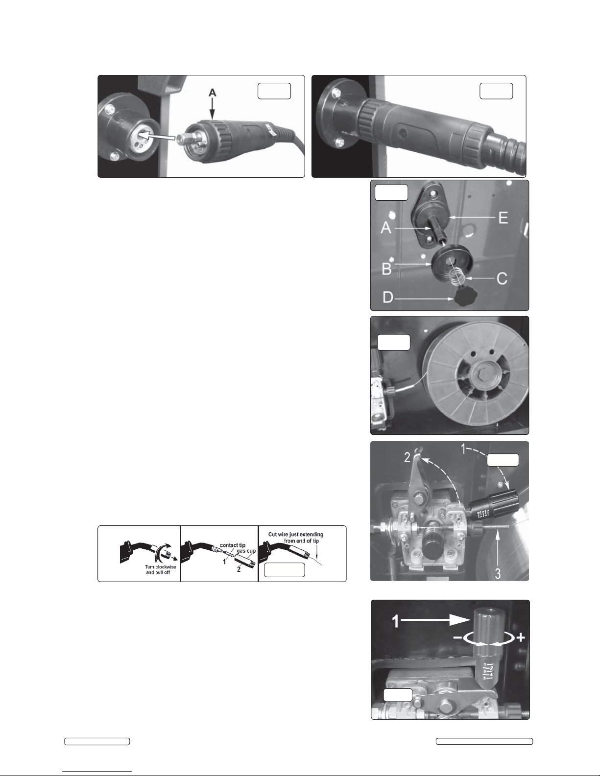
3.4. FITTING A REEL OF WIRE (FIG.5). INVMIG160 will accept up to a 5kg reel of
wire. Ensure that the wire diameter used is matched by the correct groove size in
the drive wheel and the correct tip size on the torch as well as the correct torch
liner. Failure to do this could cause the wire to slip and/or bind.
3.4.1. Remove the retaining knob (D) from the end of the spindle (A) by turning the
knob 90° anticlockwise and pulling it outwards. Remove the spring (C) and the
retaining disc (B) from the end of the spindle also. Slide the reel of wire over the
spindle and hold it against the back plate so that the hole in the reel rests on the
flange (E). Ensure that the wire is coming off the top of the reel in the direction of
the wire drive unit as shown in fig.6.
3.4.2. Retain hand pressure on the reel to keep it on the flange and slide the retaining
disc (B) over the end of the spindle and into the hole in the reel. Note that the disc
(B) has a hexagonal hole in it which fits onto the hexagonal portion of the spindle.
Keep the disc under hand pressure to retain the reel. Place the spring (C) over
the spigot of the retaining knob (D). Match the indented end of the spigot to the
hole in the end of the spindle. Push the knob spigot into the end of the spindle,
against spring pressure and turn it through 90° to lock it in place.
3.5. FEEDING WIRE THROUGH TO TORCH. Open the wire feed mechanism by
pushing the locking/wire tension knob (fig.7.1) down to the right allowing the
pressure roller carrier (fig 7.2) to spring up revealing the feed roller.
Ensure that the required feed groove (0.6 or 0.8) is in line with the wire path. See
Section 3.7. on how to reverse or change the roller.
3.5.1. Release the wire from the reel and cut off any bent portion ensuring that there are
no burrs left on the end of the wire. Keep the wire under tension at all times to
prevent it uncoiling.
3.5.2. Straighten about 40-50mm of wire and push it gently through the flexible metal
sheathed cable (fig7.3) and through the 0.6 or 0.8mm feed roller groove and on
into the torch cable liner.
3.5.3. Push down the pressure roller carrier onto the wire feed roller and hold it down.
Lift up the locking/wire tension knob so that it enters the slot in the pressure
roller carrier and snaps into the indent in its top surface (fig.7). Rotate the tension
knob to a medium setting i.e. between 2 and 3.
3.5.4.
3.5.4.
Remove gas cup (fig.8.2) and contact tip (fig.8.1) from end of torch as follows:
Remove gas cup (fig.8.2) and contact tip (fig.8.1) from end of torch as follows:
a) Take torch in left hand with the torch tip facing to the right.
a) Take torch in left hand with the torch tip facing to the right.
b) Grasp gas cup firmly in your right hand.
b) Grasp gas cup firmly in your right hand.
c) Turn gas cup clockwise only and pull it off end of torch tip.
c) Turn gas cup clockwise only and pull it off end of torch tip.
WARNING!
WARNING!
do not turn gas cup anti-clockwise, as this will damage the
do not turn gas cup anti-clockwise, as this will damage the
internal spring.
internal spring.
d) Unscrew copper contact tip (right hand thread) to remove.
d) Unscrew copper contact tip (right hand thread) to remove.
fi g.5
fi g.6
fig.7
fig.8
fi g.3 fi g.4
3.3. CONNECTING THE TORCH CABLE TO THE WELDER. Align the pins on the Euro connector with the socket on the welder front
panel as shown in fig.3. Push the connector into the socket and rotate the locking ring (A) clockwise so that it draws the plug into the
socket as shown in fig.4.
Note: damage to torches and cables is not covered by warranty.
3.5.5 Check welder is switched off and that the earth clamp is away from the torch
3.5.5 Check welder is switched off and that the earth clamp is away from the torch
tip. Connect the welder to the mains power supply and set the voltage switch
tip. Connect the welder to the mains power supply and set the voltage switch
(fig1.6) to '1'.
(fig1.6) to '1'.
3.5.6 Set the wire speed knob to position (fig1.7) 5 or 6. Keep the torch cable as
3.5.6 Set the wire speed knob to position (fig1.7) 5 or 6. Keep the torch cable as
straight as possible and press the torch switch. The wire will feed through the
straight as possible and press the torch switch. The wire will feed through the
torch.
torch.
3.5.7 a) Take torch in left hand, slide the contact tip over the wire and screw back
3.5.7 a) Take torch in left hand, slide the contact tip over the wire and screw back
into place.
into place.
b) Grasp gas cup in right hand, push onto torch head and turn clockwise only.
b) Grasp gas cup in right hand, push onto torch head and turn clockwise only.
Do not turn gas cup anti-clockwise, as this will damage the internal spring.
Do not turn gas cup anti-clockwise, as this will damage the internal spring.
c) Cut wire so that it is just protruding from the cup.
c) Cut wire so that it is just protruding from the cup.
3.6
3.6
SETTING WIRE TENSION
SETTING WIRE TENSION
.. Adjust the wire tension by rotating the wire tension
Adjust the wire tension by rotating the wire tension
knob. Turn clockwise to increase the tension and anticlockwise to decrease the
knob. Turn clockwise to increase the tension and anticlockwise to decrease the
tension. See fig 9.1.
tension. See fig 9.1.
IMPORTANT:
IMPORTANT:
Too little or too much tension will cause problematic wire feed
Too little or too much tension will cause problematic wire feed
and result in poor welding.
and result in poor welding.
fi g.9
Original Language Version
© Jack Sealey Limited
INVMIG160 | Issue: 2S - 08/01/15
 Loading...