

Sealey IMIG160,IMIG180 Instruction Manual
1.1. ELECTRICAL SAFETY
WARNING! It is the user’s responsibility to read, understand and comply with the following: You must check all electrical equipment and
appliances to ensure they are safe before using. You must inspect power supply leads, plugs and all electrical connections for wear and damage.
You must ensure the risk of electric shock is minimised by the installation of appropriate safety devices. An RCCB (Residual Current Circuit
Breaker) should be incorporated in the main distribution board. We also recommend that an RCD (Residual Current Device) is used with all
electrical products. It is particularly important to use an RCD together with portable products that are plugged into an electrical supply not
protected by an RCCB. If in doubt consult a competent electrician. You may obtain a Residual Current Device by contacting your Sealey dealer.
You must also read and understand the following instructions concerning electrical safety.
1.1.1. The Electricity At Work Act 1989 requires all portable electrical appliances, if used on business premises, to be tested by a competent
electrician, using a Portable Appliance Tester (PAT), at least once a year.
1.1.2. The Health & Safety at Work Act 1974 makes owners of electrical appliances responsible for the safe condition of the appliance, and
the safety of the appliance operator. If in any doubt about electrical safety, contact a competent electrician.
1.1.3. Ensure the insulation on all cables and the product itself is safe before connecting to the mains power supply. See 1.1.1. & 1.1.2. above
and use a Portable Appliance Tester (PAT).
1.1.4. Ensure that cables are always protected against short circuit and overload.
1.1.5. Regularly inspect power supply leads, plugs and all electrical connections for wear and damage and
especially power connections, to ensure that none is loose.
1.1.6. Important: Ensure the voltage marked on the product is the same as the electrical power supply to be
used and check that plugs are fitted with the correct capacity fuse.
1.1.7. DO NOT pull or carry the powered appliance by its power supply lead.
1.1.8. DO NOT pull power plugs from sockets by the power cable.
1.1.9. DO NOT use worn or damaged leads, plugs or connections. Immediately replace or have repaired by a
competent electrician. A U.K. 3 =pin plug must be fitted according to the following instructions.
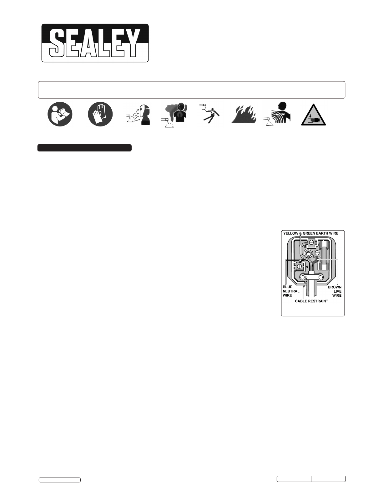
(UK only - see diagram).
Ensure the unit is correctly earthed via a three-pin plug (unless being connected to a 32A supply)
a) Connect the green/yellow earth wire to the earth terminal ‘E’.
b) Connect the brown live wire to live terminal ‘L’.
c) Connect the blue neutral wire to the neutral terminal ‘N’.
d) After wiring, check that there are no bare wires, that all wires have been connected
correctly, that the cable external insulation extends beyond the cable restraint and that the restraint is tight.
1.1.10. Cable extension reels. When a cable extension reel is used it should be fully unwound before connection. A cable reel with an RCD
fitted is recommended since any product which is plugged into the cable reel will be protected. The section of the cable on the cable reel
is important and should be at least 1.5mm², but to be absolutely sure that the capacity of the cable is suitable for this product and for
others that may be used in the other output sockets, we recommend the use of 2.5mm² section cable.
WARNING! Be very cautious if using a generator to power the welder. The generator must be self-regulating and stable with
regard to voltage, wave form and frequency. The output must be greater than the power consumption of the welder. If any of
these requirements is not met the electronics within the welder may be affected. NOTE: The use of an unregulated generator
may be dangerous and will invalidate the warranty on the welder.
WARNING! The welder may produce voltage surges in the mains supply which can damage other sensitive equipment
e.g. computers. To prevent this happening, it is recommended that the welder is connected to a power supply that does not feed any
sensitive equipment.
1.1.11. IMPORTANT! If using welder to full capacity, we recommend a 32A supply. We recommend you discuss the installation of a 32A
industrial round pin plug and socket with your electrician.
1.2. GENERAL SAFETY
DANGER! Unplug the welder from the mains power supply before performing maintenance or service.
Keep the welder and cables in good condition. Take immediate action to repair or replace damaged parts.
Use genuine parts and accessories only. Unapproved parts may be dangerous and will invalidate the warranty.
Use an air hose to regularly blow out any dirt from the liner and keep the welder clean for best and safest performance.
Check and spray the gas cup and contact tip regularly with anti-spatter spray, which is available from your Sealey dealer.
Locate the welder in a suitable work area. Ensure that the area has adequate ventilation as welding fumes are harmful.
Keep work area clean, tidy and free from unrelated materials. Also ensure that the work area has adequate lighting and that a fire
extinguisher is to hand.
WARNING! Use a welding head shield to protect eyes and avoid exposing skin to ultraviolet rays given off by electric arc.
Wear safety welding gauntlets.
Remove ill fitting clothing, remove ties, watches, rings and other loose jewellery and contain long hair.
RECOMMENDED
FUSE RATING:13A
© Jack Sealey Limited
Original Language Version
INSTRUCTIONS FOR:
MIG WELDER INVERTERS 160A,180A
MODEL NO’s: IMIG160, IMIG180
IMPORTANT: PLEASE READ THESE INSTRUCTIONS CAREFULLY. NOTE THE SAFE OPERATIONAL REQUIREMENTS, WARNINGS & CAUTIONS. USE THE PRODUCT
CORRECTLY AND WITH CARE FOR THE PURPOSE FOR WHICH IT IS INTENDED. FAILURE TO DO SO MAY CAUSE DAMAGE AND/OR PERSONAL INJURY AND WILL
INVALIDATE THE WARRANTY. KEEP THESE INSTRUCTIONS SAFE FOR FUTURE USE.
Thank you for purchasing a Sealey product. Manufactured to a high standard, this product will, if used according to these instructions
and maintained properly, give you years of trouble free performance.
1. SAFETY
IMIG160,IMIG180 Issue: 1 - 05/01/16
Refer to
Instruction
Manual
Wear
Protective
Gloves
Warning:
Arc Rays
Warning:
Fumes and
Gases
Warning:
Electric Shock
Warning:
Electric Shock
Warning:
Fire Hazard
Warning:
Magnetic
Fields
Warning:
Crushing of
Hands
Ensure that the workpiece is correctly secured before operating the welder.
WARNING! Use a welding head shield to protect eyes and avoid exposing skin to ultraviolet rays given off by electric arc.
Wear safety welding gauntlets.
Remove ill fitting clothing, remove ties, watches, rings and other loose jewellery and contain long hair.
Ensure that the workpiece is correctly secured before operating the welder.
Avoid unintentional contact with workpiece. Accidental or uncontrolled use of the torch may be dangerous and will wear the nozzle.
Keep unauthorised persons away from the work area. Any persons working within the area must wear protective head shield and gloves.
Operators must receive adequate training before using the welder.
Stand correctly, keeping a good footing and balance, and ensure that the floor is not slippery. Wear non-slip shoes.
Turn machine OFF when not in use.
DO NOT operate the welder if it or its cables are damaged and DO NOT attempt to fit any unapproved torch or other parts to the welder
unit.
DO NOT get welder wet or use in damp or wet locations or areas where there is condensation.
DANGER! DO NOT weld near flammable materials, solids, liquids, or gases, and DO NOT weld containers or pipes which
have held such products. Avoid operating on materials cleaned with chlorinated solvents or near such solvents.
DO NOT stand welder on a metal workbench, car bodywork or similar object.
DO NOT touch any live metal parts of the torch or electrode while the machine is switched on.
DO NOT pull the welder by the cable or the torch and DO NOT bend or strain cables. Protect cables from sharp or abrasive items and
DO NOT stand on them. Protect from heat. Long lengths of slack must be gathered and neatly coiled. DO NOT place cables where
they could endanger other people.
DO NOT touch the torch or workpiece immediately after welding as they will be very hot. Allow to cool.
DO NOT operate welder while under the influence of drugs, alcohol or intoxicating medication, or if tired.
When not in use store the welder in a safe, dry, childproof area.
1.3. GAS SAFETY
Store gas cylinders in a vertical position only and ensure that the storage area is correctly secured.
DO NOT store gas cylinders in areas where temperature exceeds 50°C. DO NOT use direct heat on a cylinder. Always keep gas
cylinders cool.
DO NOT attempt to repair or modify any part of a gas cylinder or valve and DO NOT puncture or damage a cylinder.
DO NOT obscure or remove any official cylinder labels. Always check the gas identity before use. Avoid getting gas cylinders oily or
greasy.
DO NOT lift a cylinder by the cap, guard or valve. Always keep caps and guards in place and close valve when not in use.
Manufactured with a pressed steel outer casing, these units are lighter than traditional models, with weights of up to only 15kg. Inverter welders
offer many advantages over the traditional transformer type, giving greater duty cycles and more power factor efficiency. Fan cooled DC power
supply, suitable to weld steel, stainless steel, copper, nickel, titanium and their alloys. Thermal overload protection which automatically switches
the welder off when it exceeds maximum temperature. Front panel includes dials for voltage output and wire speed with indicator lights for input
power and alarm status. Includes 1.8mtr MIG torch, 1.8mtr earth cable, gas hose, industrial regulator and 0.6, 0.8 and 0.9mm contact tips.
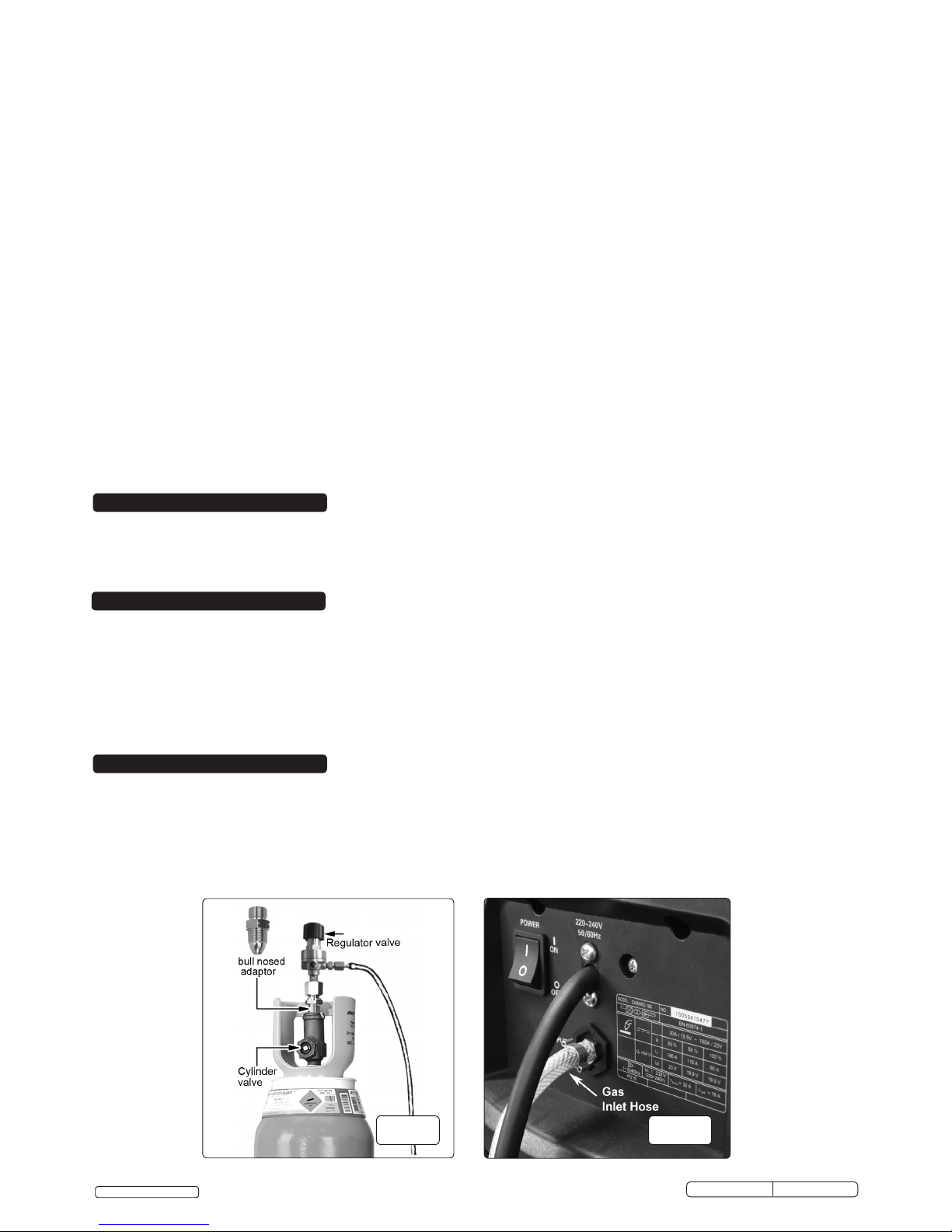
4.1. Connecting the gas cylinder
4.1.1. When using Argon or Argon mixtures, you will need to use the “bull nose adaptor”. Fit the bull nose adaptor to the cylinder with a spanner.
(If you intend to use CO² gas the regulator will fit directly onto the cylinder).
4.1.2. Fit the gas regulator on to the bull nose adaptor as shown in fig.1.
4.1.3. Push the clear gas tube provided (fig.1) onto the gas inlet nozzle and retain it with the wire clip provided. Push the other end of the tube
onto the gas outlet nozzle on the regulator and retain it with the other wire clip provided (fig.2)
4.1.4. When you are ready to weld set the regulator flow rate to 5-8 litres/min depending on the material to be welded, and whether there are
draughts which are strong enough to disturb the gas flow.
Model No: ...................... IMIG160 ............................................................IMIG180
Welding Current: .................30-160A .............................................................30-180A
Duty Cycle:......................30% @ 160A .....................................................25% @ 180A
Wire Capacity: ...................5kg .....................................................................5kg
Cooling System:..................Forced Air ..........................................................Forced Air
Gas Type:.......................CO², Argon, CO²/Argon Mix ...............................CO², Argon, CO²/Argon Mix
Torch: ..........................1.8mtr Non-Live .................................................1.8mtr Non-Live
Supply .........................230V ..................................................................230V
Weight:.........................12.5kg ............................................................... 12.5kg
2. INTRODUCTION
3. SPECIFICATION
4. SETTING UP
g.1 g.2
© Jack Sealey Limited
Original Language Version
IMIG160,IMIG180 Issue: 1 - 05/01/16
 Loading...