

Page 1

HVLP GraVity Feed toucH-uP SPray GunS
IMPORTANT: PLEASE READ THESE INSTRUCTIONS CAREFULLY. NOTE THE SAFE OPERATIONAL REQUIREMENTS, WARNINGS & CAUTIONS. USE
THE PRODUCT CORRECTLY AND WITH CARE FOR THE PURPOSE FOR WHICH IT IS INTENDED. FAILURE TO DO SO MAY CAUSE DAMAGE AND/OR
PERSONAL INJURY AND WILL INVALIDATE THE WARRANTY. KEEP THESE INSTRUCTIONS SAFE FOR FUTURE USE.
Model no: HVLP731, HVLP741.V2, HVLP742
thank you for purchasing a Sealey product. Manufactured to a high standard, this product will, if used according to these
instructions, and properly maintained, give you years of trouble free performance.
Refer to
instructions
Wear eye
protection
Wear respiratory
protection
1. SaFety
99 99 Familiarise yourself with the application, limitations and potential hazards peculiar to the spray gun.
9 99 WARNING!9disconnect the spray gun from the air supply before changing accessories, servicing or performing any maintenance.
99 99 Maintain the spray gun in good condition (use an authorised service agent).
99 99 Replace or repair damaged parts. Use authorised parts only. Unauthorised parts may be dangerous and will invalidate the warranty.
99 99 Keep the spray gun clean for best and safest performance.
99 99 ensure that the compressed air system can supply the spray gun air consumption for the model to be used.
99 99 Wear approved safety respiratory protection and safety eye goggles.
99 99 If spraying isocyanate based finisher, wear approved respirator/clean air breathing apparatus and cover exposed skin with latex gloves
and an impervious hooded coverall.
99 99 Remove ill-fitting clothing. Remove ties, watches, rings and other loose jewellery and tie back long hair.
99 99 locate the spray gun in a suitable work area. Keep area clean and tidy and free from unrelated materials and ensure that there is
adequate ventilation and lighting.
99 99 Keep children and unauthorised persons away from the work area.
99 99 When not in use, ensure that the air supply is turned off.
99 99 Avoid unintentional operation of spray gun.
99 99 The spray gun has been treated with an anti-corrosive agent at the factory and MUST be flushed out thoroughly with thinner before use.
98 99 do not point spray gun at yourself, other persons or animals.
98 99 do not direct air from the air hose at yourself, other persons or animals.
98 99 do not carry the spray gun by the hose, or yank the hose from the air supply.
98 99 do not exceed the working pressure of 43psi (3bar).
98 99 do not use the spray gun for any purpose other than that for which it is designed.
98 99 do not allow untrained persons to operate the spray gun.
98 99 do not get the spray gun wet or use in damp or wet locations or in areas where there is condensation.
98 99 do not operate the spray gun if any parts are missing or damaged as this may cause failure and/or personal injury.
99 99 When not in use, disconnect the spray gun from the air supply, clean thoroughly and store safely.
2. introduction
HVLP741.V2 / HVLP742
Gravity Feed Spray Guns
Round/flat fan control allows
the spray pattern to be adjusted
for any job.
The HVlP741.V2 Gravity Feed
Spray Gun has a brass air cap
with stainless steel needle and
nozzle make it suitable for
water-borne paint. Supplied
with a 1.3 set-up suitable for
topcoats. other set-ups are
available separately as shown
below.
The HVlP742 Gravity Feed
Spray Gun has an aluminium
air cap with stainless steel
needle and nozzle make it
suitable for water-borne paint.
Supplied with 2.0mm set-up
suitable for primer. other set-ups
are available separately as
shown below.
© Jack Sealey limited
Original Language Version
HVLP731 Gravity Feed
touch up Spray Gun
Ideal for blowing-in small
areas of panel where fine
control of paint and air is
necessary. Brass air cap with
stainless steel needle and
nozzle make it suitable for
water-borne paint. Supplied
with 0.8mm set-up, 1.0mm
set-up is available separately.
HVlP731, HVlP741.V2, HVlP742 Issue 4 (H) 02/05/18
Page 2

3. SPeciFication
Model no:.......................... HVLP741.V2 ...............HVLP742 .................HVLP731
Supplied standard set-up:. .................. 1.3mm ........................2.0mm .........................0.8mm
Available set-ups: ...........1.2, 1.4, 1.7, 2.0mm ................ 1.4, 1.7mm .........................1.0mm
Working pressure: .......................43psi (3bar) ............... 43psi (3bar) ..................43psi (3bar)
Air consumption: .............. 15.0cfm (425 l/min) ....15.0cfm (425 l/min) ........9.0cfm (255 I/min)
Pot capacity ...........................................600ml .........................600ml ...........................100ml
4. oPeration
4.1. air Supply
Recommended hook-up is shown in Fig.1.
4.1.1. ensure spray gun air valve (or trigger) is in the off position before connecting to the air supply.
4.1.2. You will require an air pressure of 43psi, and an air flow according to specification.
WarninG! ensure the air supply is clean and does not exceed 43psi while operating the spray gun. Too high an air pressure and/
or unclean air will shorten the product life due to excessive wear, and may be dangerous causing damage and/or personal injury.
4.1.3. drain the air tank daily. Water in the air line will ruin the paint finish and damage the spray gun.
4.1.4. Clean air inlet filter weekly.
4.1.5. line pressure should be increased to compensate for unusually long air hoses (over 8 metres). The minimum hose diameter should be
1/4” I.d. and fittings must have the same inside dimensions.
4.1.6. Keep hose away from heat, oil and sharp edges. Check hose for wear, and make certain that all connections are secure.
4.2. couplings
Vibration may cause failure if a quick change coupling is connected directly to the spray gun. To overcome this, connect a leader
hose to the spray gun. A quick change coupling may then be used to connect the leader hose to the air line recoil hose (Fig.1 and 2).
g.1
g.2
4.3. For best results, the gun should be held perpendicular to the surface being sprayed and moved parallel to it. Start the stroke before
squeezing the trigger and release the trigger before finishing the stroke. This will enable accurate control of the gun and material (Fig.3B).
4.4. Spray from a distance of about 6 to 10 inches (150 to 250mm) depending on the material and the atomizing pressure. The material
deposited should always be even and wet. each stroke must overlap the preceding stroke to obtain a uniform finish. To reduce
over-spray and obtain maximum efficiency, spray with the lowest possible atomizing air pressure.
4.5. Controlling the fan spray and the fluid.
a) Use the needle (paint) adjustment knob (Fig.4.2) to adjust the amount of paint flow.
b) The atomizing air flow is controlled by the control knob (Fig.4.1).
c) The volume of air input is controlled by the adjustment knob (Fig.4.3).
d) As width of spray is increased more material must pass through the gun to obtain the same coverage on the increased area.
e) Turn the air nozzle (Fig.4.4) to achieve a horizontal or vertical fan spray. lock the nozzle with retaining ring (Fig.4.5).
The spray pattern of the gun is variable from round to flat with all patterns in between. In normal operation, the wings on the
nozzle are horizontal (Fig.5). This provides a vertical fan-shaped pattern which gives maximum, uniform and even coverage when
moving the gun back and forth, parallel to the work surface (Fig.6).
g.5
g.3A
© Jack Sealey limited
g.3B
Original Language Version
g.6
g.4
HVlP731, HVlP741.V2, HVlP742 Issue 4 (H) 02/05/18
Page 3
5. Maintenance
For oPtiMuM PerForMance it iS Very iMPortant to enSure tHe SPray Gun iS correctLy cLeaned aFter eacH uSe.
disconnect from the air supply before attempting any cleaning or maintenance.
5.1. cleaning the gun
5.1.1. Flush the gun through with clean solvent.
5.1.2. Use a bristle brush and solvent to wash off accumulated paint.
5.1.3. Clean the air nozzle using a brush. Blow clean with air. Handle all nozzles carefully and do not make any alterations in the gun.
5.1.4. Wipe the outside of the gun with a dampened solvent rag.
5.1.5. If there is a need to probe the holes in the nozzles, ensure a tool that is softer than brass is utilised, under no circumstances use metal
tool, as the slightest amount of damage will adversely affect the spray pattern.
5.1.6. Adjust the fluid needle valve so that when the gun is triggered, air flow occurs before fluid flow.
5.2. Maintenance
Take care when re-assembling. Screw parts hand tight to avoid cross-threading. If a part cannot easily be turned by hand, check that it
is the correct part, or unscrew it, realign and retry. do not use excessive force when re-assembling.
5.2.1. When changing the nozzle size, ensure the complete nozzle set is fitted. This consists of air cap, fluid nozzle and paint needle. Insert the
fluid nozzle before paint needle.
6. trouBLeSHootinG
A faulty spray is usually caused by improper cleaning or dried material around the fluid nozzle tip or in the air nozzle. If cleaning is required,
remove these parts and soak them in solvent. T his will soften the dried material which can then be removed with a brush or a cloth.
These parts are carefully machined and any damage to them will cause a faulty spray. If either the air nozzle or fluid nozzle are damaged, they
must be replaced before a perfect spray can be obtained.
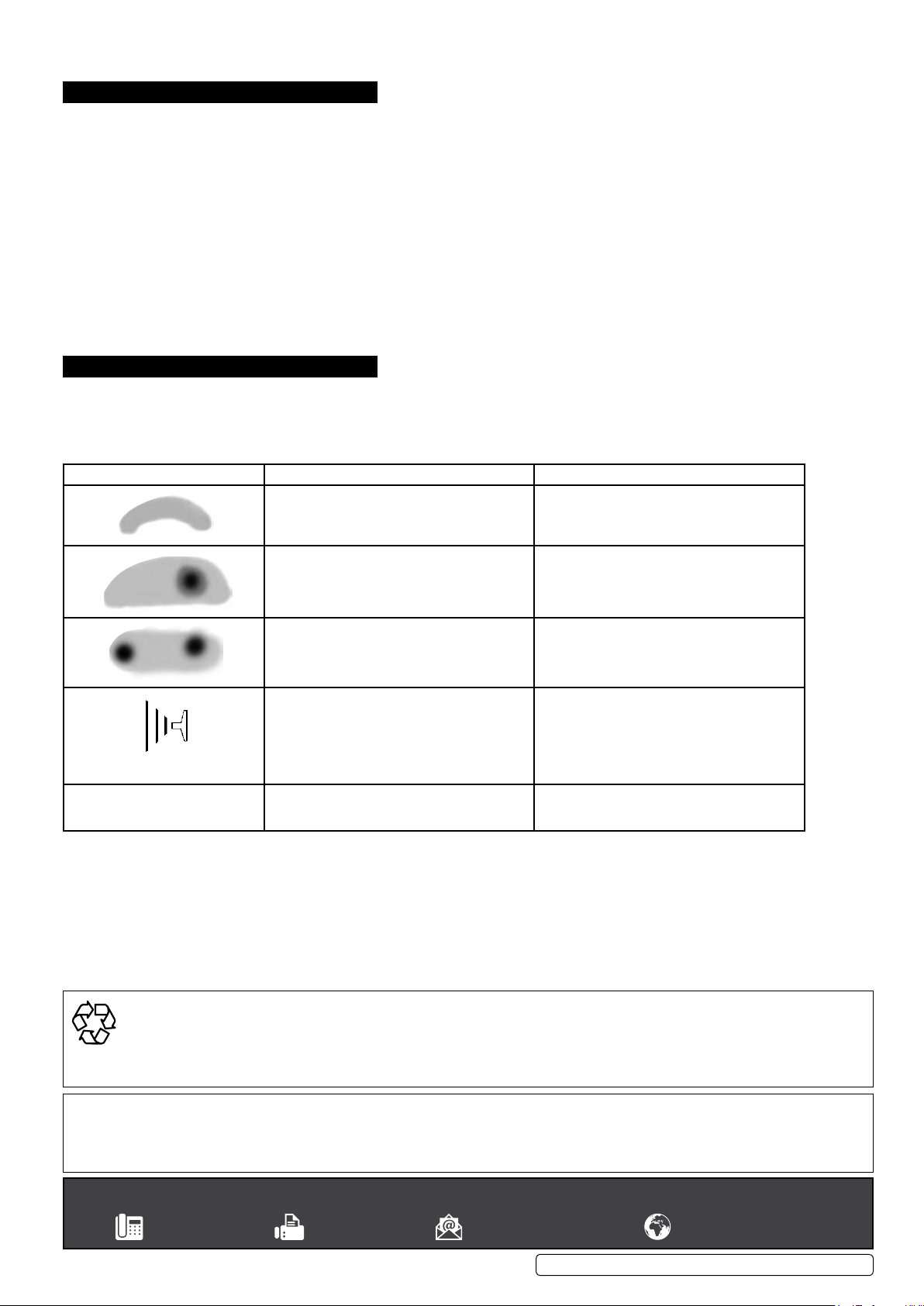
Problem Possible Causes Solution
Paint spray utter
Material bubbles or “boils” in paint cup.
dried material in a side port restricts passage of air.
Greater flow of air from the clean side port forces a
fan pattern in the direction of the clogged side.
dried material around the outside of the fluid nozzle
tip restricts the passage of atomizing air at one point
through the centre opening of the air nozzle and
results in the pattern shown. This pattern can also
be caused by a loose air nozzle.
Material too thin or atomization air pressure too high. Regulate material viscosity or reduce air pressure.
not enough paint in bottle.
nozzle set / seating dirty, damaged or loosely
installed.
Atomised air flowing through the paint channel to the
bottle. The paint nozzle is not sufficiently tight.
Air nozzle is not completely screwed on.
dissolve material in the side ports with solvent, then
blow the gun clean. do not poke into the nozzles
with metal instruments.
Remove the air nozzle and wipe off fluid tip using a
rag dampened with solvent. Tighten the air nozzle.
Refill bottle. Remove the fluid nozzle, clean the back
of the nozzle and the nozzle seat using a cloth
dampened with thinner. Refit the nozzle and secure
it tightly against the body.
If necessary replace nozzle set.
Tighten, clean or replace parts accordingly.
enVironMent Protection
Recycle unwanted materials instead of disposing of them as waste. All tools, accessories and packaging should be sorted, taken to
a recycling centre and disposed of in a manner which is compatible with the environment. When the product becomes completely
unserviceable and requires disposal, drain any fluids (if applicable) into approved containers and dispose of the product and fluids
according to local regulations.
note: It is our policy to continually improve products and as such we reserve the right to alter data, specifications and component parts without prior
notice.
important: no liability is accepted for incorrect use of this product.
Warranty: Guarantee is 12 months from purchase date, proof of which is required for any claim.
Sealey Group, Kempson Way, Suffolk Business Park, Bury St edmunds, Suffolk. iP32 7ar
01284 757500 01284 703534 sales@sealey.co.uk www.sealey.co.uk
© Jack Sealey limited
Original Language Version
HVlP731, HVlP741.V2, HVlP742 Issue 4 (H) 02/05/18
 Loading...