


HYDRAULIC PLATFORM TRUCKS
I
MPORTANT:
PLEASE READ THESE INSTRUCTIONS CAREFULLY. NOTE THE SAFE OPERATIONAL REQUIREMENTS, WARNINGS & CAUTIONS. USE
THE PRODUCT CORRECTLY AND WITH CARE FOR THE PURPOSE FOR WHICH IT IS INTENDED. FAILURE TO DO SO MAY CAUSE DAMAGE AND/OR
PERSONAL INJURY AND WILL INVALIDATE THE WARRANTY. KEEP THESE INSTRUCTIONS SAFE FOR FUTURE USE.
MODEL NO’S: HPT400H & HPT500.V2
Thank you for purchasing a Sealey product. Manufactured to a high standard, this product will, if used according to these instructions,
and properly maintained, give you years of trouble free performance.
Refer to
Instruction
manual
Wear safety
footwear
No reaching in
1. SAFETY
WARNING! Ensure all Health and Safety, local authority, and general workshop practice regulations and recommendations are strictly
adhered to when lifting or moving heavy loads. The lifting or movement of heavy loads may be dangerous if not undertaken correctly.
9 Familiarise yourself with the application and limitations, as well as the specific potential hazards peculiar to the truck.
9 Maintain the truck in good condition (use an authorised service agent).
9 Replace or repair damaged parts. Use genuine parts only. Non authorised parts may be dangerous and will invalidate the warranty.
9 Use a qualified person to lubricate and maintain the truck. DO NOT use brake fluid to top up hydraulic unit. Use Sealey hydraulic oil
only.
9 Keep the truck clean for best and safest performance. DO NOT use on tarmacadam when fully laden as the wheels may sink in.
9 Locate truck in an adequate working area for its function, keep area clean and tidy and free from unrelated materials.
WARNING! Use truck on flat, level, solid ground, preferably concrete. Ensure the floor over which the truck will be transported is swept
clean and that there are no obstacles in the way.
9 Keep the work area clean, uncluttered and ensure there is adequate lighting.
9 Keep children and non essential persons away from the loading/unloading and transporting area.
9 Keep hands and body clear of the edge and underside of the platform when operating the truck.
9 Maintain correct balance and footing. Ensure the floor is not slippery and wear non slip shoes.
WARNING! Ensure load is placed level and centrally on truck platform and if necessary strap load in place before attempting to lift,
lower, or transport. When raised, check that the platform will not foul on the handle and/or your hand when lowering the load.
WARNING! Use the truck with diligence. DO NOT allow truck to knock into anything. Even when unladen, the truck is heavy and if
misused could cause serious damage or personal injury. Continually monitor transportation, lifting and lowering operation.
9 Take care to ensure you can view the way ahead when moving the truck. Take special care when approaching blind corners.
9 Before lifting check that there are no overhead obstructions.
9 Engage the wheel locks before attempting to raise or lower the platform.
▲ DANGER! If a heavy load tips or leans STOP WHAT YOUR ARE DOING. MOVE QUICKLY TO A SAFE DISTANCE. DO NOT TRY
TO HOLD OR STEADY a heavy load. Failure to follow this instruction may cause serious personal injury.
9 Ensure the truck is fully lowered before attempting to transport a load.
9 Before lowering the platform, ensure there are no obstructions underneath the platform and that all persons are standing clear of the
truck.
9 The lowering speed is a fixed rate regardless of the load weight. Stop lowering by releasing the valve control lever on the handle.
WARNING! DO NOT exceed the rated capacity of the truck.
8 DO NOT use the truck if a part is missing or damaged.
8 DO NOT load the truck so that it is top-heavy. Ensure loads are evenly placed on the truck platform.
8 DO NOT ride on the truck or allow any person to be transported on the truck.
8 DO NOT use the truck for any purpose other than lifting, lowering and transporting loads.
8 DO NOT allow truck to free wheel in transit. Always propel and control the truck by using the handle.
8 DO NOT use the truck on sloping surfaces.
8 DO NOT operate the truck when you are tired or under the influence of alcohol, drugs or intoxicating medication.
8 DO NOT allow children to operate the truck.
8 DO NOT adjust or tamper with the hydraulic safety valve.
8 DO NOT place any part of your body within or under the truck platform when raised.
9 When not in use, fully lower the platform and store in a safe, dry, childproof area.
2. INTRODUCTION
Heavy-duty construction. All models fitted with two fixed and two swivel composite wheels for easy rolling over rough workshop and warehouse
floors. Swivel wheels fitted with foot-operated brake. One-piece hydraulic unit controlled by large rear mounted foot pedal. Safety release
mechanism positioned on handlebar for smooth controlled descent. Suitable for numerous garage, industrial and warehouse handling applications.
Supplied with non-slip platform cover for added load security. May also be used as a mobile service bench.
© Jack Sealey Limited
Original Language Version
HPT400H, HPT500.V2 Issue: 4(D) - 08/08/18
3. SPECIFICATION
Model HPT400H HPT500.V2
Capacity (kg) 400kg 500kg
Min platform height (mm) 360mm 280mm
Max platform height (mm) 1350mm 860mm
Platform length 910mm 815mm
Platform width (mm) 500mm 500mm
Wheel diameter 125mm 125mm
4. ASSEMBLY
4.1. A minimum of two people will be required to lift the truck out of its packaging. Alternatively, cut and fold down flat one end of the box and
wheel the truck out.
4.2. Fitting the handle.
4.2.1. At the back of the truck there are two upstanding sockets to receive the bent loop handle, fig.1D.
Partially unscrew the two locking bolts that pass into the sockets so that they no longer protrude into the sockets. Drop the ends of the
bent chrome handle into the sockets and tighten the bolts until the handle is held firmly.
4.2.2. Model HPT400H has a different handle fixing arrangement. The ends of the chrome handle have flanges which sit down onto flat
platforms at either side of the truck, see fig.5X. The handle is retained by two large socket cap bolts inserted from underneath. You will
require a 10mm Allen Key to tighten the bolts. Place a split washer followed by a plain washer over each bolt before inserting and
tightening.
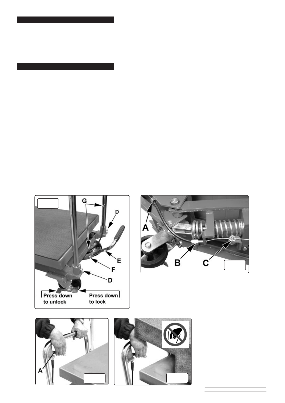
4.3. Fitting the foot pedal.
4.3.1. Slide the end of the foot pedal into the socket situated centrally between the two handle uprights, see fig.1E. On some models the
foot pedal retaining bolt, see fig.1F, screws directly into the material of the foot pedal stem. In this case place a split washer over the bolt
followed by a plain washer, before inserting the bolt. On other models the bolt passes directly through the stem and the socket and is
retained with a plain washer followed by a split washer followed by a nut. Ensure the fixing arrangement is tight enough to hold the pedal
firmly in place (do not over tighten).
4.4. Connecting the control cable.
4.4.1. Remove the cable guide bush, fig.2B, from the free end of the cable and feed the end of the cable and cable sheath through the cable
guide tubes welded to the handle and the underside of the frame. See fig.1G and fig.2A. The exact position and number of the guides
may vary from model to model. Once the cable has been fed through the guides slide the bush back over the cable and onto the sheath.
4.4.2. Feed the cable through the hole in the bush retaining bracket and then through the hole in the clamping bolt on the actuating lever, see
fig.2C. Now screw the guide bush into the bracket with a 12mm spanner, see fig.2B. Pull the end of the cable to so that there is no
play in the movement of the lever mounted on the handle. Hold the clamping bolt, fig.2C steady with a 12mm ring spanner and tighten the
nut on the other side of the lever with a 13mm ring spanner.
fig.1
fig.2
© Jack Sealey Limited
fig.3
Original Language Version
fig.4
HPT400H, HPT500.V2 Issue: 4(D) - 08/08/18
 Loading...