


INSTRUCTIONS FOR:
PORTABLE GENERATOR
Models:
HG50.25.V2, HG55.28.V2,HG65.30,HG90.44 & HG130.74.V2
Thank you for purchasing a Sealey product. Manufactured to a high standard this product will, if used according to these instructions
and properly maintained, give you years of trouble free performance.
IMPORTANT: PLEASE READ THESE INSTRUCTIONS CAREFULLY. NOTE THE SAFE OPERATIONAL REQUIREMENTS, WARNINGS AND
CAUTIONS. USE THIS PRODUCT CORRECTL
CAUSE DAMAGE AND/OR PERSONAL INJURY AND WILL INVALIDATE THE WARRANTY. PLEASE KEEP INSTRUCTIONS SAFE FOR FUTURE USE.
Y AND WITH CARE FOR THE PURPOSE FOR WHICH IT IS INTENDED. FAILURE TO DO SO MAY
1. SAFETY INSTRUCTIONS
p WARNING! Ensure any Health & Safety, Government, or local authority regulations are adhered to when using this equipment.
3 Familiarise yourself with the application and limitations, as well as the potential hazards, of the generator.
3 Maintain the generator in good condition (use an authorised service agent). Replace or repair damaged parts. Use genuine parts only.
Unauthorised parts may be dangerous and will invalidate the warranty.
3 This generator is designed and manufactured for specific applications. Do not attempt to modify the unit or use it for any application for
which it is not designed. If you have any questions regarding the application of the unit please contact your local Sealey dealer.
p WARNING! DO NOT exceed the Wattage/Amperage capacity of the generator. Add rated wattage of all devices intended for connection
at any one time, the total must not exceed rated wattage of generator (see specifications). In most cases the rated wattage of an electrical
device can be found on the nameplate. If the nameplate only gives voltage and amperage, multiply the two to give rated wattage (Volts x
Amps = Watts)
p
p
WARNING! Generator exhaust gases contain deadly carbon monoxide which must not be inhaled. Always allow sufficient ventilation.
p
p
WARNING! If you decide to use an Earth Leakage Circuit Breaker (also referred to as an RCD or Ground Fault Circuit Interrupter),
it is imperative that the neutral end of the power winding is connected to the frame of the generator set and that the earth lug on the
frame is connected with a low impedance connector to the local earth via an earth spike or local protective earth conductor. This
connection should only be attempted by a qualified electrician, after first having consulted your local dealer.
s
s
DANGER! This generator is designed for outdoor use only. To use the generator inside any building or enclosure, including the
generator compartment of a caravan, may result in fire or an explosion. No user performed modifications, including venting of
the exhaust and/or cooling ventilation, will eliminate the danger.
s
s
DANGER! If this unit is used for back-up power in the event of a commercial power failure, the following steps must be taken.
Before connecting the generator to the electrical system, open the main circuit breaker to isolate the generator and system from
the commercial electric supply. Failure to do this may result in damage to the generator and may result in serious injury or fatality,
due to a back-feed of electrical energy.
s
s
DANGER! The generator produces a very powerful voltage that can cause a severe electrical shock. Avoid contact with bare
wires, terminals etc. Never allow any unqualified person to operate or service the generator.
p
p
WARNING! Petrol is highly flammable and petrol vapour is explosive. Do not permit smoking, naked flames, sparks or heat in the
vicinity while handling petrol. Avoid spilling petrol onto a hot engine. Comply with all laws regulating storage and handling of fuels.
p
p
WARNING! NEVER refuel when the engine is running or when the engine is hot. Allow cool down time.
3 Operate the generator only on level surfaces (maximum allowable tilt is 10º) and where it will not be exposed to excessive mois tur e, dirt
or co rro siv e va pou rs or be in the proximity of combustible material (flammable liquids, solids or gases).
3 Remove ill fitting clothing, ties, watches, rings and other loose jewellery and contain long hair. Wear appropriate protective clothing.
3 Keep non-essential persons away from the working area.
p
p
ARNING! Never start or stop the generator while electrical loads are connected and switched on. Start the engine, let it
W
stabilise, then connect the electrical l
p
p
WARNING! Do not use worn, bare, frayed or otherwise damaged electrical cables with the generator. To do so may result in electric shock.
7 DO NOT use the generator for any purpose other than that for which it is designed.
7 DO NOT operate the generator if any parts are missing or damaged, as this may cause failure and/or personal injury.
7 DO NOT over-fill fuel tank. Always leave room for fuel to expand.
7 DO NOT operate in the rain.
s
s
DANGER! Do not tamper with the engine governed speed setting. Higher operating speeds are dangerous and increase the risk
of personal injury and/or equipment damage. The generator supplies the correct rated frequencies and voltage only when
running at the correct gover
Operating at excessively low speeds may result in shortened engine life. Over-speeding will invalidate the warranty.
7 DO NOT operate the generator when you are tired, under the influence of alcohol, drugs or intoxicating medication.
7 DO NOT store generator with fuel in tank where petrol vapours might reach an open flame or spark.
oad. To stop engine, disconnect the electrical load and let engine stabilise before switching off.
speed. Incorrect frequency and/or voltage can damage some connected electrical loads.
ned
2. INTRODUCTION & SPECIFICATIONS
2.1 These generators are powered by Honda OHC GC and OHV GX engines. The units offer a quiet and refined power delivery. In models
HG50.25 and HG55.28 the power units are coupled to dual voltage brushless alternators. Models HG65.30, HG90.44 and HG130.74 p ower
industrial quality alternators and are for industrial or arduous applications.
SPECIFICATIONS
Model No. HG50.25.V2 HG55.28.V2 HG65.30 HG90.44 HG130.74.V2
Power Unit: 5.0hp 5.5hp 6.5 9.0hp 13hp
Motor Type Honda GC160 Honda GX160 Honda GX200 Honda GX270 Honda GX390
Output: 230V/110V 50hz 230V/110V 50hz 230V/110V 50hz 230V/110V 50hz 230V/110V 50hz
Current Rating: 9.1A/19.0A 9.6A/20.0A 13.0A/27.3A 17.4A/36.4A 26.0A/54.5A
Continuous Power Rating: 2100W
Fuel Tank Capacity: 2.0l 3.6l 4.3l 6.0l 6.5l
Running time: 2.2h 3.1h 3.2h 3.2h 2.7h
Noise Rating: 98LWA 95LWA 98LWA 96LWA 99LWA
Dry Weight: 30kg 38kg 41kg 56kg 75kg
2200W
3000W
HG50.25.V2, HG55.28.V2, HG65.30, HG90.44, HG130.74.V2. - 3 - 030502
4000W
6000W
OPERATING INSTRUCTIONS
3.
pp
WARNING! Before use, ensure you read, understand and comply with the safety instructions in this document. Ens ure you
fully understand the application and limitations, as well as the potential hazards, of the generator.
pp
WARNING! Never connect the generating set earth lead to pipes. Pipes may carry inflammable substances such as gas or
domestic fuel and there is a risk of fire or explosion in the event of a short circuit.
pp
WARNING! Never run the engine without an air filter fitted.
pp
WARNING! If the generator is being used after storage of more than 30 days, remove the desicant bags from the alternator
and the plastic tape from the air inlet and outlet ports - see paragraph 5.7.
3.1. EARTHING
3.1.1. The generating set must be earthed every time it is used, to reduce the chance of electric shock. To do this, use a 12mm² copper
wire and bolt it to the generator chassis. At the other end, bolt it to an earthing rod of copper or brass which has been driven into the
ground. This earthing connection will also dissipate static electricity generated by the electrical equipment.
PRE START-UP OF THE GENERATOR
pp
WARNING! Check the engine oil level before each start-up. Only use an approved oil and NEVER operate the engine with insufficient oil.
3 Check the air filter elements to ensure they are clean and in good condition, clean or replace as necessary.
3.2. FILING WITH ENGINE OIL
3.2.1. Ensure the generator set is on a flat horizontal surface strong enough to prevent it from sinking.
3.2.2. Unscrew the oil filler cap and wipe the dipstick clean.
3.2.3. Insert the dipstick into the filler neck but DO NOT screw it in.
3.2.4. Remove the dipstick and check the level indicated. If the level is too low, top up to the top of the filler neck with the recommended oil.
3.2.5. Replace the dipstick and screw in the oil filler cap.
Note: OIL WARNING SYSTEM The oil warning system is designed to prevent any damage to the engine as a result of insufficient oil in the
lower sump. Before the oil level in the lower sump can fall below the safety limit, the oil warning system will automatically stop the
engine (the engine ON/OFF switch will remain in the ON position).
3.3. FILING WITH FUEL
WARNING! NEVER refuel when the engine is running or when the engine is hot. Allow cool down time.
p
p
p
p
WARNING! Petrol is highly flammable and petrol vapour is explosive.
pp
WARNING! Never use an oil/fuel mixture or any polluted fuel. Fuel substitutes are not recommended.
3.3.1. Ensure all electrical loads are disconnected.
3.3.2. Ensure the area around the fuel tank filler hole is clean.
3.3.3. Remove the fuel tank filler cap, check the level of the fuel and refill with the recommended fuel if necessary.
3.3.4. Do not over-fill the fuel tank, always leave room for the fuel to expand.
3.4. STARTING THE GENERATOR
p
p
WARNING! The output sockets will be live once the engine has started.
3.4.1. Ensure you have performed all actions in paragraphs 3.2. and 3.3. above.
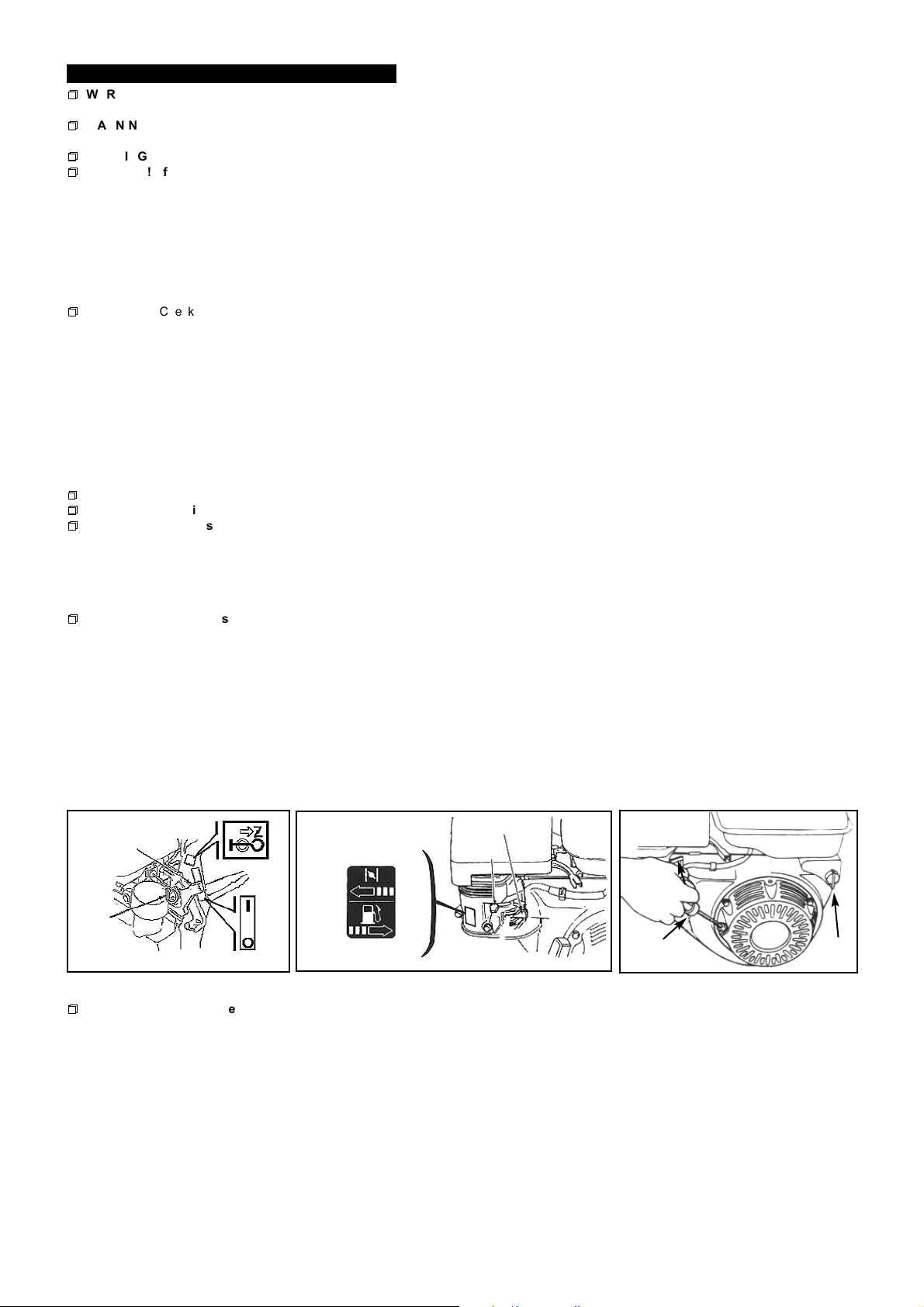
3.4.2. Turn the fuel valve to the ON position, fig.2. Not fitted to HG50.25.V2.
Note: If starting a warm engine or when the ambient temperature is high, move the choke control to the OPEN position.
3.4.3. Close the choke, figs.1 & 2.
3.4.4. Set the Engine Switch to the 1 position, figs.1 & 3.
Note: Ensure there is sufficient free area behind to prevent peronal injury when pulling the rope.
3.4.5. Grasp the recoil handle and pull rope slowly until some resistance is felt. Let rope rewind slowly, then pull with a rapid full arm
stroke. Let rope slowly return.
3.4.6. When engine starts, move choke lever to half choke position until engine runs smoothly and then to the OPEN position.
3.4.7. If engine fails to start, repeat the procedure from paragraph 3.4.5. If it still will not start, refer to Trouble-Shooting section. If necessary
contact your authorised Sealey service agent.
Fig.1.
ENGINE
SWITCH
CHOKE
ROD
HG50.25.V2,
CLOSED
Fig.2.
CLOSE
ON
OFF
OFF
HG55.28.V2, HG65.30, HG90.44, & HG130.74.V2.
OPEN
ON
FUEL VALVE
CHOKE LEVER
ON
Fig.3.
STARTER
GRIP
3.5. USING THE GENERATOR
p
p
WARNING!: Do not exceed the wattage capacity of the generator.
3.5.1. Allow the engine to warm up (approximately 3 minutes).
3.5.2. Select the required voltage output by positioning the voltage selector switch accordingly.
3.5.3. Connect the equipment to the generator socket.
3.5.4. Always observe the safety instructions of the equipment being used.
3.5.5. Carry out the following checks whilst the generator is in use:
Is there any vibration or abnormal noise?
Is there any backfiring or is the engine not running smoothly?
What colour is the exhaust gas? (Is it black or too white.)
3.5.6. If you notice any of the above points stop the generator (paragraph 3.6) and contact your local servicing agent.
3.6. TO STOP THE GENERATOR
3.6.1. Disconnect the electrical load.
3.6.2. Allow the engine to run unloaded for 1 - 2 mins.
3.6.3. Stop engine by moving the engine switch to the 0 position, figs 1 & 3.
3.6.4. Turn off the fuel valve, fig .2. Not fitted to HG50.25.V2.
HG50.25.V2, HG55.28.V2, HG65.30, HG90.44, HG130.74.V2. - 3 - 030502
0 1
ENGINE
SWITCH
 Loading...