

Page 1
INSTRUCTIONS FOR:
PNEUMATIC FILTER CRUSHER
MODEL NO: HFC08.V2
Thank you for purchasing a Sealey product. Manufactured to a high standard this product will, if used according to these instructions
and properly maintained, give you years of trouble free performance.
IMPORTANT: READ THESE INSTRUCTIONS CAREFULLY. NOTE THE SAFE OPERATIONAL REQUIREMENTS, WARNINGS AND CAUTIONS. USE
THIS FILTER CRUSHER CORRECTLY AND WITH CARE FOR THE PURPOSE FOR WHICH IT IS INTENDED. FAILURE TO DO SO MAY
CAUSE DAMAGE AND/OR PERSONAL INJURY AND WILL INVALIDATE THE WARRANTY. RETAIN THESE INSTRUCTIONS FOR FUTURE USE.
1. SAFETY INSTRUCTIONS
WARNING! Wear protective gloves and approved safety eye protection (standard spectacles are not adequate).
WARNING! Ensure Health & Safety, local authority, and general workshop practice regulations are adhered to when using this equipment.
DO NOT allow untrained persons to use the filter crusher.
DO NOT operate the filter crusher when you are tired or under the influence of alcohol, drugs or intoxicating medication.
DO NOT operate the filter crusher if parts are damaged or missing as this may cause failure and/or personal injury.
DO NOT use the filter crusher for a task it is not designed to perform.
DO NOT crush aerosol cans, cylinders of compressed gas, fuel filters or containers of flammable liquids or solvents.
DO NOT smoke when using crusher.
DO NOT modify the crusher or alter the operation in any way to circumvent the interlocking door mechanism.
Place oil filters into the crushing chamber open side down.
Maintain the filter crusher in good condition. Replace or repair damaged parts. Use genuine parts only. Unauthorised parts may be dangerous
and invalidate the warranty.
Familiarise yourself with the applications, limitations and potential hazards of the filter crusher.
Keep work area clean, uncluttered and ensure there is adequate lighting.
Maintain correct balance and footing. Ensure the floor is not slippery and wear non-slip shoes.
Keep the filter crusher clean for best and safest performance.
When not in use release pressure from the filter crusher.
Wear appropriate clothing such as overalls.
Keep untrained/unauthorised personnel away from filter crusher.
Clean up any spilled oil immediately so it will not cause a slipping hazard.
If the unit has to be re-sited it should be moved with the crushing module in the lowered position.
2. INTRODUCTION & SPECIFICATION
2.1 Introduction.
Reduce your waste disposal costs* - crushing filters minimises the volume of your hazardous waste. Air operated oil filter press with safety lock-out
device which prevents the door being opened during operation. Floor mounting unit with outlet for waste oil transfer.
* For disposal by volume customers.
2.2 Specification.
Max. Filter Capacity (H x D): ...................216mm x 152mm
External Dimensions (H x W x D): . . . . . . . . . . . . 880 x 550 x 335mm
Internal Dimensions (H x W x D). . . . . . . . . . . . . . . . . 280 x 190 x 190
Air Supply: ...................................... 100-190psi
Capacity: . . . . . . . . . . . . . . . . . . . . . . . . . . . . . . . . . . . . . . . . . . . .10ton
Pressing Time: ....................................... 30sec
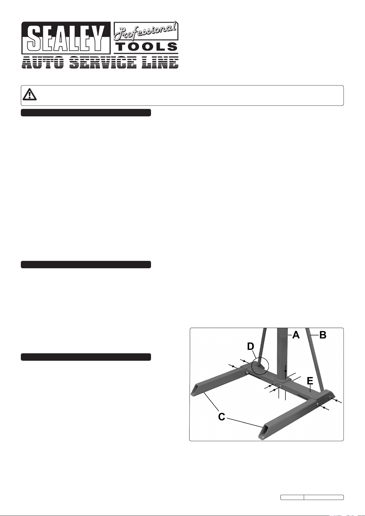
Fig.1
3. ASSEMBLY
WARNING! The unit is very heavy and should only be moved with a
crane or forklift truck.
3.1 Location and Assembly
Locate the crusher in a suitable place indoors on firm and level
concrete.
3.1.1 Firstly the stand must be assembled. Attach the two legs (Fig.1C) to
the cross beam (Fig.1E) using two bolts washers and nuts either side.
Ensure that upright supports (Fig.1B) are secured with the far nut
(Fig.1D) on each leg.
3.1.2 Place the upright on the crossbeam (Fig.1E) aligning with the
pre-drilled holes. Ensuring it is the correct way around with the lip over
the back of the cross beam. Secure with two bolts, washers and nuts
vertically through the cross beam and two horizontally through the lip
of the upright.
3.1.3 Secure the upright supports (Fig.1B) already attached to the legs (Fig.1D), to the upright using a bolt, nut and washer part way up the
upright (not in picture).
3.1.4 The unit must be bolted to the floor with four 1/2" anchor bolts, one at each end of the legs. This must be before the crushing unit is secured.
3.1.5 A fork lift truck or suitable crane should be used to raise the unit to its operational position. Remove the large nut and bolt from upper part of
the upright. Slide the mounting collars on the back of the crushing module onto the upright and align the holes in the upper collar with the
holes in the upright and insert the large bolt and secure with the nut provided.
3.1.6 The oil collection tray has a 1/2” hose adaptor on its underside so the unit can be plumbed into a remote waste oil container.
HFC08.V2 Issue: 1 - 25/06/09
Page 2
3.2. Air Supply.
Connect the air supply to the air inlet on the air regulatoe mounted on the
right hand side of the unit adjacent to the door handle. The inlet connection
is 1/4”FNPT.
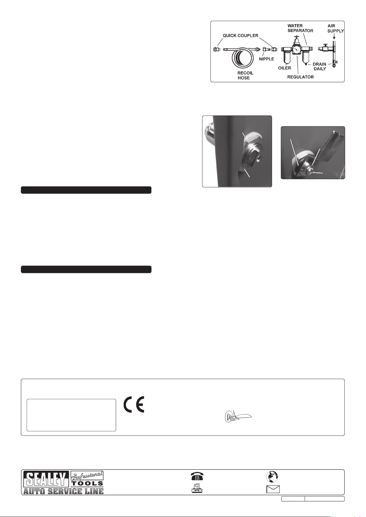
The recommended air hook-up procedure is shown in Fig.2
3.2.1 You will require a minimum air pressure of 100psi.
3.2.2 WARNING! Ensure the air supply is clean and does not exceed 190psi whilst
operating the filter crusher. Too high an air pressure and unclean air will
shorten the product life, and may be dangerous, causing damage and/or
personal injury.
3.2.3 Drain the air tank daily. Water in the air line will damage the ram.
3.2.4 Clean compressor air inlet filter weekly.
3.2.5 Line pressure should be increased to compensate for unusually long air hoses (over 8 metres).
3.2.6 Keep hose away from heat, oil and sharp edges. Check hose for wear, and make certain that all connections are secure.
Fig.2
3.3 Fitting Door Handle.
Place the handle shaft through the door from the outside and secure with
nylon washer and nut (Fig.3a).
Note: The door handle has a locking button and when fitting the handle it
should be configured so the locking button requires pressing to fully latch
or unlatch the door. The handle should be configured so the closed
(locked) position will leave the handle pointing downwards.
3.3.1 Move the handle to the horizontal (open) position. place the washer and
door catch on the end of the door handle shaft pointing downwards and
secure with the screw (Fig.3b).
Fig.3a
Fig.3b
Nylon Washer
Wave Washer
Domed Washer
Screw
Nut
4. OPERATION
4.1 Open air regulator and set pressure to a minimum of 100psi.
4.2 Place the empty filter, open end downwards in the centre of the crushing chamber.
4.3 Close the door ensuring the lock is full engaged. (The crusher will not function until the door is firmly closed).
4.4 Turn the control lever LEFT to the 'DOWN' position and the piston will descend.
4.5 When the crushing ram reaches the bottom the filter is crushed. You can also listen for the air to stop flowing (approx 30 seconds).
4.6 Turn the control lever RIGHT to the 'UP' position, when the piston has returned to the start position move the control lever back to the
centre 'STOP' position.
WARNING! Never attempt to open the door until the piston is fully retracted and the control lever is in the 'Stop' position.
4.7 Open the door and remove the crushed filter. Close air regulator and disconnect air supply.
Note: Leave the door ajar when not in use.
5. MAINTENANCE
WARNING! All inspection and maintenance procedures should be carried out with the air disconnected and the ram retracted.
5.1 Normal maintenance.
5.1.1 Persons using the crusher should be properly trained in its use including inspection of the unit prior to operation. If the operator is in any
doubt regarding the proper functioning or structural integrity of the unit it should not be used. Remove it from service immediately and
contact your local Sealey dealer.
5.1.2 If the unit is used daily it should be further inspected by a qualified person on a weekly basis.
5.1.3 If the unit is used intermittently it should be further inspected by a qualified person on a monthly basis.
5.1.4 All warning labels, instruction labels, and specification labels should be complete and readable.
5.1.5 External surfaces of the unit can be washed with a mild soap solution.
5.1.6 Clean and/or remove sludge and other foreign matter from the crushing chamber after each use.
Declaration of Conformity We, the sole importer into the UK, declare that the product listed below is in conformity with the
following standards and directives.
The construction file for this product is held by the Manufacturer and may be inspected, by a
Oil Filter Crusher
Model No. HFC08.V2
93/68/EEC CE Marking Directive
2006/42/EC Machinery Directive
NOTE: It is our policy to continually improve products and as such we reserve the right to alter data, specifications and component parts without prior notice.
IMPORTANT: No liability is accepted for incorrect use of this product.
WARRANTY: Guarantee is 12 months from purchase date, proof of which will be required for any claim.
INFORMATION: For a copy of our latest catalogue and promotions call us on 01284 757525 and leave your full name and address, including postcode.
Sole UK Distributor
Sealey Group,
Bury St. Edmunds, Suffolk.
national authority, upon request to Jack Sealey Ltd.
Signed by Mark Sweetman
For Jack Sealey Ltd. Sole importer into the UK of Sealey Professional Tools.
01284 757500
01284 703534
25th June 2009
www.sealey.co.uk
Web
email
HFC08.V2 Issue: 1 - 25/06/09
 Loading...