

Page 1

INSTRUCTIONS FOR:
HEADLAMP BEAM SETTER - COMPACT
MODEL NO: HBS2010.V2
Thank you for purchasing a Sealey product. Manufactured to a high standard, this product will, if used according to these instrutions,
and properly maintained, give you years of trouble free performance.
IMPORTANT: PLEASE READ THESE INSTRUCTIONS CAREFULLY. NOTE THE SAFE OPERATIONAL REQUIREMENTS, WARNINGS & CAUTIONS. USE THE PRODUCT
CORRECTLY AND WITH CARE FOR THE PURPOSE FOR WHICH IT IS INTENDED. FAILURE TO DO SO MAY CAUSE DAMAGE AND/OR PERSONAL INJURY AND WILL
INVALIDATE THE WARRANTY. KEEP THESE INSTRUCTIONS SAFE FOR FUTURE USE.
Refer to
instruction
manual
1. SAFETY
1.1. GENERAL SAFETY
WARNING! Ensure Health & Safety, local authority, and general workshop practice regulations are adhered to when using this equipment.
DO NOT use the Beam Setter in direct sunlight.
DO NOT splash the Beam Setter with water or any other liquid.
DO NOT operate the Beam Setter if it is damaged.
DO NOT use the Beam Setter for purposes other than that for which it is designed.
Avoid sudden changes in temperature.
Avoid sudden vibration.
Keep work area clean and tidy and free from unrelated materials.
Ensure the vehicle handbrake is engaged
Ensure there are no passengers in the vehicle.
When not in use store Beam Setter in a safe, dry, childproof location.
2. INTRODUCTION
Ideal for the garage or bodyshop where space is limited. Suitable for pre-MOT inspection and fulfils the legal obligation of the garage
or bodyshop to return vehicles to the customer in roadworthy condition. Compact design includes shortened mast and view through
aiming device. Suitable for all types of cars, motorcycles and light commercial vehicles (Classes I, II, III, IV, V, VII).
3. SPECIFICATION
Height: ..........1380mm
Width:............630mm
Length:...........550mm
IMPORTANT: This Beam Setter uses a fixed graduated screen in accordance with the requirements of the MOT regulations.
However it must be noted that the HBS2010.V2 is NOT approved by VOSA for conducting tests in accordance with MOT requirements.
4. ASSEMBLY
A Base
B Column
C Release Lever
D Light Box
E Aligner
F Retaining Handle
4.1. Attach the 3 wheels to the base (A) of the unit using long
bolts (axles), washers and nuts.
4.2. Attach base of column (B) to base of unit, using four sets
of bolts, washers and nuts. Column should be positioned so
that two holes in top of column base are in line with wheels.
4.3. Position mid section into column base and fix in place using
two countersunk headed allen bolts.
4.4. Slide the beam setting light box (D) over the top of the
column, squeezing the release lever (C) first. Release the
release lever to lock the light box onto the column.
4.5. Insert retaining handle (F) through top of column B, place a
washer then the aligner (E) onto the threaded end and
tighten.
© Jack Sealey Limited
Original Language Version
fig.1
HBS2010.V2 Issue: 2 - 07/01/16
Page 2
5.1. SET-UP
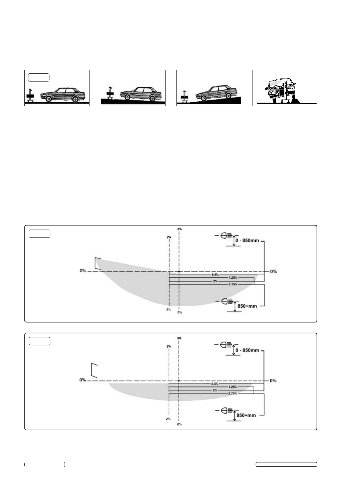
5.1.1. Position the vehicle on the designated headlamp aim standing area, when positioning the Beam Setter, ensure that the floor is even
and level, if this is not possible the vehicle and Beam Setter must be on the same slope, which must not exceed 3.0°. Headlights must
not be checked where surface angle exceeds 3.0° (fig.2).
5.1.2. Straighten the vehicle's wheels and check that the tyre pressures are correct.
5.1.3. Ensure the headlights are clean and dry.
5.1.4. If the vehicle is fitted with manual or electric headlamp levelling device, ensure that it is set for the vehicle with a normal load.
5.1.5. Remove anything which could alter the attitude of the vehicle, i.e. a heavy load in the boot.
fig.2
5.2. CHECKING BEAM SETTING
5.2.1. Position the Beam Setter approximately 200 to 500mm from one of the vehicle's headlamps.
5.2.2. Stand behind the Beam Setter and looking through the aligner, align with two symmetrical points on the vehicle i.e. the
bonnet lip or the bottom of the windscreen.
5.2.3. Ensure the line is parallel with the horizontal, or symmetrical selection, by rotating the Beam Setter. This will ensure that it is
square with the vehicle.
5.2.4. Measure the height of the centre of the headlamp from the floor.
5.2.5. Squeeze the release lever whilst supporting the light box and move the light box up or down the column as required until the centre
of the lens is at the same height as the headlamp. Release the release lever.
5.2.6. Use the white central sighting line on top of the light box housing to align the Beam Setter with the centre of the headlamp.
5.2.7. If necessary, start the vehicle's engine so that the battery is not drained during the procedure.
Note: When checking headlamp aim on vehicles with hydropneumatic suspension systems, it is necessary to have the engine
idling.
5.2.8. Switch the headlamps on to dip beam.
5.2.9. Determine the appropriate dip beam image and the aim (see figs.3 and 4). Headlamps of older vehicles (approx. pre 1950)
may have beam images which do not conform. In such cases check:
a) DIP BEAM headlamps are aimed so that they do not dazzle, i.e. the brightest part of the beam image is aimed at least 0.5%
below the horizontal (fig.5), or for headlamps which cannot be checked on dip beam, check:
b) MAIN BEAM headlamps are aimed so that the beam image centre is on or slightly below the horizontal (fig.5).
OK
3.0° MAX
NO
NO
ASYMMETRICAL DIPPED BEAM
fig.3
Correct projection on panel.
SYMMETRICAL DIPPED BEAM
fig.4
When testing symmetrical dipped beams, the
correct light projection on the plate should be
on the line 0.5%
5.2.10. Check that the headlamp beam tolerances are in accordance with the MOT inspection manual and are within the operating tolerances
specified by the manufacturer.
5.2.11. Adjust the headlight(s) until the required result is obtained.
5.2.12. When testing the more commonly used asymmetrical headlight (see fig.3), remember that the projection will light up a section on
the LEFT hand side of the plate at an angle of about 15° above the horizontal plane. Just under the centre, on the left, a small zone
© Jack Sealey Limited
Original Language Version
HBS2010.V2 Issue: 2 - 07/01/16
Page 3

will appear brighter than the rest of the projection.
5.2.13. Switch the headlamps on to main beam. They should be aimed so that the beam image centre is on the Zero position (fig.5). Adjust if
necessary.
MAIN BEAM
fig.5
There should be a strong, bright zone centred at
the zero position.
6. CALIBRATION
It is recommended that the unit has periodic calibration checks. The headlamp beam setter can be recalibrated using a laser alignment
calibration unit. We recommend the Sealey AK9999 (available from your authorised Sealey dealer).
Set up the laser calibration device and level it first, the beam setter can then be manoeuvred easily on it's stand with reference to the position
of the laser. The laser can be placed on any surface such as a car bonnet, box, table etc of suitable height.
Using the calibrated spirit level within the laser alignment calibration device, ensure that the unit is flat and level.
6.1.
6.2. Switch the laser on. Manoeuvre the beam setter in order to centre the laser beam in the beam setter lens. This must be done “by eye”.
There is a ±20mm tolerance on centralisation of the beam through the lens. The beam setter should be approximately 2m from the
laser.
6.3. The three dots projected onto the aiming screen should bisect the 0º line, at the far left, centre and far right of the screen (fig.6). It is
necessary at this point to rotate the column through the vertical axis, to track the beam from one side of the aiming screen to the other.
Take care to ensure that the laser and the beam setter both remain level throughout.
Alignment OK
Adjust screen
fig.6
6.4. If it is necessary to adjust the screen, unscrew the two retaining screws holding the top clear cover in place and remove it.
6.5. Slightly loosen the two screws holding the screen in place, reposition the screen so that the projected laser dots correctly bisect the 0º
line.
6.6. Retighten the screws, taking care not to move the screen out of position. Re-check to confirm it is still aligned correctly and then re-fit
the top cover and two screws.
7. MAINTENANCE
7.1. Clean with a slightly dampened cloth, being especially careful with the lens so as not to damage it.
7.2. DO NOT leave the machine in areas where corrosive vapour is present, i.e. from battery charging or paint spraying etc.
7.3. DO NOT oil the column.
When not in use store Beam Setter in a safe, dry, childproof location.
7.4.
Recycle unwanted materials instead of disposing of them as waste. All tools, accessories and packaging should be
sorted, taken to a recycling centre and disposed of in a manner which is compatible with the environment.
When the product becomes completely unserviceable and requires disposal, drain off any fluids (if applicable)
into approved containers and dispose of the product and the fluids according to local regulations.
Environmental Protection
Parts support is available for this product. To obtain a parts listing and/or diagram,
please log on to www.sealey.co.uk, email sales@sealey.co.uk or phone 01284 757500.
NOTE: It is our policy to continually improve products and as such we reserve the right to alter data, specifications and component parts without prior notice.
IMPORTANT: No liability is accepted for incorrect use of this product.
WARRANTY: Guarantee is 12 months from purchase date, proof of which will be required for any claim.
© Jack Sealey Limited
Sole UK Distributor, Sealey Group,
Kempson Way, Suffolk Business Park,
Bury St. Edmunds, Suffolk,
IP32 7AR
Original Language Version
01284 757500
01284 703534
www.sealey.co.uk
sales@sealey.co.uk
HBS2010.V2 Issue: 2 - 07/01/16
 Loading...