

Page 1
INSTRUCTIONS FOR:
BODYSHOP/WORKSHOP HEADLAMP
BEAM SETTER Model:
Thank you for purchasing a Sealey Product. Manufactured to a high standard this product will, if used according to these instructions and
properly maintained, give you years of trouble free performance.
IMPORTANT
PLEASE READ THESE INSTRUCTIONS CAREFULL
USE THIS PRODUCT CORRECTLY AND WITH CARE FOR THE PURPOSE FOR WHICH IT IS INTENDED. FAILURE TO DO SO MAY CAUSE
DAMAGE
GENERAL RULES
Read instruction manual carefully before using the headlamp beam setter (HBS).
TO AVOID DAMAGE ENSURE THE FOLLOWING ARE STRICTLY APPLIED.
DO NOT allow unqualified persons to operate the HBS.
DO NOT use the HBS in direct sunlight.
DO NOT splash the HBS with water or any other liquid.
DO ensure the work area is well ventilated.
AND/OR PERSONAL INJURY AND WILL INVALIDATE THE WARRANTY. PLEASE KEEP INSTRUCTIONS SAFE FOR FUTURE USE.
Y. NOTE THE SAFE OPERATIONAL REQUIREMENTS, WARNINGS AND CAUTIONS.
DO ensure that there is good lighting.
DO apply handbrake on vehicle.
DO avoid sudden changes in temperature.
DO avoid sudden vibration.
HBS2001
1. DESCRIPTION
The SEALEY BODYSHOP/WORKSHOP HEADLAMP BEAM SETTER, HBS2001, is supplied with a fixed column, mirror and visor. This
HEADLAMP BEAM SETTER may be used for checking headlights on cars, heavy goods vehicles and motorcycles.
SPECIFICATION: Height . . . . . . .1750mm Maximum height of beam measurement . . . . . . .1500mm
Width . . . . . . . . .620mm Minimum height of beam measurement . . . . . . . .220mm
Length . . . . . . . .660mm Focal length . . . . . . . . . . . . . . . . . . . . . . . . . . . . .500mm
2. ASSEMBLY
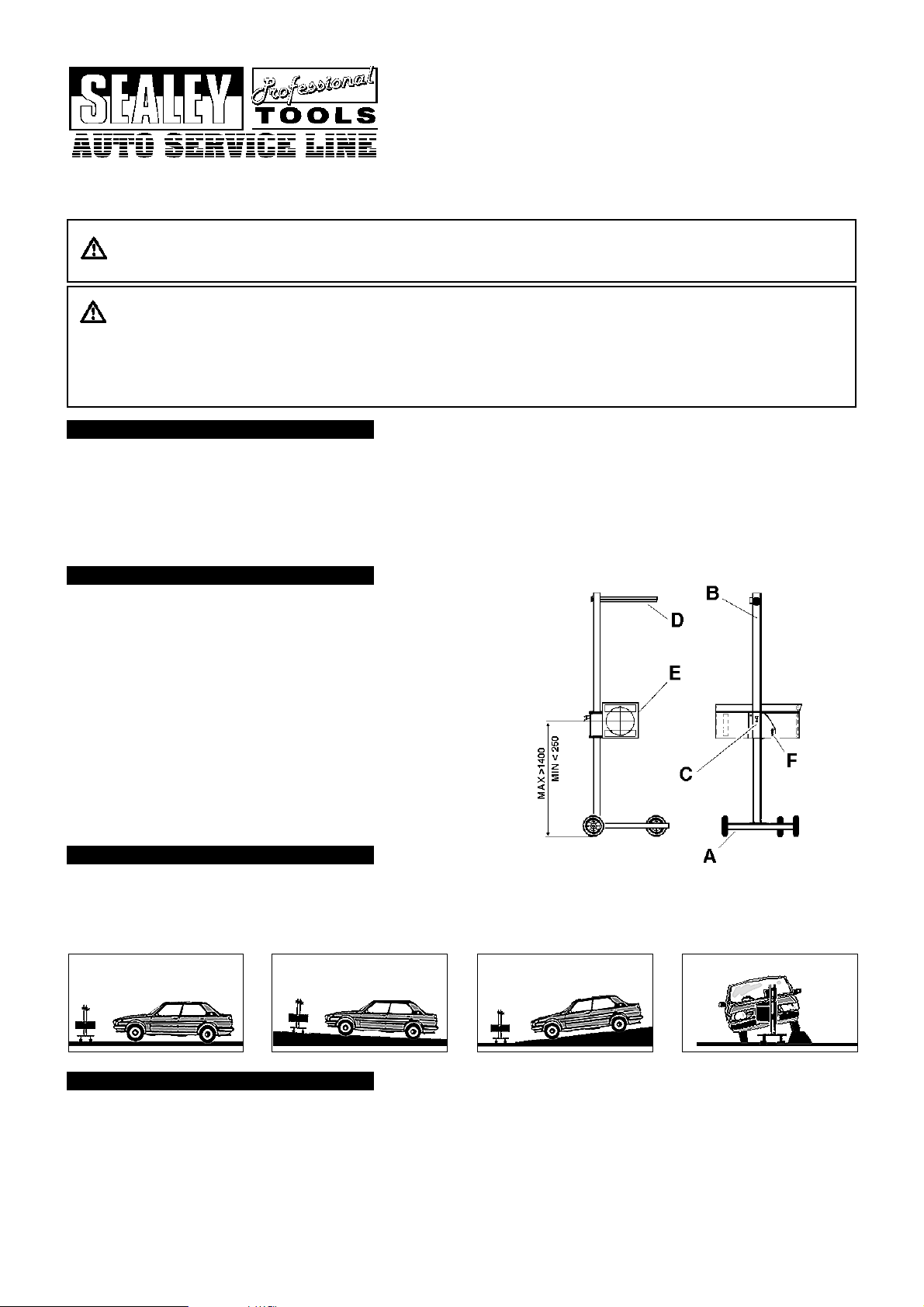
Refer to fig. 1
fig. 1
A BASE
B COLUMN
C VERTICAL SLIDING SYSTEM
2.1. Attach column B to base A using nuts, bolts and washers provided.
Column should be positioned so that optical system mounting plate on
sliding system C is facing the single wheel.
2.2. Attach mirror-visor D to mounting plate at the top of column B with the
two screws provided (in end of visor).
2.3. Fit the optical system E to the vertical sliding system C using the two
screws and washers provided (fit lever screw F and larger washer over
slotted hole).
D MIRROR-VISOR
E OPTICAL SYSTEM
F LEVER SCREW
3. WORKING SURFACE
Position the vehicle on the designated headlamp aim standing area.
3.1.
3.2. When positioning the HBS ensure the floor is perfectly even and level.
If this is not possible the vehicle and HBS must be on the same slope, which must not exceed 0.5º.
3.3.
3.4. Headlights must not be checked where surface angle exceeds 0.5º (see fig. 2).
fig. 2
OK
NO NO0.50 MAX
4. VEHICLE PREPARATION
4. 1. Straighten vehicle wheels.
4. 2. Check the tyre pressures.
4. 3. Ensure the headlights are clean and dry.
4. 4. If the vehicle is fitted with manual or electric headlamp levelling device, ensure this is set for vehicle with normal load.
4. 5. Remove anything which could alter the attitude of the vehicle, i.e. load, snow
, ice, mud, etc.
HBS2001 - 2 - 061103
Page 2
5. OPTICAL POSITIONING
5.1. Positioning
Locate the HBS approximately 200 to 500mm from the vehicle headlamp.
5.1.1. Standing behind the HBS, use the visor to align with a horizontal, or two symmetrical points on the vehicle i.e. the bonnet lip or the
bottom of the windscreen.
5.1.2. Ensure the visor line is parallel with the horizontal, or symmetrical selection, by rotating the HBS. This will ensure that the HBS is square
with the front of the vehicle.
5.1.3. Measure the height of the centre of the headlamp from the floor - say 650mm as an example.
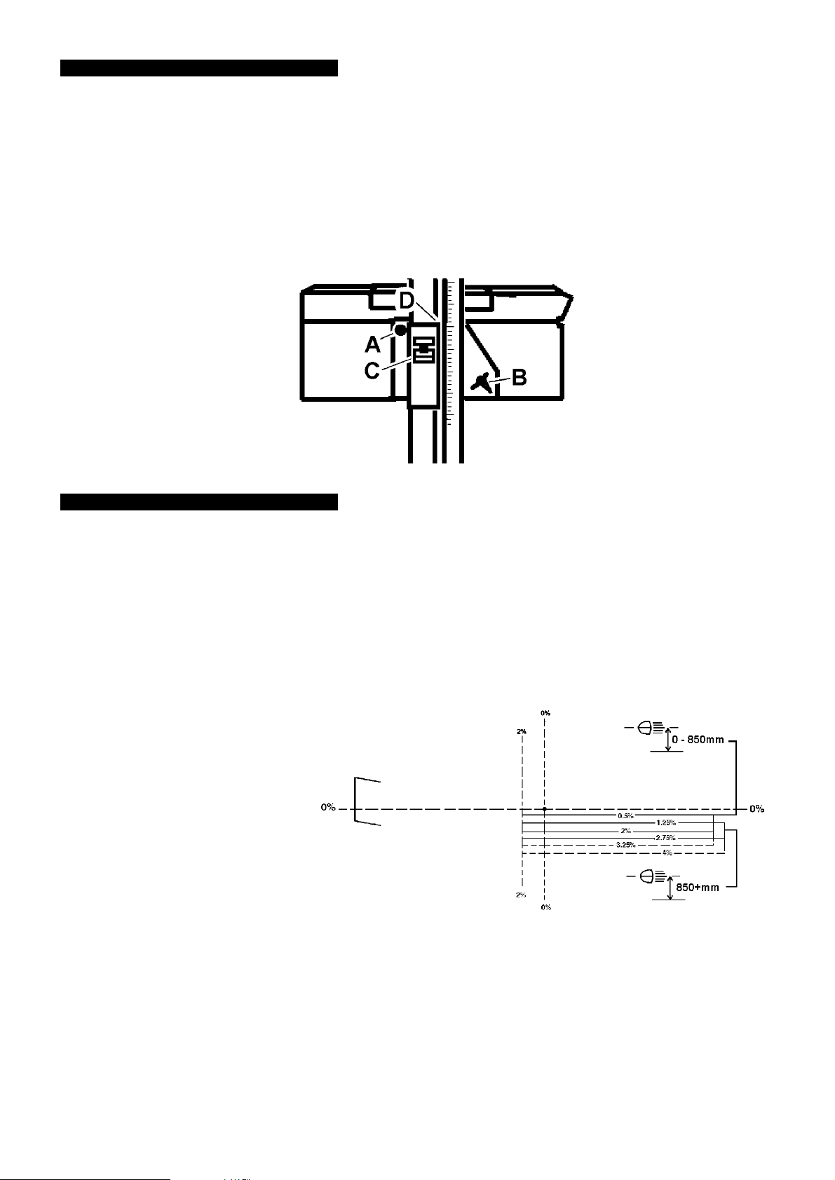
5.1.4. Squeeze the locking lever (fig. 3. C) on the vertical sliding system and move the system up or down the column until the top edge of the
slider (fig. 3.D) aligns with 65cm (650mm) on the column scale. Release locking lever. Centre of lens will now be at the same height
(650mm) as the centre of the headlamp.
5.1.5. Use the sighting line on the top of the optical system housing to horizontally align the HBS with the centre of the headlamp.
fig. 3
6. METHOD OF INSPECTION
6.1. Start engine, so that battery is not drained.
6.2. Align the HBS with the centre of the headlamp to be tested, as in Section 5.
6.4. With an assistant sitting in the driving seat, switch on the headlamp to the beam, dip or main, which is to be checked.
Note: When checking headlamp aim on vehicles with hydropneumatic suspension systems, it is necessary to have the engine idling.
6.5. Determine the appropriate dip beam image and the aim (see figs. 5 & 6). Headlamps of older vehicles (approx. pre 1950) may
have beam images which do not conform. In such cases check:
a) DIP BEAM headlamps are aimed so they do not dazzle, ie the brightest part of the beam image is aimed at least 0.5% below the
horizontal (fig. 5), or, for headlamps which cannot be checked on dip beam, check:
b) MAIN BEAM headlamps are aimed so that the beam image centre is on or slightly below the horizontal (fig. 7).
6.6. Graduated Screen
fig. 4
TANT
IMPOR
This HBS uses a fixed graduated screen in
accordance with the requirements of the MOT
regulations. However it must be noted that the
HBS2001 is not approved by the Vehicle
Inspectorate for conducting tests in accordance
with MOT requirements.
CORRECT
PROJECTION ON
LIGHT
THE LINE 0.5% (BEAM LIGHT)
6.7. Dipped Beam
6.7.1. Prepare the HBS and the car as previously instructed, then turn on the dipped beam.
Check that the headlamp beam tolerances are in accordance with the MOT
6.7.2.
specified by the manufacturer.
6.7.3. Adjust the headlight(s) until you obtain the required result.
6.7.4. When testing the more commonly used asymmetrical headlight (see fig. 5), remember that the projection will light up a section on
the LEFT hand side of the plate at an angle of about 15
appear brighter than the rest of the projection.
0
above the horizontal plane. Just under the centre, on the left, a small zone will
nspection manual and are within the operating tolerances
i
HBS2001 - 2 - 061
103
Page 3
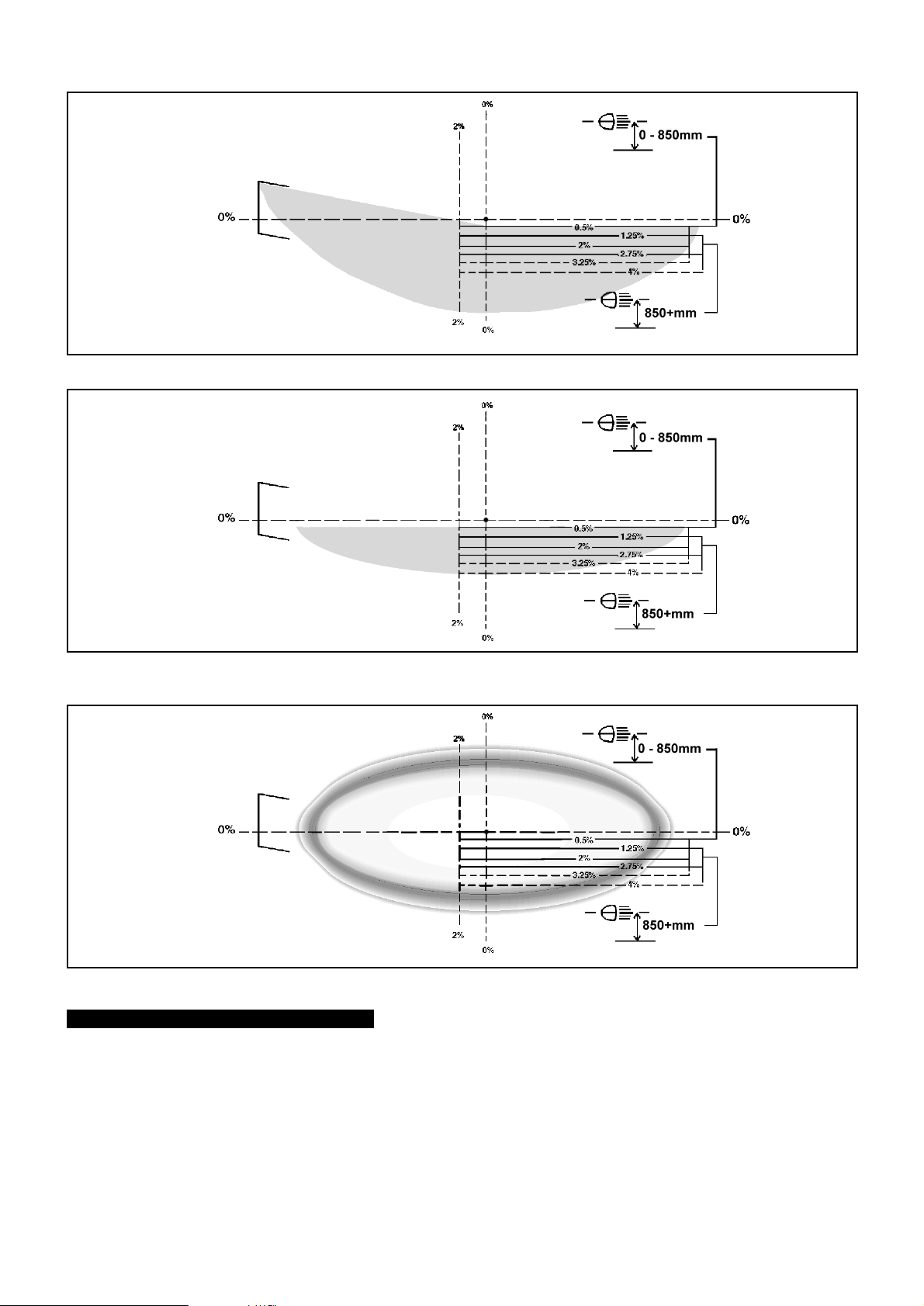
ASYMMETRICAL DIPPED BEAM
fig. 5
Correct projection on panel.
SYMMETRICAL DIPPED BEAM
fig. 6
When testing symmetrical dipped beams
the projection on the plate should be a
horizontal line.
MAIN BEAM
fig. 7
It is necessary to obt
centre of the plate, where the black spot is located.
7. THE LUXMETER
In addition to the numerically calibrated scales the luxmeter has a colour coded scale for main beam intensity which should be read as follows:
Main Beam
Indicator at RED/GREEN (BAD/GOOD) limit: Acceptable for vehicles travelling under 30mph (48km/h) and motorcycles.
1.
Indicator at the centre of GREEN (GOOD):
2.
3. Indicator on BLUE (HALOGEN): Acceptable for vehicles with halogen headlights.
ain a strong bright zone at the
Accept
able for vehicles travelling over 30mph (48km/h).
HBS2001 - 2 - 061
103
Page 4
8. CALIBRATION
We suggest that the unit has periodic calibration checks in situ. If the unit is covered by a service agreement with the MOT package installer,
they will carry this out on your behalf. You may however, wish to calibrate the unit yourself.
The headlamp beam setter can be recalibrated using a laser alignment calibration unit. We recommend the Sealey AK9999 (available from
your authorised Sealey dealer).
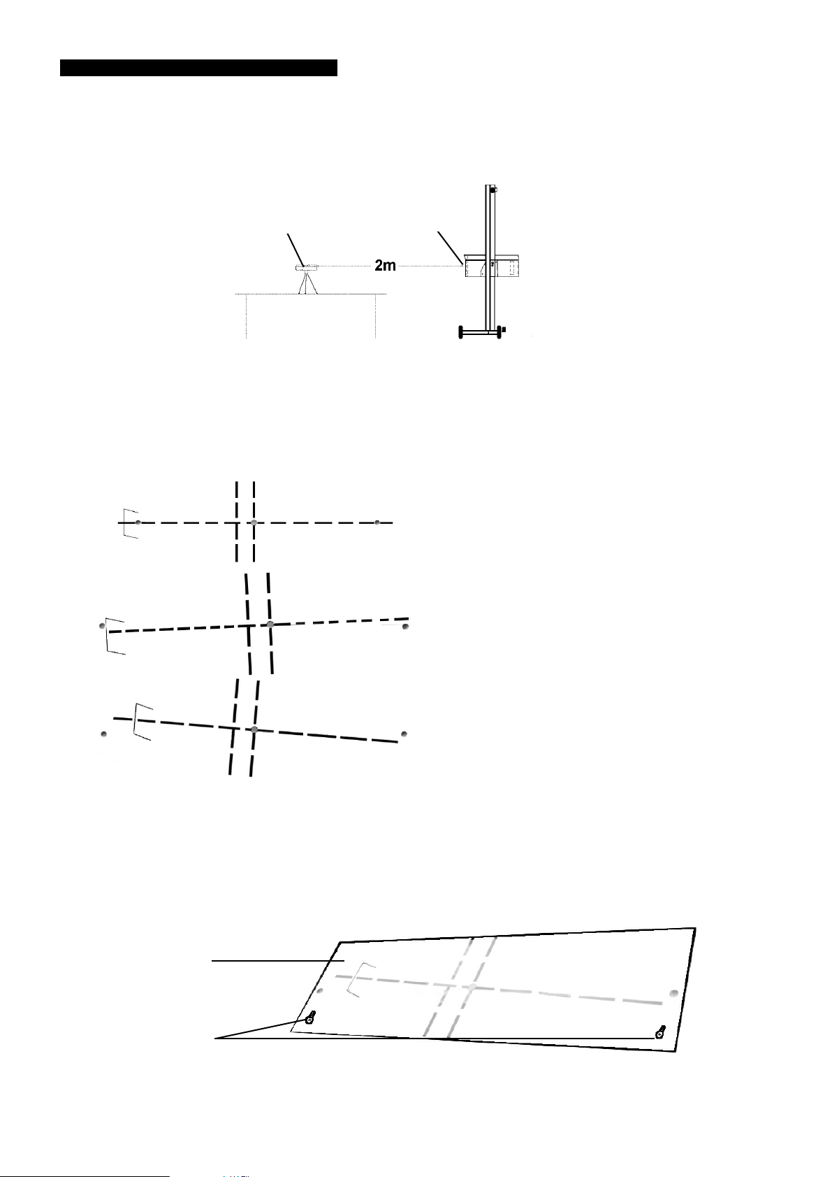
We recommend that the laser calibration device be set up and levelled first of all, the beam setter can then be manoeuvred easily on its stand
with reference to the position of the laser. The laser can be placed on any surface such as a car bonnet, box, table etc of suitable height.
Laser device
8.1 Using the calibrated spirit level within the laser alignment calibration device, ensure that the unit is flat and level.
8.2 Switch the laser on. Manoeuvre the beam setter in order to centre the laser beam in the beam setter lens. This must be done by eye.
There is a ±20mm tolerance on centralisation of the beam through the lens. The beam setter should be approximately 2m from the
laser.
8.3 The dot projected onto the aiming screen should bisect the 0º line, at the far left, centre and far right of the screen. It is necessary at
this point to rotate the column through the vertical axis, to track the beam from one side of the aiming screen to the other. Take care to
ensure that the laser and the beam setter box (see Section 9) remain level throughout.
Beam setter lens
Alignment OK
Adjust screen
Adjust screen
To adjust the aiming screen, use the two holding screws.
8.4
8.4.1 Loosen the screws and reposition the screen, so that the projected laser dot correctly bisects the 0º line.
8.4.2 Retighten the screws, taking care not to move the screen back out of position.
Aiming screen
Holding screws
HBS2001 - 2 - 061
103
Page 5

9. OTHER INFORMATION
The Headlamp Beam Setter is equipped with a spirit level located on the base of the optical box, which is visible through the transparent panel.
To level the box, loosen screws (fig.3.A & B) located on the side of the box and adjust the box until the spirit level registers horizontal. Re-tighten
the screws. The box level must be checked every time it is used on a different working surface.
10. CARE OF THE BEAM SETTER
10.1. The paint work is detergent resistant. Clean with a damp cloth, removing any stains. A small amount of alcohol may be applied to
stubborn areas of grime.
10.2. DO NOT leave the machine in areas where corrosive vapour is present, i.e. from battery charging or paint spraying etc.
10.3. DO NOT oil the column.
10.4. An optical box dust cover is available upon request.
NOTE: It is our policy to continually improve product
IMPORTANT: No liability is accepted for incorrect use of the product.
ARRANTY
W
INFORMATION: For a copy of our latest catalogue and promotions call us on 01284 757525 and leave your full name and address, including postcode.
:
Guarantee is 12 months from purchase date, proof of which will be required for any claim.
s and as such we reserve the right to alter data, specifications and component parts without prior notice.
Sole UK Distributor,
Sealey Group,
Bury St. Edmunds, Suffolk.
01284 757500
01284 703534
e-mail
www.sealey.co.uk
b
e
W
HBS2001 - 2 - 061
103
Page 6
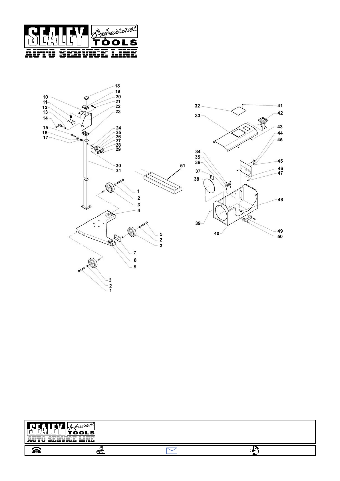
PARTS LIST FOR:
BODYSHOP/WORKSHOP HEADLAMP
BEAM SETTER Model:
HBS2001
Date: 060405
Issue: 3
Item Part No. Description
1 TCNA2010011 Screw
2 TCNC0010005 Washer
3
4 TCNB1010006 Nut
5 TCNA2010002 Screw
6
7 TC020010091 Flat
8
9 TCNA0010025 Screw
10 TCNA4010005 Screw
1
1
12 TC025010135 Lever
13 TCNC0010005 Washer
14
15 TCNA2010034 Screw
16
17 TC025020009 Spring
18 TCNR5020046 Plug
19 TC025010130 Sliding block
20 TCNA2010013 Screw
21 TCNC0010005 Washer
22
23 TC025010130 Sliding block
24
01284 757500
TCNR0010011 Wheel
TCNA2010005 Screw
TC020010001 Triangular base
Spring
TC02601001
TCNR5020009 Lever
TC0250101
TC025010005 Vertical slipping
TC025010123
1
19 Washer
asher
W
Sole UK Distributor,
Sealey Group,
Bury St. Edmunds, Suffolk.
01284 703534
Item Part No. Description
25 TC025010121 Rectangular sleeve
26 TCNA3010005 Dowel
27 TCNB0010008 Nut
28 TC025010122 Frontal flat
29 TCNA0010033 Screw
30 TCNA0010015 Screw
31 TC020010092 Column
32 TC020310007 Plexiglass cover
33 TC022010115 Cover
34 TCNB0010005 Nut
35 TC020010038 Level
36 TC020010037 Nut for level
37 TC020010238 Plate
38 TC025030014 Lens
39 TCNA4010008 Screw
40 TC022010113 Optics box
41 TCNA4010030 Screw
42 TC020020053 Luxmeter
43 TCNA4010006 Screw
44 TC020030036 Wiring harness
45 TCNB0010004 Nut
46 TC027010037 Control pannel
47 TCNA1010005 Screw
48 TCNB1010003 Nut
49 TC025030011 Handle
50 TCNA0010009 Screw
51 TC025020011 Mirror visor
e-mail
www.sealey.co.uk
b
e
W
 Loading...