


INSTRUCTIONS FOR: GALVANIZED STEEL SHED 3000 x 3000 x 2000mm MODEL No's: GSS3030.V2,GSS3030G.V2
Thank you for purchasing a Sealey product. Manufactured to a high standard, this product will, if used according to these instructions and maintained properly, give you years of trouble free performance.
IMPORTANT: PLEASE READ THESE INSTRUCTIONS CAREFULLY. NOTE THE SAFE OPERATIONAL REQUIREMENTS, WARNINGS & CAUTIONS. USE THE PRODUCT CORRECTLY AND WITH CARE FOR THE PURPOSE FOR WHICH IT IS INTENDED. FAILURE TO DO SO MAY CAUSE DAMAGE AND/OR PERSONAL INJURY AND WILL INVALIDATE THE WARRANTY. KEEP THESE INSTRUCTIONS SAFE FOR FUTURE USE.


Manual Gloves
1. SAFETY
- WARNING! Ensure Health & Safety, local authority, and general workshop practice regulations are adhered to when building this shed.
- ✓ Keep the work area clean, uncluttered and ensure there is adequate lighting.
- ✓ Keep children and unauthorised persons away from the working area.
- X DO NOT use the shed for any purpose other than that for which it is designed.
- ✓ Use appropriate safety clothing including eve protection.
Note! The assembly of this product will require assistance.
2. INTRODUCTION
Galvanized steel panels easily assembled to form a rigid and secure apex roofed shed. Model No. GSS2323G has single door and Model No. GSS3030G has double doors, which are secured by cross bolt and eyelet that accepts a padlock (not included) for additional security. All models supplied with bolt-down fixing kits and are available in silver or green.
| 3. SPECIFICATION | ||
|---|---|---|
| Model no: | GSS3030G.V2 | |
| Colour: | Silver | Greer |
| Roof: | Apex | Ape> |
| Doors: | 2 | |
| Overall Size (W x D x H*) | 3000 x 3000 x 2000mm | 3000 x 3000 x 2000mm |
| *Minimum Wall Height: |

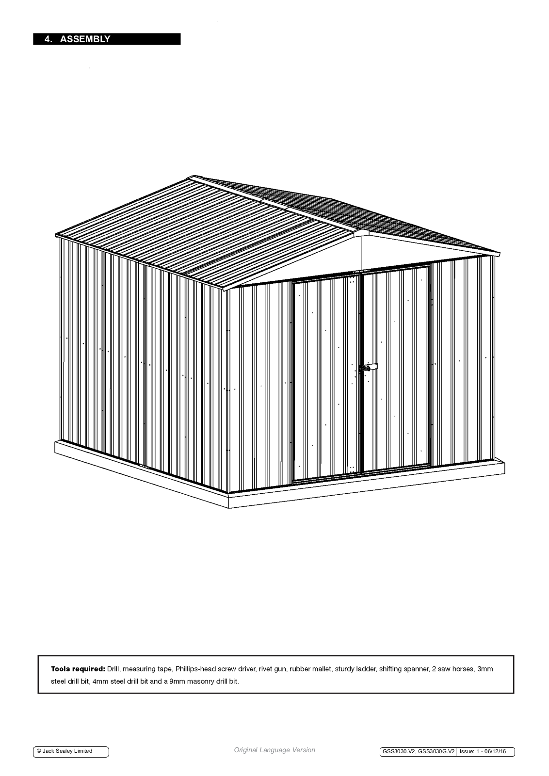
Tools required: Drill, measuring tape, Phillips-head screw driver, rivet gun, rubber mallet, sturdy ladder, shifting spanner, 2 saw horses, 3mm steel drill bit, 4mm steel drill bit and a 9mm masonry drill bit.
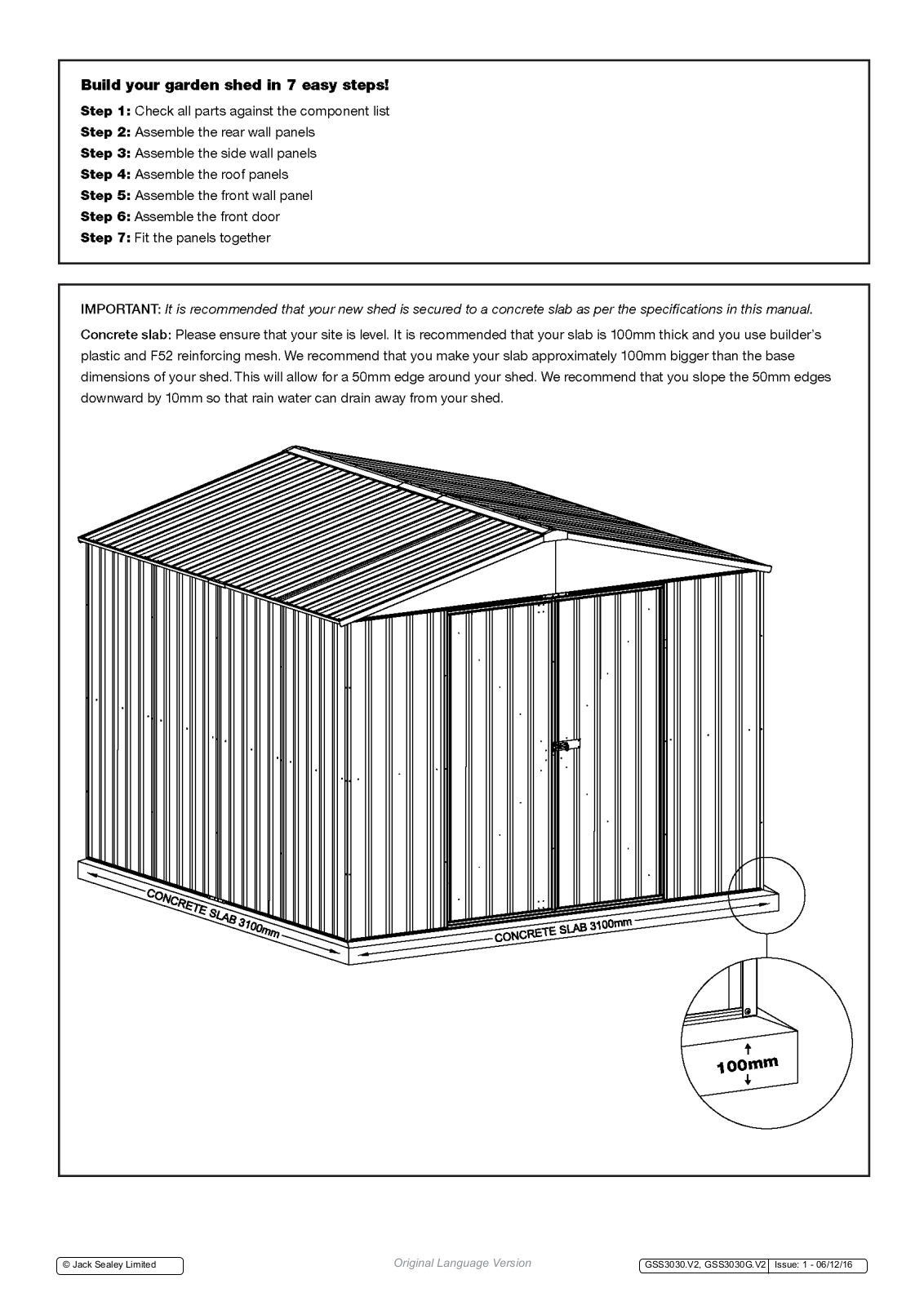
Build your garden shed in 7 easy steps!
Step 1: Check all parts against the component list
- Step 2: Assemble the rear wall panels
- Step 3: Assemble the side wall panels
- Step 4: Assemble the roof panels
- Step 5: Assemble the front wall panel
- Step 6: Assemble the front door
- Step 7: Fit the panels together
IMPORTANT: It is recommended that your new shed is secured to a concrete slab as per the specifications in this manual.
Concrete slab: Please ensure that your site is level. It is recommended that your slab is 100mm thick and you use builder's plastic and F52 reinforcing mesh. We recommend that you make your slab approximately 100mm bigger than the base dimensions of your shed. This will allow for a 50mm edge around your shed. We recommend that you slope the 50mm edges downward by 10mm so that rain water can drain away from your shed.

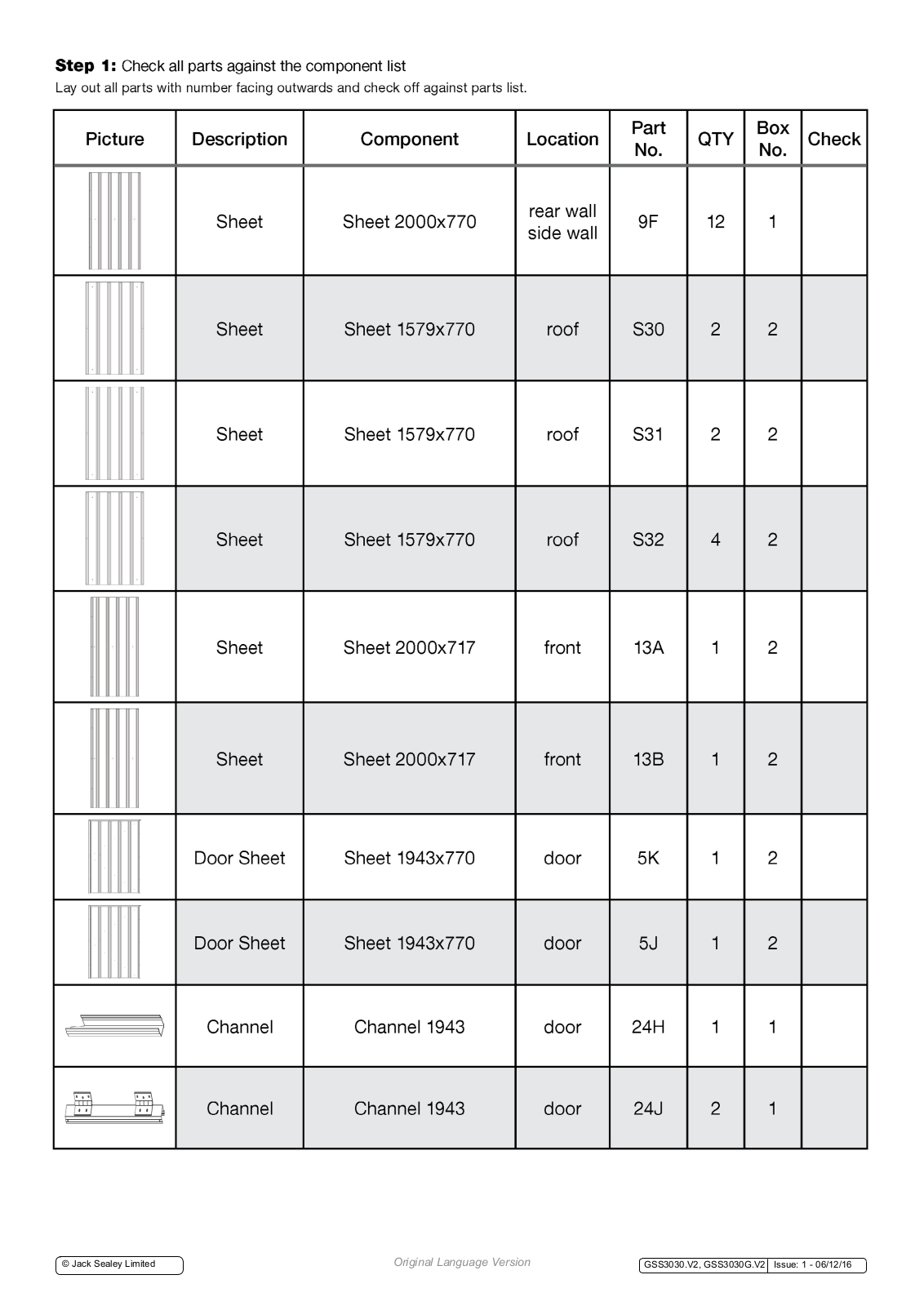
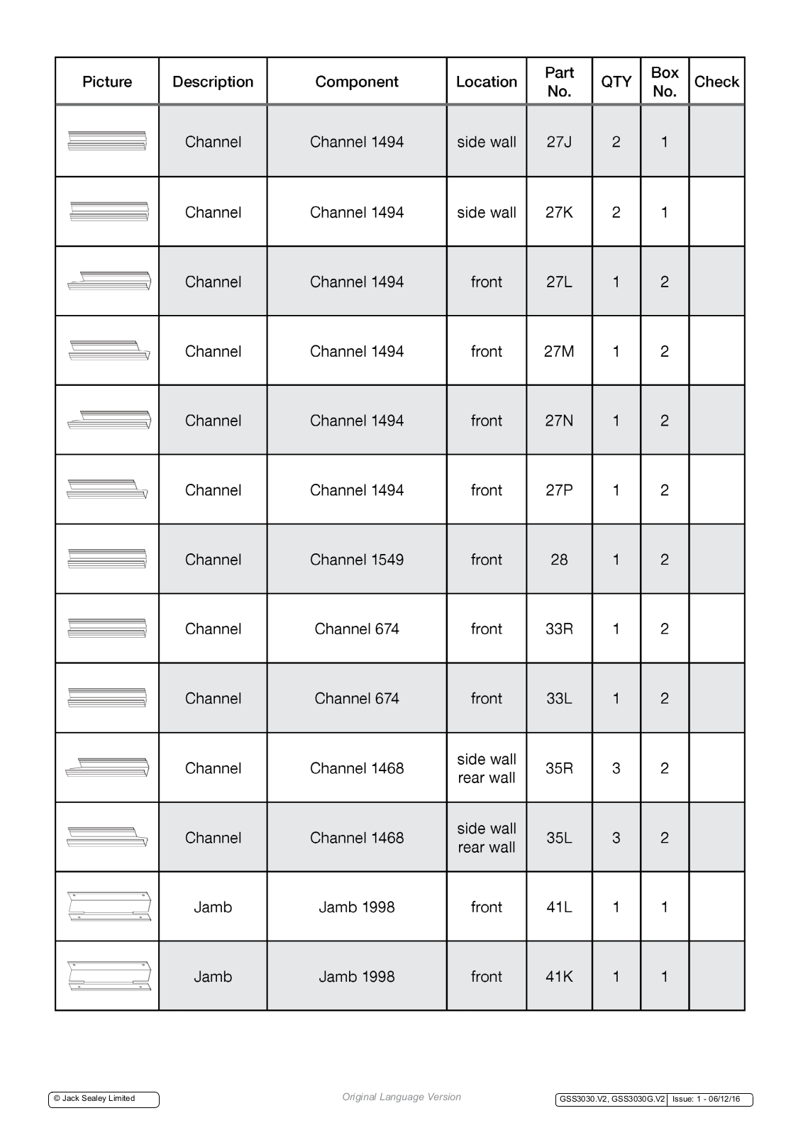
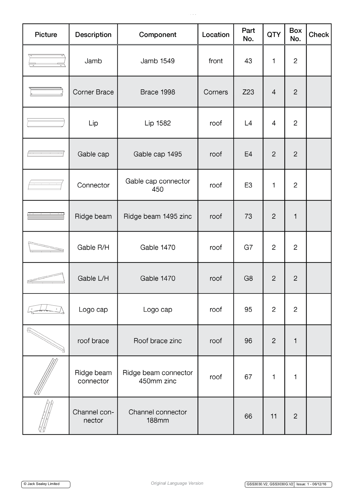
Step 1: Check all parts against the component list
Lay out all parts with number facing outwards and check off against parts list.
| Picture | Description | Component | Location |
Part
No. |
QTY |
Box
No. |
Check |
|---|---|---|---|---|---|---|---|
| Sheet | Sheet 2000x770 |
rear wall
side wall |
9F | 12 | 1 | ||
| Sheet | Sheet 1579x770 | roof | S30 | 2 | 2 | ||
| Sheet | Sheet 1579x770 | roof | S31 | 2 | 2 | ||
| Sheet | Sheet 1579x770 | roof | S32 | 4 | 2 | ||
| Sheet | Sheet 2000x717 | front | 13A | 1 | 2 | ||
| Sheet | Sheet 2000x717 | front | 13B | 1 | 2 | ||
| Door Sheet | Sheet 1943x770 | door | 5K | 1 | 2 | ||
| Door Sheet | Sheet 1943x770 | door | 5J | 1 | 2 | ||
| Channel | Channel 1943 | door | 24H | 1 | 1 | ||
| Channel | Channel 1943 | door | 24J | 2 | 1 |
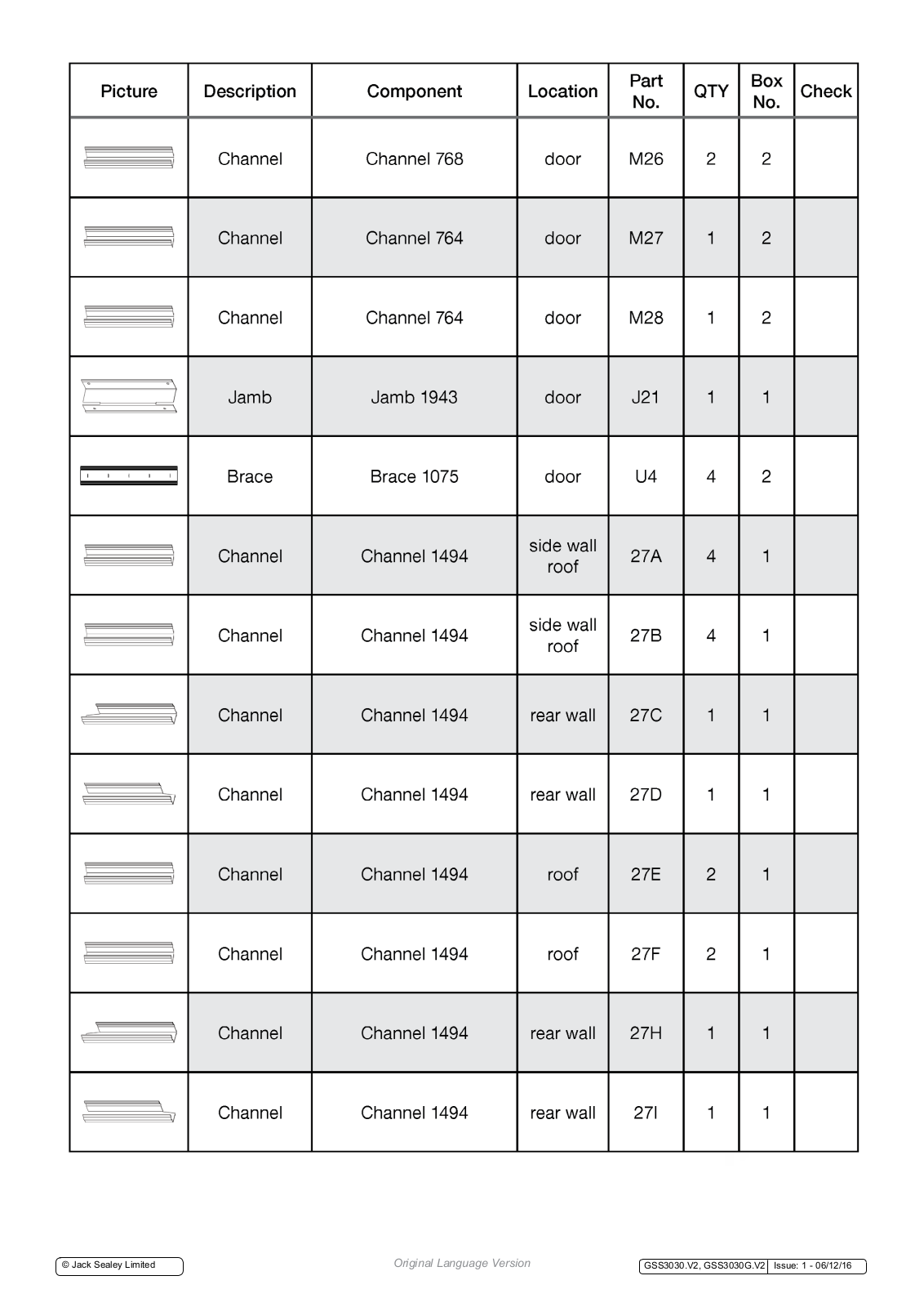
| Picture | Description | Component | Location |
Part
No. |
QTY |
Box
No. |
Check |
|---|---|---|---|---|---|---|---|
| Channel | Channel 768 | door | M26 | 2 | 2 | ||
| Channel | Channel 764 | door | M27 | 1 | 2 | ||
| Channel | Channel 764 | door | M28 | 1 | 2 | ||
| Jamb | Jamb 1943 | door | J21 | 1 | 1 | ||
| 1 | Brace | Brace 1075 | door | U4 | 4 | 2 | |
| Channel | Channel 1494 |
side wall
roof |
27A | 4 | 1 | ||
| Channel | Channel 1494 |
side wall
roof |
27B | 4 | 1 | ||
| Channel | Channel 1494 | rear wall | 27C | 1 | 1 | ||
| Channel | Channel 1494 | rear wall | 27D | 1 | 1 | ||
| Channel | Channel 1494 | roof | 27E | 2 | 1 | ||
| Channel | Channel 1494 | roof | 27F | 2 | 1 | ||
| Channel | Channel 1494 | rear wall | 27H | 1 | 1 | ||
| Channel | Channel 1494 | rear wall | 271 | 1 | 1 |
| Picture | Description | Component | Location |
Part
No. |
QTY |
Box
No. |
Check |
|---|---|---|---|---|---|---|---|
| Channel | Channel 1494 | side wall | 27J | 2 | 1 | ||
| Channel | Channel 1494 | side wall | 27K | 2 | 1 | ||
| Channel | Channel 1494 | front | 27L | 1 | 2 | ||
| Channel | Channel 1494 | front | 27M | 1 | 2 | ||
| Channel | Channel 1494 | front | 27N | 1 | 2 | ||
| Channel | Channel 1494 | front | 27P | 1 | 2 | ||
| Channel | Channel 1549 | front | 28 | 1 | 2 | ||
| Channel | Channel 674 | front | 33R | 1 | 2 | ||
| Channel | Channel 674 | front | 33L | 1 | 2 | ||
| Channel | Channel 1468 |
side wall
rear wall |
35R | З | 2 | ||
| Channel | Channel 1468 |
side wall
rear wall |
35L | 3 | 2 | ||
| Jamb | Jamb 1998 | front | 41L | 1 | 1 | ||
| Jamb | Jamb 1998 | front | 41K | 1 | 1 |
| Picture | Description | Component | Location |
Part
No. |
t QTY Box
No. |
Check | |
|---|---|---|---|---|---|---|---|
| • | Jamb | Jamb 1549 | front | 43 | 1 | 2 | |
| Corner Brace | Brace 1998 | Corners | Z23 | 4 | 2 | ||
| Lip | Lip 1582 | roof | L4 | 4 | 2 | ||
| [ ] | Gable cap | Gable cap 1495 | roof | E4 | 2 | 2 | |
| Connector |
Gable cap connector
450 |
roof | E3 | 1 | 2 | ||
| Ridge beam | Ridge beam 1495 zinc | roof | 73 | 2 | 1 | ||
| Gable R/H | Gable 1470 | roof | G7 | 2 | 2 | ||
| Gable L/H | Gable 1470 | roof | G8 | 2 | 2 | ||
| Cinci i A | Logo cap | Logo cap | roof | 95 | 2 | 2 | |
| roof brace | Roof brace zinc | roof | 96 | 2 | 1 | ||
|
Ridge beam
connector |
Ridge beam connector
450mm zinc |
roof | 67 | 1 | 1 | ||
|
Channel con-
nector |
Channel connector
188mm |
66 | 11 | 2 | |||
| Picture | Description | Component | Location |
Part
No. |
QTY |
Box
No. |
Check |
|---|---|---|---|---|---|---|---|
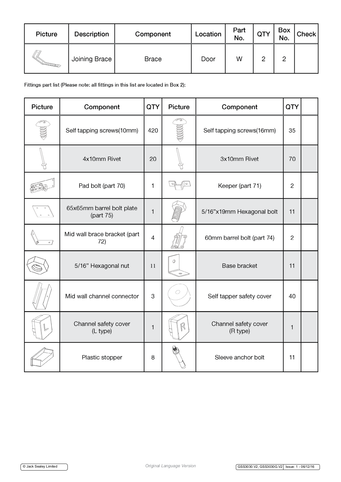
| Joining Brace | Brace | Door | W | 2 | 2 |
Fittings part list (Please note: all fittings in this list are located in Box 2):
| Picture | Component | QTY | Picture | Component | QTY | |
|---|---|---|---|---|---|---|
| Dun | Self tapping screws(10mm) | 420 | Self tapping screws(16mm) | 35 | ||
| 4x10mm Rivet | 20 | 3x10mm Rivet | 70 | |||
| Pad bolt (part 70) | 1 | 0 | Keeper (part 71) | 2 | ||
| 000 |
65x65mm barrel bolt plate
(part 75) |
1 | 5/16"x19mm Hexagonal bolt | |||
|
Mid wall brace bracket (part
72) |
4 | 60mm barrel bolt (part 74) | ||||
| 5/16" Hexagonal nut | 11 | Base bracket | 11 | |||
| Mid wall channel connector | 3 | Self tapper safety cover | 40 | |||
|
Channel safety cover
(L type) |
1 | R |
Channel safety cover
(R type) |
1 | ||
| Plastic stopper | 8 | Sleeve anchor bolt | 11 | |||

© Jack Sealey Limited
Step 2: Assemble the rear wall panels
You will find it easier to assemble your shed using sawhorses with timber studs attached (timber needs to be the same length as the shed (3.0 m)) or alternatively, a trestle table.

Place 4 x part 9F (sheeting) on your work table and join together with self-tapping screws as per the diagram below.

Step 2: Assemble the rear wall panels (continued)
Now fit parts 27I and 27H (top channel) and parts 27C and 27D (bottom channel) to the sheeting by tapping it in (diagram A) or sliding it in (diagram B). Make sure the small lip of the channel is always facing out. This ensures rain water cannot build up inside your shed. Make sure parts 27I and 27H are used as top side channels as per diagram A below.

Tip: If panel and screw holes do not line up, try pulling panel to match up holes.
Step 2: Assemble the rear wall panels (continued)
Now fix parts 35R and 35L (mid wall channels) joined by a mid wall channel connector to the sheeting with self-tapping screws. Please note the groove should face downwards. Fix other channels using self-tapping screws. Apply part 66 (channel connector) to top and bottom channels to enhance the strength. Please note: Screws are applied to both sides of the connectors. All screws marked with a cross should not be fixed at this stage. Make sure the small lip of the channel is always facing out. This ensures rain water cannot build up inside your shed.

© Jack Sealey Limited
Step 3: Assemble side wall panels
Place 4 x part 9F (sheeting) on your worktable and join together with self-tapping screws as per the diagram below. Now fit parts 27K and 27J (top channel) and parts 27A and 27B (bottom channel) to the sheeting by tapping or sliding it in. Make sure the small lip of the channel is always facing out. This ensures rainwater cannot build up inside your shed. Make sure parts 27K and 27J are used as top side channels. Now fix parts 35R and 35L (mid wall channels) joined by a mid wall channel connector to the sheeting with self-tapping screws. Please note: the groove should face downwards. Fix channels with self-tapping screws and apply part 66 (channel connectors) to enhance the structural strength. Note that screws are applied to both sides of the connectors.

Step 3: Assemble side wall panels (continued)
All screws marked with a cross should not be fixed at this stage. Repeat the same steps for the other side wall. Make sure the small lip of the channel is always facing out. This ensures rain water cannot build up inside your shed.

Step 4: Assemble the roof panels
Place parts S30, S31 and 2 x part S32 (sheeting) on your worktable and join together with self-tapping screws as per the diagram below.

Fix parts 27F, 27E, 27A and 27B (channels) using self-tapping screws as per the diagram below. Please ensure parts 27A and 27B are attached to the side of the sheeting which has pre-punched holes as per the diagram below. Make sure the small lip of the channel is always facing out. This ensures rain water cannot build up inside your shed.

Enhance the structural strength by applying part 66 (channel connectors). Note that screws are applied to both sides of the connectors as per Step 3.


Now fix parts 33R and 33L (mid wall channels) to the sheeting using self-tapping screws. Please note the groove should face downwards.

Place part 5K (door sheet) on the worktable. Fit 2 x part M26 and parts 24J and 24H (channels) to the door panel and fix with 3.0 x 10mm rivets as per the diagrams below. Please ensure channel M26 has the smaller lip facing outwards.

Now place 5J (door sheet) on the worktable. Fit parts M27, M28, 24J (channels) and part J21 (jamb) to the door panel and fix with 3.0 x 10mm rivets as per the diagrams below. Please ensure channels M27 and M28 have the smaller lip facing outwards.

Once channels are fitted to both doors, align 2 x part U4 (brace) and part W (joining brace) with holes on the back of the door and position temporarily with some tape or simply hold in place.

Turn door over with bracing still aligned with holes (make sure the ridges of the door are facing up) and fix the bracing with 3.0 x 10mm rivets through the front of the panel. Then turn door over and insert plastic stoppers at the ends of braces as shown below.

FIX WITH 3.0 X 10MM RIVETS

Fix parts 74 (barrel bolt) and 75 (barrel bolt plate) onto part 5J (door) using rivets. Ensure you rivet through the front of the panel with the Padbolt on the inside.

Fit parts 5J and 5K (assembled doors) to the front wall panel as per the diagram below. Use rivet gun and pre-drilled holes. Fix parts 70 (pad bolt) and 71 (keeper) to the door using the pre-drilled holes and 16mm self-tapping screws (or the rivets provided - see diagrams A and B).

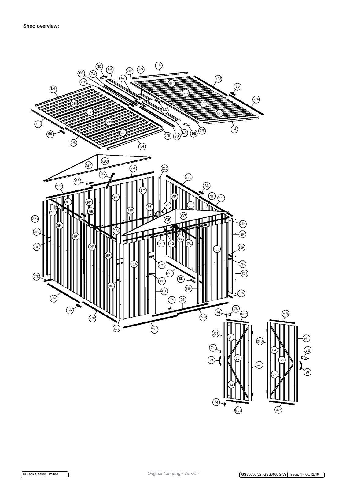
Step 7: Fit the panels together
Now fix the front, side and rear panels and 2 x part G7 and 2 x G8 (gables) together using the holes provided and self-tapping screws. Also attach part Z23 (corner brace) to each corner using the self-tapping screws provided.

Step 7: Fit the panels together (continued)
Join 2 x part 73 (ridge beam) together at the end marked with red arrow using part 67 (ridge beam connector) as per the diagrams below. Put on part E4 (gable caps) and join them using part E3 (gable cap connector). Fix this structure using 16mm self-tapping screws.

Slide the side of the roof panel with channels 27E and 27F into the ridge beam.
© Jack Sealey Limited
Step 7: Fit the panels together (continued)
Repeat the same step for the other assembled roof panel. Drill holes for roof brace using 3mm drill bit. Then fix the roof brace as per the below diagram. Join the sheeting and the gable using part L4 (lip) and then fix the 4 corners using 16mm self-tapping screws. (Do NOT fix central screw marked with a cross at this stage).

Now fit the bolt down kit as per the below diagram. Strengthen your mid wall brace by applying part 72 (mid wall brace bracket) to each corner if necessary. Align part 71 (keeper) with the barrel bolt on the door and fix to the bottom channel using self-tapping screws.

Apply channel safety cover L type to channel 33L and R type to channel 33R for safety. Also apply the self-tapper covers to the screw ends visible in walls on the inside of the shed.

Environmental Protection
Recycle unwanted materials instead of disposing of them as waste. All tools, accessories and packaging should be sorted, taken to a recycling centre and disposed of in a manner which is compatible with the environment. When the product becomes completely unserviceable and requires disposal of it according to local regulations.
NOTE: It is our policy to improve products continually and as such we reserve the right to alter data, specifications and component parts without prior notice.
IMPORTANT: No liability is accepted for incorrect use of this product. WARRANTY: Guarantee is 12 months from purchase date, proof of which will be required for any claim.

Sole UK Distributor, Sealey Group, Kempson Way, Suffolk Business Park, Bury St. Edmunds, Suffolk, IP32 7AR

www.sealey.co.uk sales@sealey.co.uk
© Jack Sealey Limited
Original Language Version
GSS3030.V2, GSS3030G.V2 Issue: 1 - 06/12/16


 Loading...