

Page 1
INSTRUCTIONS FOR
OPEN AND SHORT DC CIRCUIT TESTER
MODEL NO: FF400
Thank you for purchasing a Sealey product. Manufactured to a high standard, this product will, if used according to these
instructions, and properly maintained, give you years of trouble free performance.
IMPORTANT: PLEASE READ THESE INSTRUCTIONS CAREFULLY. NOTE THE SAFE OPERATIONAL REQUIREMENTS, WARNINGS & CAUTIONS. USE
THE PRODUCT CORRECTLY AND WITH CARE FOR THE PURPOSE FOR WHICH IT IS INTENDED. FAILURE TO DO SO MAY CAUSE DAMAGE AND/OR
PERSONAL INJURY AND WILL INVALIDATE THE WARRANTY. KEEP THESE INSTRUCTIONS SAFE FOR FUTURE USE.
1. SAFETY
1.1. GENERAL SAFETY INSTRUCTIONS
9 Familiarise yourself with the application and limitations of the tester as well as the potential hazards. IF IN ANY DOUBT CONSULT A
QUALIFIED ELECTRICIAN.
8 DO NOT apply voltage or current to the meter that exceeds the specified maximum.
9 Only for use with DC voltages.
8 DO NOT connect to a circuit exceeding 42V DC under any circumstances.
8 DO NOT use on AC voltages.
8 DO NOT use on any circuit directly or indirectly connected to AC lines or any other AC power source.
8 DO NOT use with any component or circuits of the ignition system.
9 Modernvehiclescontainextensiveelectronicsystems.YouarerequiredtocheckwiththevehicleManufacturer,foranyspecic
instructions regarding the use of this type of equipment on each vehicle.
No liability will be accepted for damage / injury, where this product is not used in accordance with all instructions.
9 When not in use, store the meter carefully in a safe, dry, childproof location. Storage temperature range -10°C to 50°C.
1.2. PERSONAL PRECAUTIONS
9 When using this tester, please observe all normal safety rules concerning:
9 Protection against the dangers of electronic current.
9 Protection of the meter against misuse.
8 DO NOT use leads if damaged or if the wire is bared in any way.
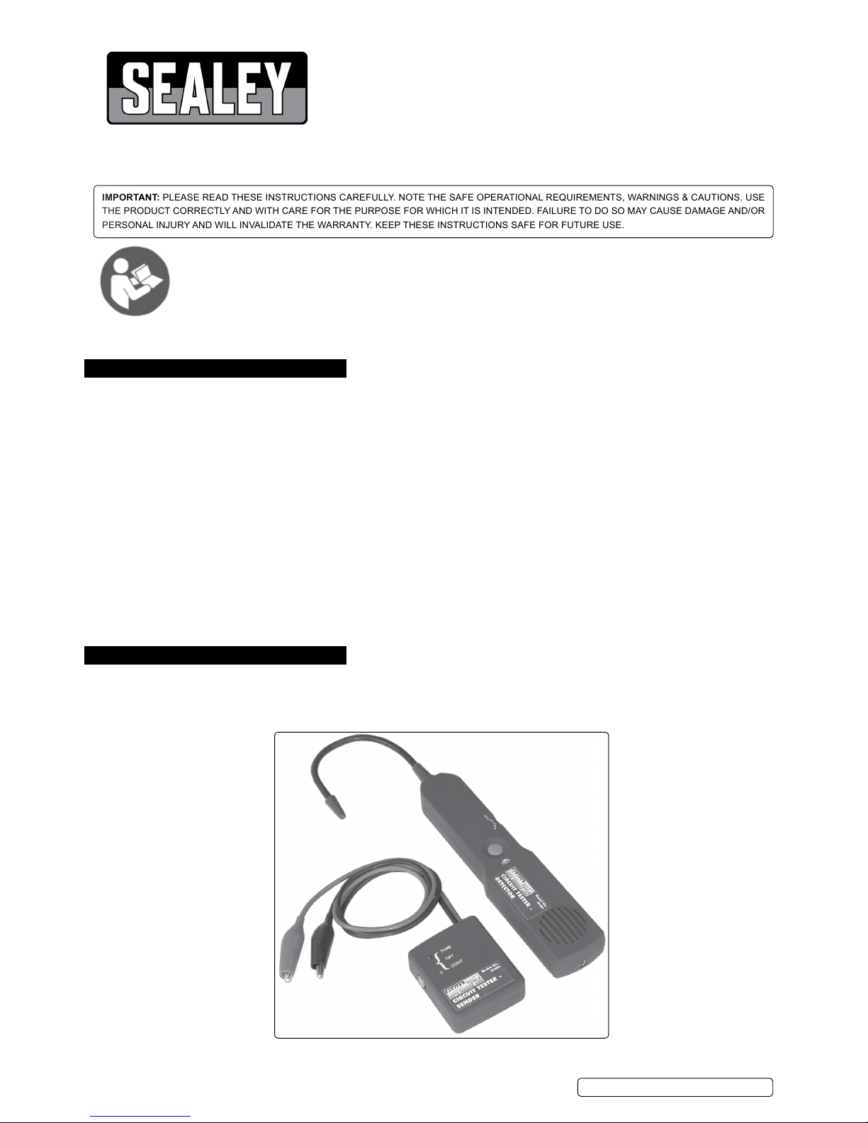
2. INTRODUCTION
Find short and open circuits fast and easily. Simply attach the sender unit to the circuit and follow the wires using the detector. Ideal for
automotive repairs. Suitable for all DC circuits up to 42V. Supplied in carry-case. Powered by two 9V batteries.
FF400 | Issue 2 10/04/17
Original Language Version
© Jack Sealey Limited
Refer to
instructions
Sender
Receiver
Rotary Switch
Selection Switch
Page 2

3. OPERATION
3.1. How to use the probe (fig.1).
3.1.1.
The probe of the receiver is built of coiled steel and may be bent as needed in order to reach wires in congested areas.
Depending on the circuit characteristics and sensitivity settings the probe will pick up the the signal from the wire in a range of
positions. However, for the best possible range the reciever’s probe tip (black cap) should be positioned perpendicular (at 90°) to
the wire being traced and either above or below it.
3.2. Locating short circuit.
3.2.1. Connect the sender in series with the short-circuited wire, making sure one of the test leads is connected to the circuit’s positive supply
(or
connected to the negative for vehicles with positive supply connected to the chassis). A fuse socket (in the place of a blown
fuse), connector etc provides a convenient place.
3.2.2.
Set the switch of the sender to “Tone”, the red LED should light. If the red LED is dim or does not light, please check battery. Set the
rotary switch of the receiver to medium sensitivity position.
3.2.3. Move the probe along the wire, the receiver should give a tone.
3.2.4. Follow the wire or check it at different points, starting from the sender and moving towards the load. Audio signal (beeping sound)
indicates the integrity of the circuit. If the beeping stops it indicates that the probe has passed beyond the short circuit point.
3.2.5.
If it is difficult or impossible to get the receiver to pick up any signal, adjust the rotary switch of receiver and check again.
3.2.6. The short circuit is located in the area where the audio signal stops or changes significantly.
3.3.
Wire Tracing.
3.3.1. Wire tracing hook up and procedures are essentially the same as for locating short circuits. The sender sees the load (light, accessory
etc) as the short circuit or connection to ground. For wire tracing, simply follow the wire with positive (beeping) audio indicators feedback
on the tracer from the source load.
For step by step instructions please refer to 3.2 Locating Short Circuit.
3.4. Locating open circuit.
WARNING ! Observe the limits and safety precautions at all times.
3.4.1. Connect the Sender in series with the open-ended wire, making sure one of the units clips is connected to the circuit’s positive supply or
ground. A fuse socket (with fuse removed), connector etc provides a convenient place as shown in.
3.4.2. Make sure that the clips are firmly attached to their connection points, and set the switch of the Sender to “Tone”. In the case of having
connected the unit in any place other than the fuse socket, check that the circuit fuse is installed and in working condition (not open). If
necessary, replace with a new fuse of the same rating.
3.4.3. Switch Receiver on, and adjust the rotary switch for the correct sensitivity.
3.4.4. Slowly sweep the wire with the Receiver, ensuring that the probe is perpendicular and above or below the wire being traced and as close
as possible to it.
Fuse Socket
or Connector
Light Bulb Socket
or Connector
Fuse Socket
or Connector
Alternate hook-ups for locating open or short circuits and for tracing wires.
g.1
FF400 | Issue 2 10/04/17
Original Language Version
© Jack Sealey Limited
Page 3

3.4.5. Follow the wire or check it at different points, starting from the Sender and moving towards the load (accessory, light etc) observing the
positioning of the probe as indicated above. Continue this procedure while the audio signal (beeping sound) indicates the integrity of
the circuit. If beeping stops, it indicates that the probe has passed beyond the open, break or bad connection in the circuit.
3.4.6. Double check by positioning the probe before and after the suspected place. If the open circuit point has been found, the audio
indicator will show circuit integrity on one side and not the other.
3.4.7. At this point, where the audio signal stops, you have found the open circuit.
3.5. Wire identification.
NOTE ! For connection refer to hook-up options. Wiring can be identified by following the hook up procedures for short and open
circuits, depending on the particular configuration of the circuit.
3.5.1. For identifying wires with load connected, connect sender as described in section Locating Short Circuit to the circuit to be identified,
then proceed to scan all suspected wiring with the receiver’s probe until the beeping is at its maximum. In the case of tightly packed
wires (bundles, conduits etc) it may be necessary to spread these apart to facilitate the identification process of a particular wire.
3.5.2. For identifying wires without load connected. Connect sender as described in section Locating Open Circuit to the circuit to be
identified. Proceed to scan all suspected wiring with the receiver’s probe until the beeping is at its maximum, in the case of tightly
packed wires (bundles, conduits etc) it may be necessary to spread these apart to facilitate the identification process of a particular
wire.
3.6. Special tracing procedures.
3.6.1. In all cases, first set the receiver at the lower sensitivity level and increase it as necessary. Proceed as indicated in the sections of this
user’s manual applicable to your situation. After locating probable fault area, always verify several points in the wires on both sides of
the suspected fault. This procedure helps avoid confusing signal loss with actual trouble point.
3.7. Wire bundles and conduits.
3.7.1. Special care should be taken in the case of tracing a wire inside a bundle or conduit when there is a split. In this case it may be
possible to follow the wrong branch for a short distance and still receive a positive audio indication.
3.7.2. The probe may be picking up the signal from the other nearby branch (the one with the wire actually being traced). To avoid following
the wrong path, the branches should be swept, while maintaining the probe outside the apex area between the split as shown in fig.2.
Careful attention should be paid to the beeping of the tracer unit indicator, as it provides the necessary feedback to evaluate the
proximity of the wire being traced.
3.8. To increase the pickup range when tracing wires.
3.8.1. When tracing or identifying wires connected to a lightly loaded circuit (low currents), pickup range is reduced significantly. A possible
solution is, after connecting the sender in series with the circuit to trace, to replace the load (light bulb, module etc) with a direct
connection to ground. This allows the sender to inject a more powerful signal that is easier to detect.
3.8.2. For cases in which it is suspected the layout of the wires is the cause of a difficult pickup or weak signal, a dramatic increase of the
range can be accomplished by spreading the circuit. This is achieved by means of connecting a jumper wire between the sender’s live
wire and a ground point (fig.3) somewhere else on the vehicle. This last method should be used only as a last resort and with the
receiver set to low sensitivity, as it may make pinpointing of the precise location more difficult due to the much increased range.
3.8.3. Always verify that the sender is connected in series with the circuit being tested, as this confirms a proper connection and will limit the
amount of current flowing in the circuit.
3.9. Circuits with multiple loads or branches. (fig.4)
3.9.1. When tracing circuits connected to, or powering multiple loads and/or branches, and when these circuits are active or live, the bulk of
the current injected into the circuit by the sender will be directed to the short circuited branch of the circuit. However smaller amounts
of current (or stray current) will flow elsewhere making the tracing procedure confusing or even misleading.
3.9.2. The simplest and most effective way to deal with these cases is to disconnect or remove all loads from the circuit being traced (i.e
remove the light bulbs in fig.4).
g.2
g.3
FF400 | Issue 2 10/04/17
Original Language Version
© Jack Sealey Limited
Page 4

NOTE: It is our policy to continually improve products and as such we reserve the right to alter data, specications and component parts without prior notice.
IMPORTANT: No liability is accepted for incorrect use of this product.
WARRANTY: Guarantee is 12 months from purchase date, proof of which will be required for any claim.
Sole UK Distributor, Sealey Group.
Kempson Way, Suffolk Business Park,
Bury St. Edmunds, Suffolk.
IP32 7AR
www.sealey.co.uk
sales@sealey.co.uk
01284 757500
01284 703534
Environmental Protection
Recycle unwanted materials instead of disposing of them as waste. All tools, accessories and packaging should be
sorted, taken to a recycling centre and disposed of in a manner which is compatible with the environment.
When the product becomes completely unserviceable and requires disposal, drain off any fluids (if applicable)
into approved containers and dispose of the product and the fluids according to local regulations.
WEEE Regulations
Dispose of this product at the end of its working life in compliance with the EU Directive on
Waste Electrical and Electronic Equipment (WEEE). When the product is no longer required, it must be disposed
of in an environmentally protective way. Contact your local solid waste authority for recycling information.
Battery Removal
See section 4.4
Under the Waste Batteries and Accumulators Regulations 2009, Jack Sealey Ltd are required to inform potential
purchasersofproductscontainingbatteries(asdenedwithintheseregulations),thattheyareregisteredwihValpak’s
registered compliance scheme. Jack Sealey Ltd’s Batteries Producer Registration Number (BPRN) is BPRN00705.
4. MAINTENANCE
WARNING! DO NOT
attempt to repair or service your FF400 unless you are qualified to do so. To avoid damage to the FF400 do not get water
inside the case.
4.1. Periodically wipe the case with a damp cloth and mild detergent. Do not use solvents.
4.2. Turn the sender and receiver off when not in use and remove the batteries if stored for a long period of time.
4.3. Do not store in a place of high humidity or high temperature.
4.4. To replace the batteries on either the sender or the receiver, simply undo the Philip’s screw on the rear of the unit battery cover and
replace the battery with a 9V PP3.
g.4
FF400 | Issue 2 10/04/17
Original Language Version
© Jack Sealey Limited
 Loading...