

Page 1
INSTRUCTIONS FOR
MIGHTYMIG
WELDERS
EEMM113300XXTT..VV33
PPMM114400XXTT..VV22
PPMM115500XXTT..VV22
Models:
EM130XT.V3, PM140XT.V2, PM150XT.V2 - 3 - 130206
PM150XT.V2
Page 2
INSTRUCTIONS FOR: MIGHTYMIG WELDERS
MODEL NOS: EM130XT.V3
PM140XT.V2
PM150XT.V2
Thank you for purchasing a Sealey Welder. Manufactured to a high standard this product will, if used
according to these instructions and properly maintained, give you years of trouble free performance.
IMPORTANT: BEFORE USING THIS PRODUCT, PLEASE READ THE INSTRUCTIONS CAREFULLY. MAKE CAREFUL NOTE OF SAFETY INSTRUCTIONS,
WARNINGS AND CAUTIONS. THIS PRODUCT SHOULD ONLY BE USED FOR ITS INTENDED PURPOSE. FAILURE TO DO SO MAY CAUSE DAMAGE
AND/OR PERSONAL INJURY AND WILL INVALIDATE THE WARRANTY. RETAIN THESE INSTRUCTIONS FOR FUTURE USE.
1. SAFETY INSTRUCTIONS
1.1. ELECTRICAL SAFETY
!
WARNING! It is the user’s responsibility to read, understand and comply with the following:
You must check all electrical equipment and appliances to ensure they are safe before using. You must inspect power supply leads, plugs and all electrical connections for wear and damage. You must ensure the risk of electric shock is minimised by the installation of appropriate safety devices. An RCCB (Residual Current
Circuit Breaker) should be incorporated in the main distribution board. We also recommend that an RCD (Residual Current Device) is used with all electrical products. It is particularly important to use an RCD together with portable products that are plugged into an electrical supply not protected by an RCCB. If in doubt consult a qualified electrician. You may obtain a Residual Current Device by contacting your Sealey dealer. You must also read and understand the following instruc-
tions concerning electrical safety.
1.1.1. The Electricity At Work Act 1989 requires all portable electrical appliances, if used on business premises, to be tested by a qualified electrician, using a
Portable Appliance Tester (PAT), at least once a year.
1.1.2. The Health & Safety at Work Act 1974 makes owners of electrical appliances responsible for the safe condition of the appliance, and the safety of the
appliance operator. If in any doubt about electrical safety, contact a qualified electrician.
1.1.3. Ensure the insulation on all cables and the product itself is safe before connecting to the mains power supply.
See 1.1.1. & 1.1.2. above and use a Portable Appliance Tester (PAT).
1.1.4. Ensure that cables are always protected against short circuit and overload.
1.1.5. Regularly inspect power supply leads, plugs and all electrical connections for wear and damage and especially
power connections, to ensure that none is loose.
1.1.6. Important: Ensure the voltage marked on the product is the same as the electrical power supply to be
used and check that plugs are fitted with the correct capacity fuse. A 13 amp plug may require a fuse
smaller than 13 amps for certain products, see fuse rating at right.
1.1.7. DO NOT pull or carry the powered appliance by its power supply lead.
1.1.8. DO NOT pull power plugs from sockets by the power cable.
1.1.9. DO NOT use worn or damage leads, plugs or connections. Immediately replace or have repaired by
a qualified electrician. A U.K. 3 pin plug with ASTA/BS approval is fitted. In case of damage, cut off
and fit a new plug according to the following instructions (discard old plug safely).
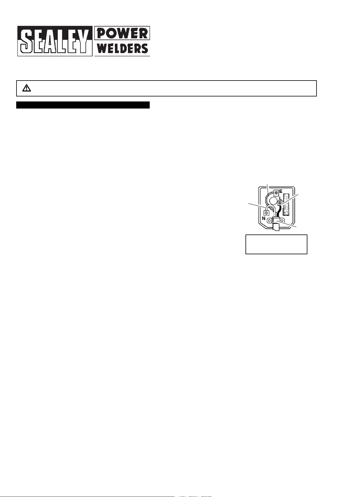
(UK only - see diagram at right). Ensure the unit is correctly earthed via a three-pin plug.
a) Connect the GREEN/YELLOW earth wire to the earth terminal ‘E’.
b) Connect the BROWN live wire to live terminal ‘L’.
c) Connect the BLUE neutral wire to the neutral terminal ‘N’.
d) After wiring, check that there are no bare wires, that all wires have been correctly connected,
that the cable external insulation extends beyond the cable restraint and that the restraint is tight.
1.1.10. Some products require more than a 13 amp electrical supply. In such a case, NO plug will be fitted. You must contact a qualified electrician to ensure
that a 30 amp fused supply is available. We recommend you discuss the installation of a industrial round pin plug and socket with your electrician.
1.1.11. Cable extension reels. When a cable extension reel is used it should be fully unwound before connection. A cable reel with an RCD fitted is recommended
since any product which is plugged into the cable reel will be protected. The section of the cable on the cable reel is important and should be at least
1.5mm
2
, but to be absolutely sure that the capacity of the cable is suitable for this product and for others that may be used in the other output sockets, we
recommend the use of 2.5mm
2
section cable.
!
WARNING! Be very cautious if using a generator to power the welder. The generator must be self-regulating and stable with
regard to voltage, wave form and frequency. The output must be greater than the power consumption of the welder. If any
of these requirements is not met the electronics within the welder may be affected.
NOTE: The use of an unregulated generator may be dangerous and will invalidate the warranty on the welder.
!
WARNING! The welder may produce voltage surges in the mains supply which can damage other sensitive equipment
(e.g. computers). To prevent this happening, it is recommended that the welder is connected to a power supply that does
not feed any sensitive equipment.
Blue
Neutral
Wire
Yellow & Green
Earth Wire
Cable
Restraint
FUSE RATING
13 AMP
Brown
Live
Wire
1.2. GENERAL SAFETY
""
DANGER! Unplug the welder from the mains power supply before performing maintenance or service.
# Keep the welder and cables in good working order and condition. (Take immediate action to repair or replace damaged parts).
# Use genuine parts and accessories only. (Unapproved parts may be dangerous and will invalidate the warranty).
# Use an air hose to regularly blow out any dirt from the liner and keep the welder clean for best and safest performance.
# Check and spray the gas cup and contact tip regularly with anti-spatter spray, available from your Sealey dealer.
# Locate welder in a suitable work area. Ensure that the area has adequate ventilation as welding fumes are harmful.
# Keep work area clean, tidy and free from unrelated materials. Also ensure the working area has adequate lighting and that a fire extinguisher is at hand.
!!
WARNING! Use welding head shield to protect eyes and avoid exposing skin to ultraviolet rays given off by electric arc. Wear safety welding gauntlets.
# Remove ill fitting clothing, remove ties, watches, rings and other loose jewellery and contain long hair.
# Ensure the workpiece is correctly secured before welding.
# Avoid unintentional contact with the workpiece. Accidental or uncontrolled use of the torch may be dangerous and will wear the nozzle.
# Keep unauthorised persons away from the work area. Any persons working within the area must wear a protective head shield and gloves.
# Operators must receive adequate training before using the welder.
# Stand correctly keeping a good footing and balance, ensure the floor is not slippery and wear non-slip shoes.
% DO NOT operate the welder if it or the cables are damaged and DO NOT attempt to fit any unapproved torches or other components to the welder.
% DO NOT get welder wet or use in damp or wet locations or areas where there is condensation.
""
DANGER! DO NOT weld near inflammable solids, liquids or gases and DO NOT weld containers or pipes which have held inflammable materials.
Avoid welding materials which have been cleaned with chlorinated solvents or welding near such solvents.
% DO NOT stand welder on a metal workbench, car bodywork or similar.
% DO NOT touch any live metal parts of the torch or electrode while the machine is switched on.
% DO NOT pull the welder by the cable, or the torch. Protect cables from sharp or abrasive items, DO NOT bend, strain or stand on cables or leads. Protect from
heat. Long lengths of slack must be gathered and neatly coiled. DO NOT place cables where they endanger others.
% DO NOT touch the torch or workpiece immediately after welding as they will be very hot. Allow to cool.
% DO NOT operate welder while under the influence of drugs, alcohol or intoxicating medication, or if tired.
# When not in use store the welder in a safe, dry, childproof area.
EM130XT.V3, PM140XT.V2, PM150XT.V2 - 3 - 130206
Page 3

2. INTRODUCTION & SPECIFICATIONS
IMPORTANT: These instructions contain the information you require to prepare your machine for welding, together with maintenance and a trouble shooting
section. The instructions are not intended to teach you how to weld. If you have no experience, we recommend that you seek training from an expert source. MIG
welding is relatively easy, but does require a steady hand and supervised practice on scrap metal, as it is only with continued practice that you will achieve the
desired results.
Your Mightymig welder features a heavy duty high output transformer and forced air cooling to ensure the highest level of performance. Contoured grip torches run
cooler than any other and are comfortable in the hand, thus ensuring a steadier weld bead. Supplied with a hand held mask, disposable cylinder of CO
2
gas,
mini gas regulator, spool of mild steel wire and torch. Can also be connected to large, industrial CO
2
gas bottles using the optional adaptor kits AK9 or AK9/3. To weld
aluminium, order a roll of 0.8mm aluminium wire, a packet of 0.8mm contact tips, and a bottle of Argon gas. See our catalogue for details of welding accessories.
3. ASSEMBLY & PREPARATION
3.3. Fitting the reel spindle and wire reel. The welder is supplied with a mini spool of mild steel wire, but will
accept spools of up to 5kg without modification.
3.3.1. Align the reel spindle (fig.4. A) with the holes in the internal side panel and secure with two self tapping
screws (B). Place the wire reel (C) onto the spindle ensuring that the spool rotates anticlockwise with the
wire drawing off the bottom of the reel for the PM140XT and PM150XT (see fig.5) and clockwise, with the
wire drawing off the reel from the top for the EM130XT (see fig.7). Place the plastic reel ring nut (D) over
the end of the spindle followed by the reel spring (E). Push the ‘handwheel’ stub (F) into the end of the
spindle against the spring pressure and turn and release it to lock it in position.
3.3.2. Unscrew the wire feed pressure knob and lift the wire feed lever up to the right (fig. 6).
3.3.3. Straighten about 40-50mm of spool wire (do not allow wire to uncoil) and check that the wire end is
smooth and free from burrs. Gently push wire through the plastic guide and through the 6 or 8mm roller
groove and into the wire liner as indicated in fig.6
3.3.4. Hinge down the tension arm and secure with the wire feed knob. (See section 3.4 re wire tension.)
Model No. . . . . . . . . . . . . . . . . . . . . . . . . . . . . . . . . .EM130XT . . . . . . . . . . . . . . . . . . . . . . . . . . . . .PM140XT . . . . . . . . . . . . . . . . . . . . . . . . . . . . .PM150XT
Welding Current . . . . . . . . . . . . . . . . . . . . . . . . . . . .35 - 130A . . . . . . . . . . . . . . . . . . . . . . . . . . . . .35 - 140A . . . . . . . . . . . . . . . . . . . . . . . . . . . . .30 - 150A
Wire Capacity-steel . . . . . . . . . . . . . . . . . . . . . . . . .0.7 - 5.0kg . . . . . . . . . . . . . . . . . . . . . . . . . . . . .0.7 - 5.0kg . . . . . . . . . . . . . . . . . . . . . . . . . . . .0.7 - 5.0kg
Wire Capacity-aluminium . . . . . . . . . . . . . . . . . . . .0.5 - 2.0kg . . . . . . . . . . . . . . . . . . . . . . . . . . . . .0.5 - 2.0kg . . . . . . . . . . . . . . . . . . . . . . . . . . . .0.5 - 2.0kg
Duty Cycle . . . . . . . . . . . . . . . . . . . .100% @ 35A, 50% @55A . . . . . . . . . . . . . . . .100% @ 35A, 60% @ 50A . . . . . . . . . . . . . . . .100% @ 45A, 60% @ 55A
. . . . . . . . . . . . . . . . . . . . . . . . . . . . . . . . . . . . . . .20% @ 80A . . . . . . . . . . . . . . . .20% @ 90A, 15% @ 105A . . . . . . . . . . . . . . . . . . . . . . . . . .15% @ 115A
Penetration-steel . . . . . . . . . . . . . . . . . . . . . . . . . . . . . . .2mm . . . . . . . . . . . . . . . . . . . . . . . . . . .2.5 - 3.5mm . . . . . . . . . . . . . . . . . . . . . . . . . . .3.5 - 4.5mm
Penetration-aluminium . . . . . . . . . . . . . . . . . . . . . . . . . .3mm . . . . . . . . . . . . . . . . . . . . . . . . . . . . . . . . .4mm . . . . . . . . . . . . . . . . . . . . . . . . . . . . . . . . .5mm
Cooling System . . . . . . . . . . . . . . . . . . . . . . . . . . . .Forced Air . . . . . . . . . . . . . . . . . . . . . . . . . . . . .Forced Air . . . . . . . . . . . . . . . . . . . . . . . . . . . . .Forced Air
Gas Type . . . . . . . . . . . . . . . . . . . . . . .CO
2
/argon mix & argon . . . . . . . . . . . . . . . . . . .CO2/argon mix & argon . . . . . . . . . . . . . . . . . . .CO2/argon mix & argon
Torch . . . . . . . . . . . . . . . . . . . . . . . . . . . . . . . . . . . . . .Non-live . . . . . . . . . . . . . . . . . . . . . . . . . . . . . .Non-live . . . . . . . . . . . . . . . . . . . . . . . . . . . . . .Non-live
Power Input . . . . . . . . . . . . . . . . . . . . . . . . . . . . . . .230V 1ph . . . . . . . . . . . . . . . . . . . . . . . . . . . . .230V 1ph . . . . . . . . . . . . . . . . . . . . . . . . . . . . .230V 1ph
Power Efficiency . . . . . . . . . . . . . . . . . . . . . . . . . . . . .2.8kVA . . . . . . . . . . . . . . . . . . . . . . . . . . . . . . .4.0kVA . . . . . . . . . . . . . . . . . . . . . . . . . . . . . . .4.3kVA
1.3. GAS SAFETY
# Store gas cylinders in a vertical position only and ensure the storage area is correctly secured.
% DO NOT store gas cylinders in areas where the temperature may exceed 50°C. DO NOT use direct heat on a cylinder. Always keep gas cylinders cool.
% DO NOT attempt to repair or modify any part of a gas cylinder or valve and DO NOT puncture or damage a cylinder.
% DO NOT obscure or remove any official labels on a cylinder. Always check the gas identity before use. Avoid getting gas cylinders oily or greasy.
% DO NOT lift a cylinder by the cap, guard or valve. Always keep caps and guards in place and close valve when not in use.
3.1. Wheel assembly for models PM140XT & PM150XT
3.1.1. Take the wheel axle and fit a wheel to one end.
Secure with a circlip. Pass the axle through the
lower part of the rear moulded frame then fit the
other wheel and circlip. Press fit the caps provided
into the recesses in each wheel.
3.2. Connecting the gas cylinder (See Section 4.4
regarding gas types)
3.2.1. For the EM130XT attach the red gas cylinder belt to
the back of the welder by passing it through the
metal loops in the back panel just below the handle.
Place the lower end of the cylinder into the metal
hoop and fasten the belt around the cylinder as
shown in fig.2. For the PM140XT & PM150XT pass
the belt through either side of the rear moulded frame
as shown in fig.3. Hold the gas cylinder in place in
the recesses provided in the rear moulding and
fasten the belt around the cylinder.
3.2.2. Ensure that the regulator (fig. 1) is closed (knob turned fully clockwise) and then screw it onto the cylinder (finger tight only). Once the regulator has
opened the cylinder valve, indicated by the sound of gas escaping, screw it one full turn further, which is sufficient to seal the cylinder.
! WARNING! Excessive tightening of the regulator will over-compress the sealing washer and allow the gas to leak.
3.2.3. Push the gas tube into the quick connector on the regulator ( to remove tube, press collet in and pull the tube. See fig.1.)
Leave the regulator closed until the welder is fully set up and you are ready to weld.
3.2.4. When you are ready to commence welding switch the machine on and turn the regulator knob halfway for approx. 2l/min, and all the way for a max. flow of
approx. 4l/min.
3.2.5. Always remove the flow regulator after use if the machine is to be stored for any length of time.
fig. 5
fig. 6
fig.1
fig.2
fig. 3
fig. 4
fig.7
EM130XT.V3, PM140XT.V2, PM150XT.V2 - 3 - 130206
Page 4

5. RATINGS PLATE
On the front of the welder is the ratings plate, giving the following data:
1 - The standard relating to the safety and construction of arc
welding and associated equipment.
2 - Inverter-transformer-rectifier.
3 - Welding with a continuous flow of welding wire.
4 - Single-phase AC supply.
5 - Rating of internal protection provided by casing.
6-Output
U
0: Maximum open-circuit voltage.
I
2, U2: Current and corresponding voltage.
X: Welding ratio based on a 10 minute cycle. 30% indicates 3 minutes welding and 7 minutes rest, 100% indicates continuous
welding. A/V-A/V: Welding current adjustment range and corresponding voltages.
7 - Mains Supply U
1
: Rated supply voltage and frequency. I
max
: Maximum current. I
1eff
: Maximum effective current.
8 - : Delayed fuse for supply protection and ‘symbols referring to safety’.
9 - Serial Number. Specifically identifies each welder.
10 - S: Indicates welding may be carried out in environments with a heightened risk of electric shock e.g. very close to large metallic objects.
4.1. Mig/Mag welding
Welding wire is automatically fed through an insulated liner to the tip of the torch. The torch consists
of a switch, liner, gas hose, and control cable. The switch activates the wire feed roller and the gas
flow. Releasing the switch stops wire feed and gas flow. The weld current is transferred to the
electrode (the wire) from the contact tip at the torch end. Four settings control the current to the
electrode. Settings are Min/1 = low, then Min/2, Max/1 and Max/2 = high. Wire speed must be
adjusted according to current output. The higher the current the faster the wire speed. A gas cup fits over
the contact tip to direct gas flow towards the weld, ensuring that the arc welding process is shielded
from oxidisation. The shielding gas also assists heating of the weld. The torch is connected to the
positive side of a DC rectifier, and the negative clamp is attached to the workpiece.
4.2. Spot welding (The PM150XT torch can be fitted with a spot welding gas cup.)
Remove the existing gas cup and fit a spot welding gas cup. Select the highest current and wire
speed settings. Drill a small hole in the top workpiece. Push the spot gas cup onto the material to be
welded. The castelations on the cup keep it the correct distance from the weld pool and allow you to
push the two workpieces together. Press the torch trigger and hold for 2 to 3 seconds. The wire will feed through during the allotted time
and create the weld.
4.3. Preparation for welding
IMPORTANT! BEFORE YOU COMMENCE, MAKE SURE THE MACHINE IS SWITCHED OFFAT THE MAINS. IF WELDING A CAR,
DISCONNECT THE BATTERY OR FIT AN ELECTRONIC CIRCUIT PROTECTOR. ENSURE THAT YOU READ, UNDERSTAND AND
APPLY THE SAFETY INSTRUCTIONS IN SECTION 1.
4.3.1. To ensure a complete circuit, the negative lead must be securely attached to the workpiece, close to the weld area. Best connection is
obtained by grinding the point of contact on the workpiece before connecting the clamp.
4.3.2. The weld area must be free of paint, rust, grease, etc.
4.4. Gas types and their use
Welding mild steel with CO
2 gas (supplied with unit) is appropriate for most welding tasks where spatter and high build up of weld do not pose a problem.
To achieve a spatter free and flat weld however, requires an Argon/CO
2 mixture.
4.4.1. To weld aluminium use: #Argon Gas #0.8mm Contact Tip #0.8mm Aluminium Wire (MIG/2/KAL08).
4.4.2. The following table is an estimated duration of cylinders based on a flow rate of 2 litres per minute. Actual duration will be dependant upon various
job conditions including the operator’s welding technique. All times are therefore approximate.
a) Refillable cylinder: CO2/200 300g = 1 hour (refill service via Sealey dealers).
b) Disposable cylinders: CO
2
/100 390g = 1-1/4hours. CO2/101 600g = 2 hours. Argon ARG/100 300g = 1 hour. Argon/CO2MIX/100 300g = 1 hour.
Note: When comparing prices, always check fill weights.
4. WELDING PRINCIPLES
3.3.5. Feeding the wire through to the torch.
MODELS E130XT
& PM140XT. Unscrew and remove the gas cup (fig.8a) and the copper contact tip (fig.8b).
Then follow points 3.3.7. to 3.3.10.
3.3.6. MODEL PM150XT ONLY. Remove gas cup and contact tip from end of torch as follows:
a) Take torch in left hand with the torch tip facing to the right and grasp gas cup with your right hand.
b) Turn gas cup clockwise only and pull cup out to the right (fig. 8).
! WARNING! Do not turn gas cup anti-clockwise, as this will damage the internal spring.
c) Unscrew the copper contact tip (right-hand thread) to remove.
3.3.7. Check welder is switched off “O”, (I/O switch, figs.10 & 11) and that the earth clamp is away from the torch
tip. Connect the welder to the mains power supply and set the current switches (Max/Min and 1/2 switches,
figs.10 & 11) to ‘Min 1’.
3.3.8. Set the wire speed knob to position 5 or 6 (figs.10 & 11) (the higher the number the faster the speed).
3.3.9. Switch the welder on “I”, keep the torch cable as straight as possible and press the torch switch. The wire will
feed through to the torch.
3.3.10. When wire has fed through, switch welder off and unplug from mains.
3.3.11 Models PM EM130XT & PM140XT. Thread contact tip over wire and screw into place. Screw gas cup back onto torch.
3.3.12. Model PM150XT only. a) Thread contact tip over wire and screw into place.
b) Grasp gas cup in right hand, push onto torch head and turn clockwise only.
! WARNING! Do not turn gas cup anticlockwise, as this will damage the internal spring.
3.3.13. All models. Cut wire so that it is protruding approximately 1/4” from the tip.
3.4. Setting wire tension
IMPORTANT: Too little or too much tension will cause erratic wire feed and result in poor welding.
3.4.1. For 0.6mm mild steel wire the wire feed tension screw must be tightened fully and undone approximately two
complete turns (fig. 9).
3.4.2. Tension between rollers is checked by slowing down the wire between your fingers. If top feed roller skids
the tension is correct. Use as low a tension as possible, too high a tension will deform the wire and result in a
blown fuse.
fig. 8
PM150XT
only
fig. 11
fig. 10
fig. 9
EM130XT.V3, PM140XT.V2, PM150XT.V2 - 3 - 130206
Page 5

6.1. Wire feed unit Check the wire feed unit at regular intervals. The feed roller wire guide plays an
important part in obtaining consistent results. Poor wire feed affects welding. Clean the rollers
weekly, especially the feed roller groove, removing all dust deposits.
6.2. Torch Protect the torch cable assembly from mechanical wear. Clean the liner from the machine
forwards by using compressed air.If the liner is blocked it must be replaced.
6.3. Turning feed roller IMPORTANT: Turn the feed roller to suit the wire size.There are two
grooves on the feed roller, 0.6mm and 0.8mm. Always have the groove that is being used on the
outside of the roller (nearest to you). To turn the feed roller, undo the two screws and remove
the plastic cover (fig.12). Clean and turn the feed roller and then replace the plastic cover.
6. 4. Contact tip (to remove tip follow steps in 3.3.) The contact tip is a consumable item and
must be replaced when the bore becomes enlarged or oval. The contact tip MUST be kept free
from spatter to ensure an unimpeded flow of gas.
6.5. Gas cup (to remove cup follow steps in 3.3.) The gas cup must also be kept clean and free
from spatter. Build-up of spatter inside the gas cup can cause a short circuit at the contact tip which
will result in either the fuse blowing on the printed circuit card, or expensive machine repairs. To keep
the contact tip free from spatter, we recommend the use of Sealey anti-spatter spray (MIG/722307)
available from your Sealey dealer.
6.6. Replacing wire liner Wind the wire back onto the spool and secure it. Remove three screws
securing the torch cable clamp to the wire feed unit (fig.13). Take off the clamp. Undo the torch case
and disconnect wire liner from torch head. Pull out the liner (fig. 13) and insert the new one. Reverse
the process to re-assemble and trim the liner as close to the feed roller as possible.
6.7. Replacing gears An inexperienced welder can allow spatter to build up in the tip and shroud.
In severe cases this can block the wire feed causing gear damage in the wire drive. To check if the
gears are worn depress the button on the torch with the set switched on. If the gears are worn,
a grating sound will be heard coming from the wire feed motor and you may also observe the
feed roller vibrating instead of rotating smoothly. In this case, open the gearbox, remove the worn
or damaged gears and replace with new ones.
6.8. Wire drive fuse (PM140XT & PM150XT)
The fuse (250V 1.5/1.6A) is located on the small printed circuit board inside the welder and the
following may cause it to blow:
# Spatter collecting in the gas cup, causing contact tip to short circuit. # Wire tension too great.
# Sudden surge of current.
6. MAINTENANCE
fig. 12
fig. 13
Weld current interrupted
No weld current, fuse blowing in 13amp plug
No weld current
Feed motor not working
Wire does not feed, feed roller rotates
Wire feeds unevenly
Unstable arc
Porous weld
Wire sticking in gas cup (nozzle)
Irregular weld head
Weld bead too narrow and raised
Weld bead too wide
Poor penetration
Excessive penetration
Wire drive fuse blowing
Overheating protection activated due to overload
Rectifier blown
Bad connection between clamp and workpiece
Break in earth lead
Break in torch lead
Fuse blown
Gear damaged or worn
Motor defective
Pressure roller improperly adjusted
Dirt, copper, dust, etc. have collected in torch liner
Gas cup (nozzle) or tip defective
Deformed wire
Dirt, etc, in liner
Gas cup (nozzle) or tip defective
Gas cup (nozzle) spattered
Feed roller groove clogged
Feed roller groove deformed
Pressure roller tension incorrect
Incorrect settings
Impurities in weld area
Worn or defective gas cup (nozzle)
No gas
Gas cup clogged
Draft blowing away shielding gas
Rusty/dirty joints
Torch too far from, or at wrong angle to, workpiece
Gas leak
Worn or defective gas cup (nozzle)
Wire deformed
Wire speed too slow
Torch incorrectly held
Wire weaving in weld pool
Weld current too low
Weld speed too fast
Weld current too high
Weld speed too slow
Arc too long
Weld current too low
Arc too long
Weld current too high
Weld speed too slow
Incorrect distance of torch to workpiece
Wire tension too great
Gas cup contact tip clogged
PROBLEM POSSIBLE CAUSE REMEDY
7. TROUBLESHOOTING
Protection automatically resets when transformer has cooled (approx. 15 min).
Replace rectifier.
Clean or grind contact surface and weld area.
Repair or replace earth lead.
Repair or replace.
Replace fuse 1.5 amp (Section 6).
Replace gears (Section 6).
Replace motor (Contact service agent).
Adjust tension.
Clean the liner from the machine forward. Use compressed air. If too much dirt,
replace the liner (Section 6).
Replace gas cup (nozzle) and/or tip (Section 6). Check roller tension (Section 3).
Clean the liner from the machine forward using compressed air.
Replace gas cup (nozzle) and/or tip (Section 6).
Clean or replace gas cup (nozzle) (Section 6).
Clean feed roller (Section 6).
Replace feed roller (Section 6).
Adjust tension (Section 3).
Check settings (Section 4).
Clean and/or grind workpiece (Section 4).
Replace gas cup (nozzle) (Section 6).
Open gas cylinder, regulate gas flow.
Clean or replace cup (Section 6).
Screen off welding site or increase gas flow.
Clean or grind the workpiece (Section 4).
Gas cup to workpiece should be 8-10mm. Torch angle approx 75
O
.
Check hoses, connections and torch assembly (Section 6).
Replace gas cup (nozzle) (Section 6).
Check roller tension (Section 3).
Increase wire speed.
Use correct torch angle.
Check roller tension and adjust (Section 3).
Increase power and wire speed (Section 4).
Move torch slower and weave a little more.
Decrease current and wire speed (Section 4).
Move torch faster and weave less.
Bring torch closer to workpiece.
Increase current and wire speed (Section 4).
Bring torch closer to workpiece.
Decrease current and wire speed (Section 4).
Move torch faster.
Torch distance should be 8-10mm.
Reduce tension (Section 3).
Clean gas cup and contact tip (Section 6).
EM130XT.V3, PM140XT.V2, PM150XT.V2 - 3 - 130206
Page 6

TORCH for EM130XT.V3 & PM140XT.V2
Item Part No. Description
1 120/ 722667 Contact Tip, Ø0.8mm
2 120/722054 Cylindrical Nozzle
3 120/722810 Swan Neck
4 120/990464 Torch Connection Asm.
5 120/452097 Contact Spring
Item Part No. Description
6 120/322295 Push Button
7 120/990600 Sleeve with cable
8 120/990465 Complete Handle
9 120/742412 Wire Liner
- 120/742900 Torch, Complete
NOTE: It is our policy to continually improve products and as such we reserve the right to alter data, specifications and component parts without prior notice.
IMPORTANT: No liability is accepted for incorrect use of product.
WARRANTY: Guarantee is 12 months from purchase date, proof of which will be required for any claim.
INFORMATION: For a copy of our latest catalogue and promotions call us on 01284 757525 and leave your full name and address, including postcode.
01284 757500
01284 703534
sales@sealey.co.uk
Sole UK Distributor
Sealey Group,
Bury St. Edmunds, Suffolk.
www.sealey.co.uk
Web
email
EM130XT.V3, PM140XT.V2, PM150XT.V2 - 3 - 130206
 Loading...