

Page 1
HYDRAULIC DRUM LOADER
MODEL NO: DH03.V2
Thank you for purchasing a Sealey product. Manufactured to a high standard, this product will, if used according to these instructions,
and properly maintained, give you years of trouble free performance.
IMPORTANT: PLEASE READ THESE INSTRUCTIONS CAREFULLY. NOTE THE SAFE OPERATIONAL REQUIREMENTS, WARNINGS & CAUTIONS. USE THE
PRODUCT CORRECTLY AND WITH CARE FOR THE PURPOSE FOR WHICH IT IS INTENDED. FAILURE TO DO SO MAY CAUSE DAMAGE AND/OR PERSONAL
INJURY AND WILL INVALIDATE THE WARRANTY. KEEP THESE INSTRUCTIONS SAFE FOR FUTURE USE.
Refer to the instruction manual
Wear Safety footwear
Warning; Crushing of hands
Wear protective gloves
1. SAFETY
1.1 GENERAL SAFETY
▲ DANGER! When assembling, it is recommended that it is by two people.
Familiarise yourself with this products application and limitations, as well as the specific potential hazards peculiar to the drum loader.
Maintain the drum loader in good condition including lubrication (use an authorised service agent for mechanical maintenance).
Replace or repair damaged parts. Use recommended parts only. Non authorised parts may be dangerous and will invalidate the
warranty.
Keep the drum loader clean for best and safest performance.
Operate the drum loader in a suitable working area for its function, level even concrete flooring (avoid tarmacadum), keep the area
clean and tidy and ensure there is adequate lighting.
Ensure the load is correctly secured before transporting.
Keep hands and body clear of the rim grab mechanism when engaging the drum.
Maintain correct balance and footing. Ensure the floor is not slippery and wear non-slip steel toe-capped shoes/boots.
Keep children and unauthorised persons away from the working area.
Use only the designed handle bars to push, pull and steer the drum loader.
When not in use, release the pressure from the hydraulic unit and allow it to descend fully.
DO NOT operate the drum loader if any parts are missing as this may cause failure and/or possible personal injury.
DO NOT use to transport anything other than steel deep rimmed drums, capacity 205 litre.
DO NOT exceed the maximum load or drum capacity.
DO NOT make any modifications to the drum loader.
DO NOT operate the drum loader when you are tired or under the influence of alcohol, drugs or intoxicating medication.
WARNING! The warnings, cautions and instructions in this manual cannot cover all possible conditions and situations that
may occur. It must be understood by the operator that common sense and caution are factors which cannot be built into this
product, but must be applied by the operator.
2. INTRODUCTION
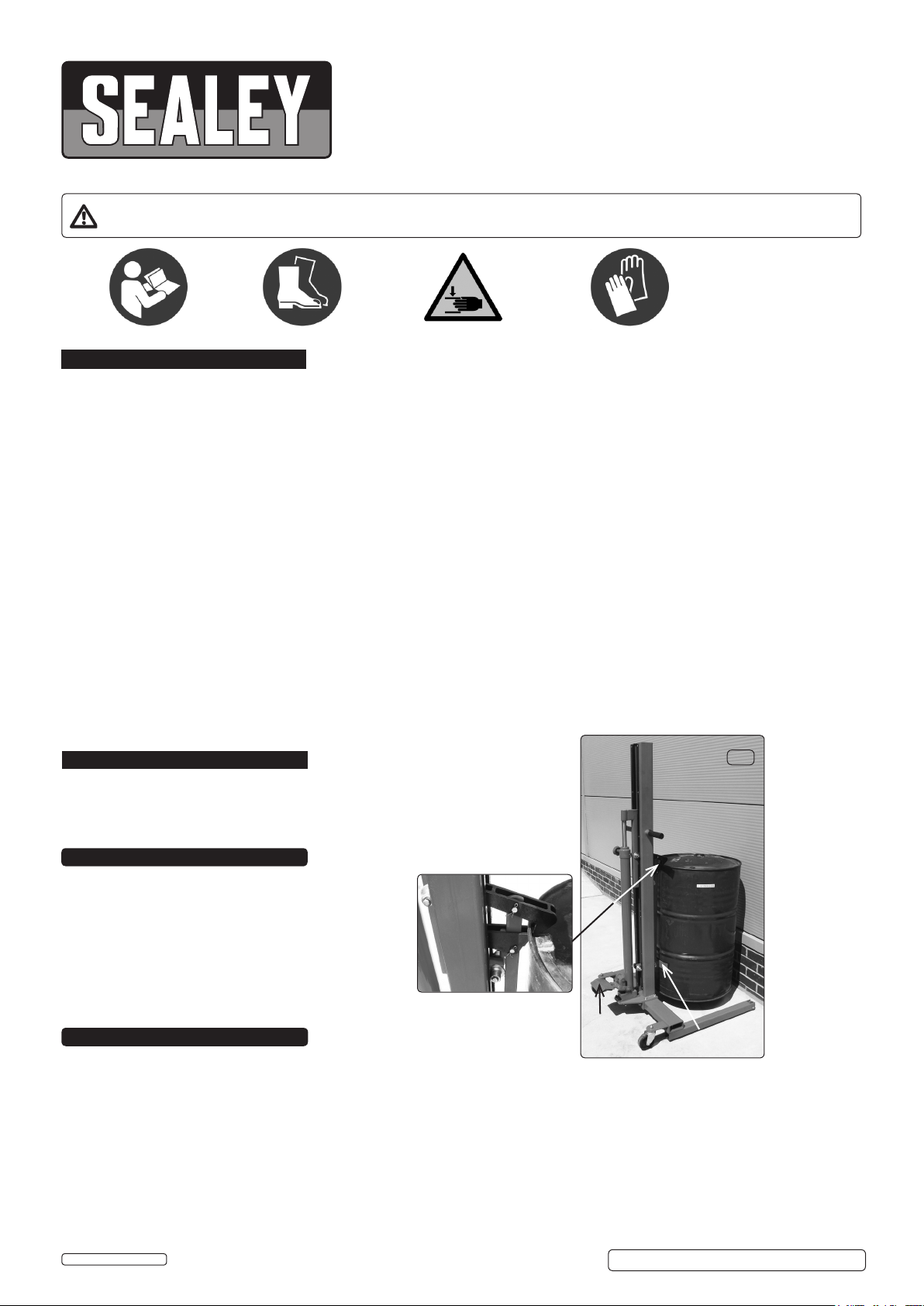
g.1
Ideal for loading and unloading barrel bunds, vans and general drum handling
when forklift is not available. Suitable for 205ltr drums. Foot operated hydraulics,
side handles and smooth-rolling wheels aid handling and manoeuvrability.
3. SPECIFICATIONS
Model: DH03.V2
Maximum Drum Height: 1610mm
Leg Height: 65mm
Leg Length: 590mm
Width Inside Legs: 700mm
Maximum Width: 800mm
Overall Maximum Height: 1950mm
Overall Minimum Height: 1710mm
Weight: 67kg
4. ASSEMBLY
4.1 Frame Assembly
Note! The drum loader is supplied partially assembled requiring minimal assembly. The central vertical column complete with
hydraulics and grab mechanics are pre assembled ready to install on to the base transporter frame.
4.1.1 Removeallcomponents,framemembers,xingsetc.fromthepackingcaseexceptforthecentralcolumn(see4.1.3.).
4.1.2. Fit the base frame legs (71) pre assembled with castors to the box section base frame (69) with the socket head cap screws and spring
washers (70) and (62). Tighten fully and stand the assembled base transporter frame on its castors. Seeg.2.
4.1.3. Lift the central column, to the vertical with gloved hands (two people). Lift either inside the packing case to avoid the column runners,
which are smeared with grease or remove from the packing case.
4.1.4. Bolttheverticalcolumntothebaseframe(g.3)with4setsofM8xings(60)(61)(61)(62)(63).Tightenfully.
4.1.5. Bolttheverticalcolumntothebaseframewith2setsofM12xings(64)(32)(32)(65)(66).Tightenfully.
4.1.6. Fitthetwoplasticgrippedsteelhandles(52)(53)tothetopofthecolumn(g.4)withthetwosocketsetscrews(43).
4.1.7. Closethevalveatthetopofthehydrauliccylinder(g.4)andfootpumptotest,openthevalvetoreturn.
Fulcrum Assembly
(rim grab jaws)
Foot
Pump
Support
Frame
© Jack Sealey Limited
Original Language Version
DH03.V2 Issue No: 2 (HF) - 12/07/18
Page 2
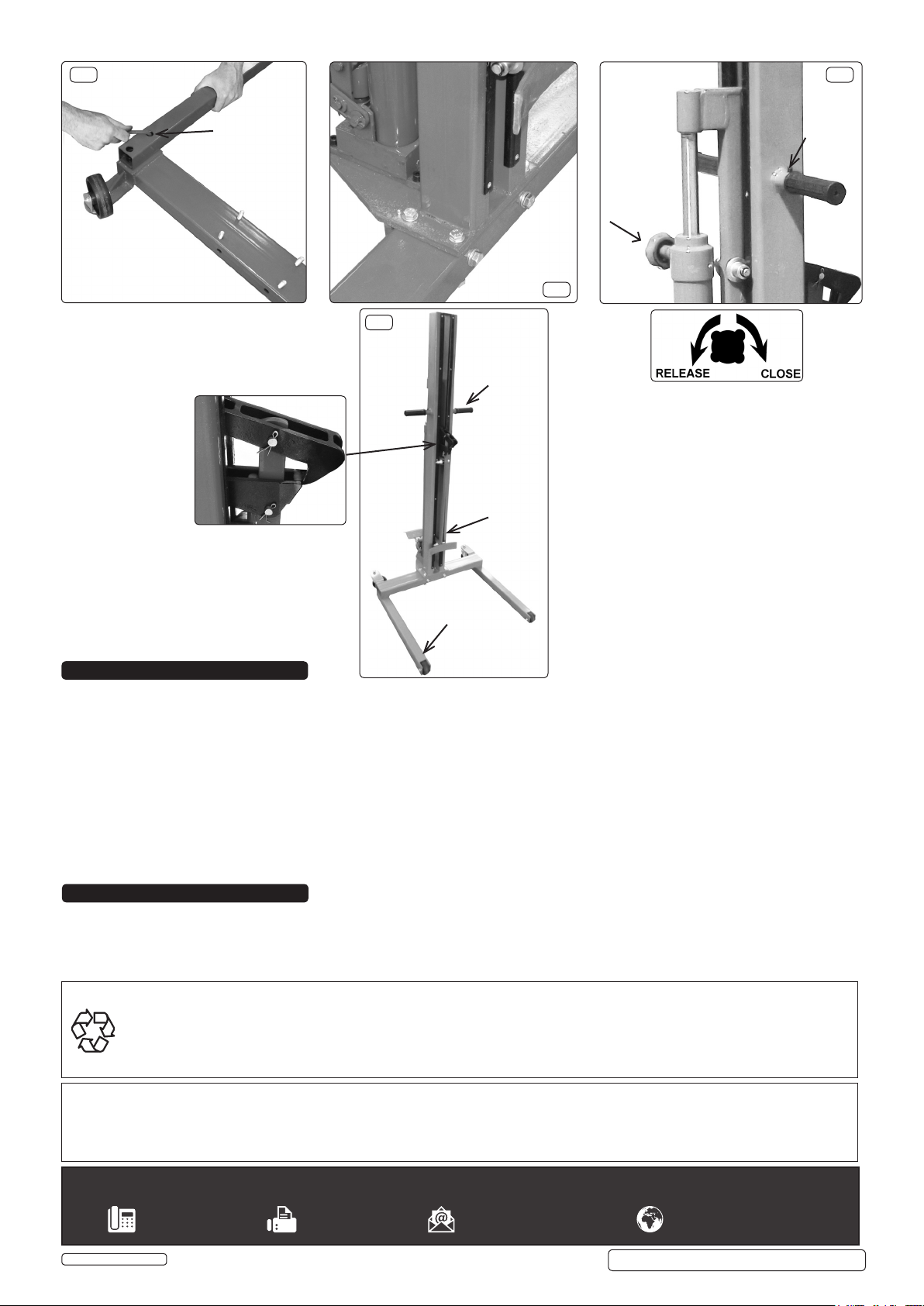
g.2
g.4
Transporter Base Frame
(inverted)
Socket Head
Cap Screw &
Washer
(70) (62)
M8
Fulcrum Jaws
g.5
M8
Handlebars
Column c/w
Hydraulics,
Fulcrum & Drum
Support Frame
M12
g.3
Socket
Set
Screw
(43)
'A'
Viewed On
Arrow 'A'
Transporter
Base Frame
5. OPERATION
5.1 Lifting A Drum
5.1.1. Closethevalve(g.4)fullyclockwise.Footpumptoelevatethefulcrumassemblylowerjawmarginallybelowthedrumrimexternallip
(g.1).
5.1.2. Movethedrumloadertobringthesupportframeyokeintocontactwiththedrum(g.1).Engagethetopjawwiththedrumriminside
diameter; this may require lowering the jaws slightly to obtain the fullest register.
Warning! Ensure that the drum is as low as possible for transporting, elevating only if required at the destination. Ensure there
are no obstacles enroute and the surface is suitable to take the weight of the fully laden drum.
5.1.3. Ensurethatthedrumrimisengagedwiththefulcrumassemblyjaws(g.1).Withbothhandsonthehandlebars,footpumptoraisethe
drum clear of the ground.
5.1.4. Usethehandlebars(g.4)topush,pullandsteerthedrumloader.
5.2. Lowering A Drum
5.2.1. Tolowerthedrumslowly,turnthereleasevalveanticlockwiseinacontrolledmanneruntilthedrumisstandingrmlyontheground.
5.2.2. Release the fulcrum assembly jaws by lifting the top jaw from the drum rim manually and pull the drum loader away from the drum.
6. MAINTENANCE
6.1. Regularly check the drum loader chassis for rigidity including the integrity of the castors.
6.2. Regularly check the fulcrum assembly for wear. Replace worn jaws which may cause poor rim grip.
6.3. Regularly check the linkages and pins for wear or missing retaining split pins which could cause lifting failure.
6.4. Keep the column guides lubricated with grease as supplied. DO NOT contaminate the steering handles with grease.
ENVIRONMENT PROTECTION
Recycle unwanted materials instead of disposing of them as waste. All tools, accessories and packaging should be sorted, taken to
a recycling centre and disposed of in a manner which is compatible with the environment. When the product becomes completely
unserviceable and requires disposal, drain any fluids (if applicable) into approved containers and dispose of the product and fluids
according to local regulations.
Note: It is our policy to continually improve products and as such we reserve the right to alter data, specifications and component parts without
prior notice.
Important: No Liability is accepted for incorrect use of this product.
Warranty: Guarantee is 12 months from purchase date, proof of which is required for any claim.
Sealey Group, Kempson Way, Suffolk Business Park, Bury St Edmunds, Suffolk. IP32 7AR
© Jack Sealey Limited
Original Language Version
DH03.V2 Issue No: 2 (HF) - 12/07/18
 Loading...