

Page 1
INSTRUCTIONS FOR:
BALL JOINT REMOVER COMMERCIAL
Model No: CV012
Thank you for purchasing a Sealey product. Manufactured to a high standard this product will, if used according to these instructions and properly maintained, give
you years of trouble free performance.
IMPORTANT: READ THESE INSTRUCTIONS CAREFULLY. NOTE THE SAFE OPERATIONAL REQUIREMENTS, WARNINGS AND CAUTIONS.
USE THE TOOL CORRECTLY AND WITH CARE FOR THE PURPOSE FOR WHICH IT IS INTENDED. FAILURE TO DO SO MAY CAUSE DAMAGE
AND/OR PERSONAL INJURY AND WILL INVALIDATE THE W ARRANTY. PLEASE KEEP INSTRUCTIONS SAFE FOR FUTURE USE.
1. SAFETY INSTRUCTIONS
WARNING! Ensure Health and Safety, local authority and general
workshop practice regulations are adhered to when using tools.
DO NOT use tools if damaged.
Ensure that a vehicle which has been jacked up is adequately
supported with axle stands and that the wheels are chocked,
refer to the vehicle manufacturer’s service instructions, or a
proprietary manual.
Wear approved eye protection. A full range of personal safety
equipment is available from your Sealey dealer.
Wear suitable clothing to avoid snagging. Do not wear jewellery
and tie back long hair.
DO NOT use air tools to operate the force screw.
Maintain tools in good and clean condition for best and safest
performance.
When not in use, clean and lubricate tool, and store in a safe,
dry, childproof location.
IMPORTANT: This manual is provided as a guide only, refer
to the vehicle manufacturer’s service instructions, or a pro
prietary manual, to establish the current procedure and
data.
WARNING! Failure to heed safety and warning instructions may
result in damage and/or personal injury and will invalidate the
warranty.
WARNING! The warnings, cautions and instructions
refer r e d to in this manual cannot cover all possible
conditions and situations that may occur. It must be
understood that common sense and caution are factors
which cannot be built into this product, but must be
applied by the operator.
DO NOT USE AIR TOOLS
3. OPERATION
The capacity of this tool is 5tonnes.
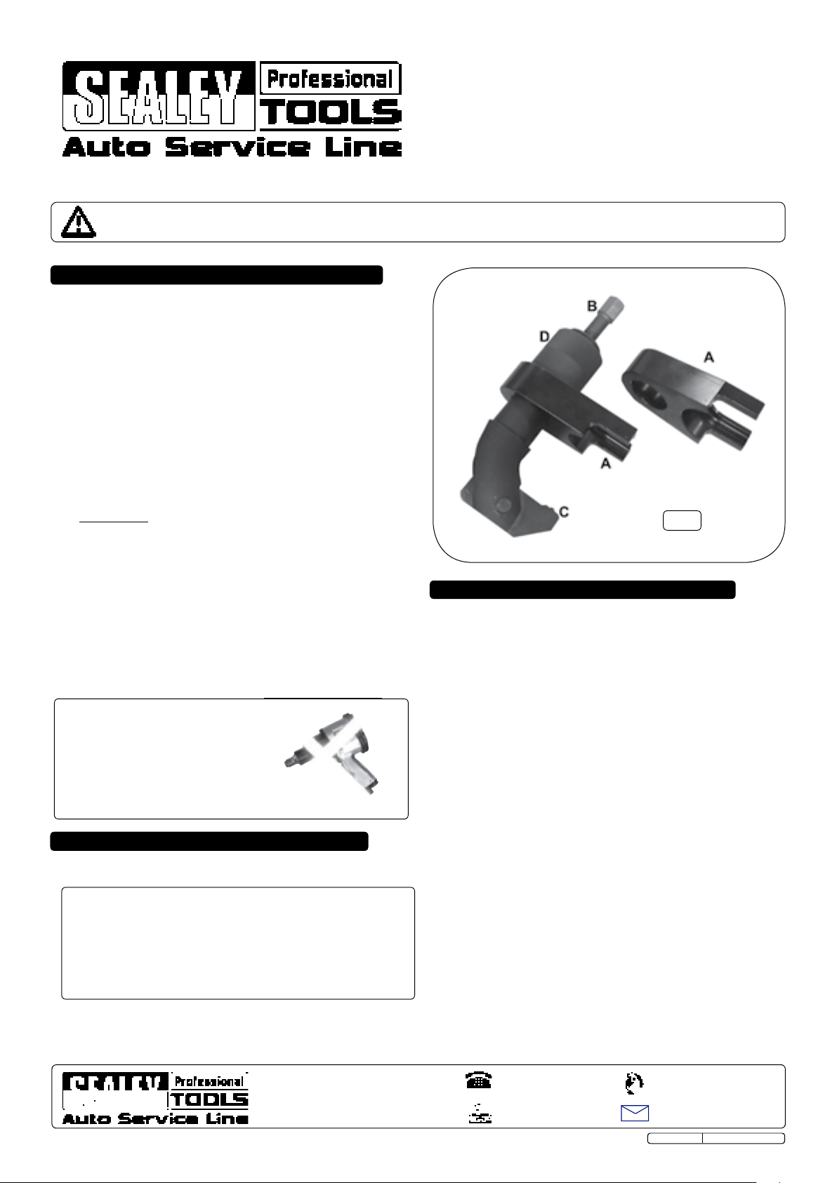
Refer to Fig:1
3.1 Ensure the appropriate sized jaw (A) is used for the
ball joint being worked on.
3.2 Back off the force screw (B) until the pressure lever (C) is at
right angles to the main body.
3.3 Offer up the puller to the ball joint and adjust the jaw adjusting
nut (D) until the tool clamps onto the joint.
3.4 Wind the force screw (B) clockwise until the joint is separated.
3.5 Take the weight of the ball joint splitter and wind back the force
screw (B) anti-clockwise and remove from vehicle.
Fig.1
2. APPLICATIONS / PARTS
• Interchangeable jaws and robust body, designed for the removal
of ball joints fitted to commercial vehicles.
No. Part No. Part name
1 CV012.01 Main Body
2 CV012.02 Jaw (29x80x123L)
3 CV012.03 Jaw (29x64x121L)
4 CV012.04 Pressure lever
5 CV012.05 Pressure lever pin
6 CV012.11 Jaw adjusting nut
NOTE: It is our policy to continually improve products and as such we reserve the right to alter data, specifications and component parts without prior notice.
IMPORTANT: No liability is accepted for incorrect use of this product.
WARRANTY: Guarantee is 12 months from purchase date, proof of which will be required for any claim.
INFORMATION: For a copy of our latest catalogue and promotions call us on 01284 757525 and leave your full name and address, including postcode.
Sole UK Distributor, Sealey Group,
Kempson Way, Suffolk Business Park,
Bury St. Edmunds, Suffolk,
IP32 7AR
©Jack Sealey Ltd Original Language Version
01284 757500
01284 703534
www.sealey.co.uk
Web
sales@sealey.co.uk
email
CV012 Issue: 1 - 18/01/13
 Loading...