

Page 1
INSTRUCTIONS FOR:
AIR HYDRAULIC VEHICLE LIFT 2.5TONNE
MODEL NO: AVR2500A
Thank you for purchasing a Sealey product. Manufactured to a high standard, this product will, if used according to these
instructions, and properly maintained, give you years of trouble free performance.
IMPORTANT: PLEASE READ THESE INSTRUCTIONS CAREFULLY. NOTE THE SAFE OPERATIONAL REQUIREMENTS, WARNINGS & CAUTIONS. USE THE PRODUCT
CORRECTLY AND WITH CARE FOR THE PURPOSE FOR WHICH IT IS INTENDED. FAILURE TO DO SO MAY CAUSE DAMAGE AND/OR PERSONAL INJURY AND WILL
INVALIDATE THE WARRANTY. KEEP THESE INSTRUCTIONS SAFE FOR FUTURE USE.
Read the manual
instructions
Crushing danger
Wear safety
footwear
1. SAFETY
GENERAL SAFETY.
WARNING! Ensure Health & Safety, local authority, and general workshop practice regulations are adhered to when using this equipment.
WARNING! TRAPPING DANGER – Although the vehicle lift movements are slow in operation, keep hands and limbs away from the steelwork
during elevating and lowering. The lowering speed increases during decent and decreases whilst elevating.
Keep the work area clean, uncluttered and ensure there is adequate lighting.
Maintain correct balance and footing. Ensure the floor is not slippery and wear non-slip steel toe capped shoes.
Remove ill-fitting clothes. Remove ties, watches, rings, other loose jewellery.
Familiarise yourself with the applications, limitations and potential hazards of the vehicle lift.
DO NOT use to achieve a task the vehicle lift was not designed to perform.
DO NOT allow untrained persons to assemble or use the vehicle hydraulic lift.
DO NOT lift the vehicle with people inside.
PRE OPERATIONAL SAFETY and *SAFETY FEATURES.
DO NOTexceed the load capacity of 2.5tonne. See your vehicle manual for weight.*In the pump is a calibration valve to prevent lifting
of loads exceeding capacity.
Ensure adequate level space around the vehicle for the operator and the lift.
DO NOT operate the vehicle lift if parts are damaged or missing as this may cause failure and/or personal injury.
Before commencing lift, make a visual inspection of the vehicle lift to ensure there is no sign of damage or loose fixings.
DO NOT use the unit and refer to your local Sealey dealer for advice on replacement parts.
Tighten all hydraulic and pneumatic fittings and ensure hydraulic system is bled and oil level is correct.
Before commencing lift ensure the vehicle bodywork is structurely sound.
Before commencing the vehicle lift apply the vehicle hand brake and leave in first gear. Refer also to section 5.8.1.
*Be aware of an automatic valve on the ram cylinder infeed on the lift which prevents oil spilling out in the event of accidental damage to the
delivery hose.
OPERATIONAL SAFETY.
DO NOT stand on or drive over the hydraulic pump "umbilical" hose or mains air line.
Position the pump, in use, such that there is no tripping hazard. Return the pump to the tray in the base frame when not in use.
After lifting to required working height, ensure that both pawl bars are engaged in a channel notch. Refer to fig.7.
POST OPERATIONAL SAFETY.
When not in use, place the pump back on its tray in the base frame, clean and store the lowered vehicle lift in a safe, dry, childproof location.
Maintain the vehicle lift in good condition. Replace damaged parts. Use genuine parts only. Unauthorised parts may be dangerous and
will invalidate the warranty.
WARNING! The warnings, cautions and instructions in this manual cannot cover all possible conditions and situations that
may occur. It must be understood by the operator that common sense and caution are factors which cannot be built into
this product, but must be applied by the operator.
2. INTRODUCTION
Manoeuvrable low profile lift with retracting wheels for easy positioning under vehicles. Four multi-positioning, height adjustable saddles with
rubber pads. Maximum lift of 1000mm with six height locking positions. Suitable for use with a wide range of vehicles.
3. SPECIFICATION
3.1 Lift specifications
Model No: ............................... AVR2500A
Maximum Load: .............................. 2500kg
Maximum Lift Height: . . . . . . . . . . . . . . . . . . . . . . . . . 1000mm
Min Overall Height: ........................... 125mm
Overall Width:............................... 1600mm
Safety Locking Positions: ............................ 6
Weight: ...................................... 270kg
© Jack Sealey Limited
Original Language Version
AVR2500A Issue: 1 - 07/11/14
Page 2
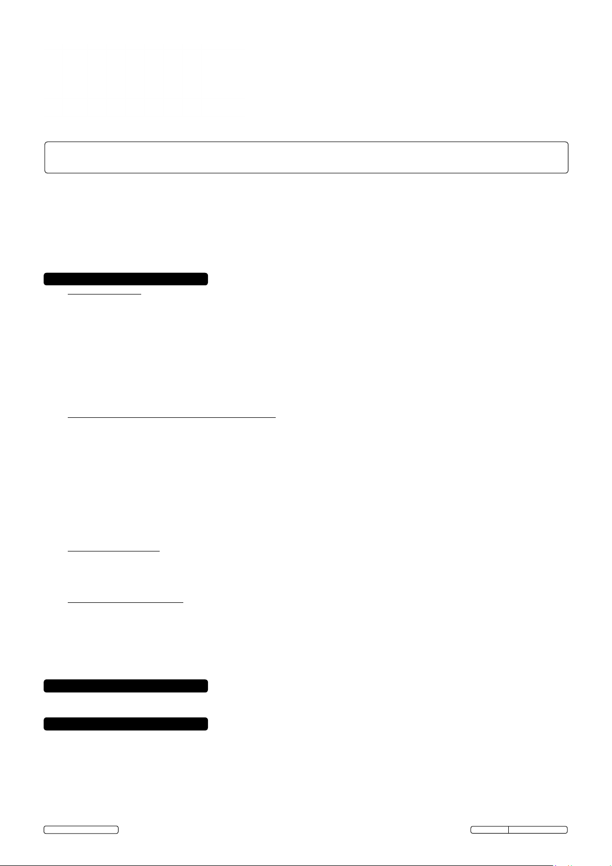
3.2 Lift dimensions
g.1
55
3
500
1000 max
Steps of 100
2550
125
Labelling
Ref Description
1 Data plate
Separate twin
wheeled carriage
Ø120
140 min
2 Liting Capacity 2500kg
3 Serial number
1600 max
1170 min
Pad sweep radius
120 min
292 max
1200 max
3.3 Vehicle weight distribution
3.3.1. Weight of the vehicle must not exceed 2500kg.
3.3.2. Vehicle acceptable weight distribution 2:3 or 3:2 reversible.
3.3.3. Lifting from the side of a vehicle is not recommended. Weight distribution will require careful assessment by the user.
1
2
g.2
2500kg max
3.4 Required work surface
3.4.1. Lift bearing area must be 1500mm x 2600mm minimum, level and flat within 5mm, without steps.
3.4.2. The lift area must be suitable for the load; concrete preferred. DO NOT site on tar macadum.
g.3
2500kg max
2500kg max
Preferred lifting orientation 1.
© Jack Sealey Limited
Original Language Version
Preferred lifting orientation 2.
AVR2500A Issue: 1 - 07/11/14
Page 3

4. CONTENTS
4.1. Assembly
4.1.1. The major structural components including the hydraulic ram are pre-assembled, requiring only attachments. Use the
picture below to check all parts are present.
4.1.2. A separate twin wheeled carriage enables transporting the lowered assembled vehicle lift. This carriage is also used for
removing compression springs from the base frame sprung loaded castors. Refer to section 5.8.2 and 5.8.3.
4.1.3. See the 'Maintenance' section for air line and hydraulic line circuit connections.
g.4
Site pump here
Pawl disengage rail
Adjustable longitudinally
Front transit point twin wheel carriage
"H" = 500
"H" = 1000
Assembly shown full height
Ensure the pin enters
a graduated pin hole
in the quadrant plate
Jacking point for castor
compression spring removal
© Jack Sealey Limited
Sprung loaded transit castor
and spring retainer cup
Original Language Version
Support pad swivel
(xed longitudinally)
AVR2500A Issue: 1 - 07/11/14
Page 4

5. OPERATION
5.1. Ensure the air supply valve is in the "Off" position (fig.5) before connecting to the air supply. The air/hydraulic lift requires a minimum
air pressure of 6-7bar to operate. Mains air supply, suggested minimums, 200ltr compressor and 1/2" pipework.
WARNING! Ensure the air supply is clean and does not exceed 7bar). Too high an air pressure and unclean air will
shorten the life of the unit due to excessive wear, and may be dangerous causing possible damage and/or personal injury.
5.2. Drain the air supply tank daily and clean the air
inlet filter screen weekly.
5.3. For recommended supply, see diagram (fig.5) to right.
5.4. Line pressure should be increased to compensate for
unusually long air hoses (over 8 metres).
5.5. Keep hose away from heat, oil and sharp edges.
Check hoses for wear and make certain that all
connections are secure.
WARNING! In an emergency, if a shut off valve is
not available in the mains air supply line, disconnection of the air line from the pump would achieve the same result.
5.6. Operating the pump (fig.6)
5.6.1. Elevate by depressing the pump pedal position "A" and hold.
5.6.2. Park the lift at any pawl prop notched height by removing the foot from the pump with a bias toward position "B". See fig.7 and
note 5.8.7.
5.6.3. Control descent by briefly depressing the pump pedal position "A", to enable pawl prop disengagement, followed by fully depressing
pump pedal position "B", depressing valve "C" and hold. See fig.6.
g.5
SHUT OFF
VALV E
"B"
"C"
g.6
"A"
"Operater present" pump
5.7. Test run
5.7.1. Before each use, check the vehicle lift is functioning correctly and ensure it is not damaged or worn.
5.7.2. With the air line connected operate the lift valve pedal to trial elevate, release the valve to stop. Lower the lift by operating the
hydraulic release valve pedal. It will only elevate or descend whilst the pedal is being operated ("Operater present" system).
5.8. Lifting the vehicle
5.8.1. Lock, chock and handbrake vehicle wheels as required. Remove any objects left on the boot lid, bonnet and roof.
5.8.2. The vehicle lift assembly is mounted on two sprung loaded castors at one end for transit. Manouevrability is obtained by inserting the
pin of the twin wheeled carriage, as shown in fig.1 at the opposite end. Partially elevate the frame with the twin wheeled carriage lever
and position beneath the vehicle as shown in fig.2 and fig.3.
5.8.3 Remove the two compression springs by elevating the frame with the twin wheeled carriage lever at the sprung loaded castor end.
This will remove the compression spring forces, allowing removal from the castor bracket and placing them into the retaining cups.
5.8.4. With the fully lowered frame centrally positioned beneath the vehicle, locate the support pads on to their respective swivel arms and
decide on safe and mechanically stable areas for lift.
5.8.5. "Inch" elevate the lift with the foot pedal and rotate the pads anticlockwise to contact the vehicle, ensuring the pin enters a graduated
pin hole in the quadrant plate of the swivel arm (fig.4). This will prevent unexpected movement of the load.
5.8.6. With the air line connected, operate the lift valve pedal to trial elevate, release the valve to stop if required.
5.8.7. Continue to elevate, observing the pivotting pawl props. Notches in the base frame govern fixed height "parking stations". The first
"parking station" represents an elevated height of 500mm; although distances vary between notches they each represent a 100mm
graduated step in elevated lift. Release the pump foot pedal at the required "parking station" notch, and allow both prop arms to
engage with the notch (fig.7). Lower the lift by operating the hydraulic release valve pedal, until the prop engages with the notch edge.
5.8.8. Lower the lift by operating the foot pedal; this action operates a 3 port 2 position pneumatic valve. Two small pneumatic cylinders in
the area of the pump utility tray, rotate the pawl prop guide rails, lifting the props out of the "parking station" notches. See fig.7, fig.4
and pneumatic circuit fig.8. Control descent by briefly depressing the pump pedal position "A" (fig.6), to enable pawl prop
disengagement, followed by fully depressing pump pedal position "B"(fig.6), depressing valve "C"(fig.6) and hold.
© Jack Sealey Limited
g.7
Ascending
Descending
Path of pawl follower
Path of pawl follower
Original Language Version
Engagement with
"parking station" notch
Disengagement with
"parking station" notch
AVR2500A Issue: 1 - 07/11/14
Page 5

6. TROUBLESHOOTING
PROBLEM CAUSE REMEDY
Lift does not elevate Mains air at 6bar to 7bar not connected. Check connection and available air pressure
Low oil level Add oil. (5litre capacity tank)
Hydraulic system not primed correctly Operate the foot pedal in "RELEASE" mode
Oil lter blocked Clean or replace
and the air valve at the same time to start the
pump.
Contact your Sealey Dealer when above
remedies do not resolve the problem. DO
NOT attempt to service hydraulic pump
module.
Hydraulic hose accidentally punctured or
crushed by an external load.
Replace the hose and bleed entire system.
Remove the external load.
Lift elevates unevenly. Tank not vented. Vent the tank using the vent screw on the
cap.
Lift descends as soon as elevating action
ceases.
Air in hydraulic system. Operate the foot pedal in "RELEASE" mode
and the air valve at the same time to start the
pump.
Pump seal faulty Contact your Sealey Dealer. DO NOT attempt
to service hydraulic pump module.
Lift fails to lower. Pawl prop has not disengaged from parking
station.
Check the pawl lift cylinders are operating.
Check the mechanism, repair if required. Test
valve function item "C" in g.6.
Insufcient load on the lift. Choose a safe method of increasing the load.
3 port 2 position valve malfunction. Replace the valve after rst isolating the
mains air supply.
Obstacle beneath the lift. Raise the load until the pawl props register
with the nearest notch, making it safe to
remove the obstacle.
IMPORTANT: NO RESPONSIBILITY IS ACCEPTED FOR INCORRECT USE OF THIS PRODUCT.
Hydraulic products are only repaired by local service agents. We have service/repair agents in all parts of the UK.
DO NOT RETURN THE PRODUCT TO US. Please telephone us on 01284 757500 to obtain the address and phone number of your local
agent. If product is under guarantee please contact your dealer.
De-commissioning product
Should the product become completely unserviceable and require disposal, draw off the oil into an approved container and dispose of the
product and the oil according to local regulations. See also 'Environmental Protection'.
7. MAINTENANCE
7.1. Before each use, check the vehicle lift to ensure it is not damaged or worn. If in any doubt DO NOT use the unit. Remove it from
service immediately and contact your local Sealey dealer for advice/repairs.
7.2. Refilling the hydraulic system with oil is rarely necessary but the level should be checked in the event of a loss of performance. To
check oil level, ensure the ram is fully lowered, remove filler plug and check that level is within10mm of filler hole. Add
jack oil, such as SEALEY HYDRAULIC JACK OIL.
7.3.
Change the oil every 100 working hours.
WARNING: DO NOT use brake fluid, or any fluid other than hydraulic jack oil as this will cause serious damage to the jack
and will invalidate the warranty!
7.2. Pneumatic circuit (fig.8)
7.2.1. See section 5.6
7.2.2. The two cylinders are mounted adjacent to the hydraulic pump stowage tray on the main frame. They are actuated by the foot pedal
on the hydraulic unit. See 5.8.8.
g.8
Pawl lift
cylinders
3/2
Valve
MAINS
AIR
a good quality
© Jack Sealey Limited
Original Language Version
AVR2500A Issue: 1 - 07/11/14
Page 6

7.3. Hydraulic circuit (fig.9)
7.3.1. Connect the cylinder tubing (1) to the delivery tube and connect the "back to tank" tube (2) to the recovery tube.
7.3.2. With mains air 'ON' (see the pneumatic circuit fig.8 and fig.5), raise and lower a few times to remove air from the hydraulic circuit. For
lowering, a load will be required to exhaust the oil "back to tank".
Hydraulic Cylinder
Load
R
2
1
g.9
g.10
Q
L
E
A
G
P
2
"Return
to tank"
R
M
B
N
F
D
C
H
A
I
1
O
Supply
Reference Description
A Tank
B Pressure relief valve 250bar (29,000 kPa)
C Oil lter
D Pump valve
E Silencer
F Pump
G 3 port 2 position vavle
H Air lter
I Air line adaptor
L Control valve (lower lift)
M Delivery v alve
N Control valve (elevate lift)
O Air actuated hydraulic pump assembly
P Pawl lift pneumatic cylinders
Q "Parachute" valve (tube rupture)
R Hydraulic cylinder (ram)
Environmental Protection
Recycle unwanted materials instead of disposing of them as waste. All tools, accessories and packaging should be
sorted, taken to a recycling centre and disposed of in a manner which is compatible with the environment.
When the product becomes completely unserviceable and requires disposal, drain off any fluids (if applicable)
into approved containers and dispose of the product and the fluids according to local regulations.
Parts support is available for this product. To obtain a parts listing and/or diagram, please log on to
www.sealey.co.uk, email sales@sealey.co.uk or phone 01284 757500.
NOTE: It is our policy to continually improve products and as such we reserve the right to alter data, specifications and component parts without prior
notice.
IMPORTANT: No liability is accepted for incorrect use of this product.
WARRANTY: Guarantee is 12 months from purchase date, proof of which will be required for any claim.
© Jack Sealey Limited
Sole UK Distributor, Sealey Group,
Kempson Way, Suffolk Business Park,
Bury St. Edmunds, Suffolk,
IP32 7AR
Original Language Version
01284 757500
01284 703534
www.sealey.co.uk
sales@sealey.co.uk
AVR2500A Issue: 1 - 07/11/14
 Loading...