

Page 1
INSTRUCTIONS FOR
MPORTANT:
PLEASE READ THESE INSTRUCTIONS CAREFULLY. NOTE THE SAFE OPERATIONAL REQUIREMENTS, WARNINGS & CAUTIONS. USE
THE PRODUCT CORRECTLY AND WITH CARE FOR THE PURPOSE FOR WHICH IT IS INTENDED. FAILURE TO DO SO MAY CAUSE DAMAGE AND/OR
PERSONAL INJURY AND WILL INVALIDATE THE WARRANTY. KEEP THESE INSTRUCTIONS SAFE FOR FUTURE USE.
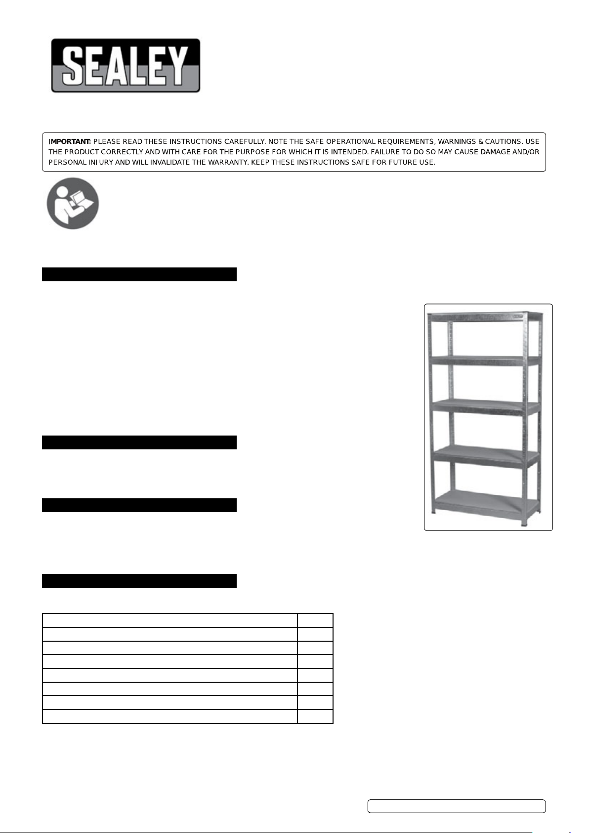
DESCRIPTION. RACKING UNIT WITH 5 SHELVES
(150KG CAPACITY PER LEVEL)
MODEL NO: AP6150 & AP6150GS
Thank you for purchasing a Sealey product. Manufactured to a high standard, this product will, if used according to these
instructions, and properly maintained, give you years of trouble free performance.
Refer to
instructions
1. SAFETY
WARNING! Ensure Health & Safety, and local authority regulations are adhered to when assembling and using this rack.
9 Locate rack in a suitable area where it will not be an obstruction.
9 Keep the general area clean, uncluttered and ensure there is adequate lighting.
WARNING! Erect rack on a level and solid surface such as concrete.
9 Keep children and unauthorised persons away from the storage area.
8 DO NOT use the rack for any purpose other than that for which it is are designed.
8 DO NOT site the rack out of doors.
8 DO NOT get the rack wet or use in damp or wet locations or areas where there is condensation.
8 DO NOT clean the shelf supports with any solvents which may damage the surface.
9 Ensure that the rack is properly assembled before loading them with heavy items.
WARNING! Maximum load for each shelf is 150kg.
9 Where possible the rack should be fixed to the wall with suitable fixings
9 Place heavier items on the lower shelves.
9 Heavier items should be evenly distributed across the shelves.
2. INTRODUCTION
Steel frame with five MDF shelves (AP6350 painted/AP6350GL galvanised). 150kg capacity per level giving
a maximum capacity of 750kg per rack. No nuts and bolts means no tools required to assemble. Clips
together in minutes. Two piece uprights allow use as a single bay rack, or split in two separate shelf
systems or workstations.
3. SPECIFICATION
Model No..............................AP6150..............................AP6150GS
Coating......................................Paint.............................Galvanised
Height..................................1805mm.................................1805mm
Width.....................................810mm...................................810mm
Depth.....................................310mm...................................310mm
4. CONTENTS
Carefully unpack the product and check the contents against the list below. Should any items be missing or damaged make immediate
contact with your Sealey dealer.
Part Description No. off
Leg Angle Section 8
Leg Angle Joiners 8
Plastic Floor Protectors 8
Shelf Support, Long 10
Shelf Support, Short 10
MDF Shelf 5
Fastener Kit (Nuts & Bolts for joining side by side sections) 4
© Jack Sealey Limited
Original Language Version
AP6150, AP6150GS | Issue 2 17/08/16
Page 2

5. ASSEMBLY
5.1. Assemble the frame using a soft faced hammer or mallet as shown
in fig.1. If only a hard faced hammer is available hammer onto a
piece of wood to avoid damaging the paint surface. Always hammer
gently as close as possible to the uprights. Make sure that the shelf
support tabs are in line with the leg angle slots. If the tabs and slots
are not lining up do not use force as this may damage the tabs. If the
tabs are out of line bend them slightly to line up with the slots.
5.2. See fig.1. Decide on the position/height of the bottom shelf.
Make an end frame by fitting 1 short shelf support between 2 leg
angle sections. Make a second end frame ensuring that the shelf
support is at the same height as the first end frame. Join the two
end frames together using 2 long shelf supports fixed at the
same height as the short shelf supports.
5.3. See fig.2. Decide on the height of the second shelf. Fit another
2 short shelf supports at the desired height then fit 2 long shelf
supports at the same height.
g.1
5.4. Decide the shelf positions for the upper section of the shelves
and assemble two more end frames, each using 2 leg angle
sections and 3 short shelf supports ensuring that the shelf supports
are at the same height on both frames. The upper half can be joined
to the lower half by using the lower shelf supports as shown in fig.3.
If the lower shelf is not positioned at the centre of the frame use the
special joining pieces supplied as shown in fig.4.
5.5. When both upper end frames are in place join them together with the
remaining 6 long shelf supports ensuring that they are at the same
height as the short shelf supports.
g.2
g.3
© Jack Sealey Limited
Original Language Version
AP6150, AP6150GS | Issue 2 17/08/16
Page 3

5.6. See fig.5. When the frame is complete attach the plastic floor
protectors to the bottoms of the angle sections. Get a second
person to steady the frame while this is done.
5.7. See fig.6. Move the frame into position in the chosen area.
Place the 5 MDF shelves onto the shelf supports.
5.8. See fig.7. To assemble as a bench/low level shelving unit make
up two separate frames following steps 4.1 to 4.3 but with different
shelving positions. Make up one frame with 3 shelves and one
frame with two shelves as shown below. Ensure that the middle
and top shelves on both frames are at the same height.
Fix the frames together with the four nuts and bolts supplied.
Place the 5 MDF shelves into position in the frames.
g.4
g.5
g.6
g.7
5.9. See fig.8. To assemble as a corner unit make up two separate
frames following steps 4.1 to 4.3 but with different shelving
positions. Make up one frame with 3 shelves and one frame with
two shelves as shown below. Ensure that the middle and top shelves
on both frames are at the same height. Fix the frames together with
the four nuts and bolts supplied. Place the 5 MDF shelves into
position in the frames.
g.8
NOTE: It is our policy to continually improve products and as such we reserve the right to alter data, specications and component parts without prior notice.
IMPORTANT: No liability is accepted for incorrect use of this product.
WARRANTY: Guarantee is 12 months from purchase date, proof of which will be required for any claim.
Sole UK Distributor, Sealey Group.
Kempson Way, Suffolk Business Park,
Bury St.Edmunds, Suffolk.
IP32 7AR
01284 757500
01284 703534
www.sealey.co.uk
sales@sealey.co.uk
© Jack Sealey Limited
Original Language Version
AP6150, AP6150GS | Issue 2 17/08/16
 Loading...