

Page 1
INSTRUCTIONS FOR:
HEAVY-DUTY WORKBENCH WITH 2 DRAWERS
MODEL: AP2020
Thank you for purchasing a Sealey product. Manufactured to a high standard this product will, if used according to these instructions and
properly maintained, give you years of trouble free performance.
IMPORTANT: PLEASE READ THESE INSTRUCTIONS CAREFULLY. NOTE THE SAFE OPERATIONAL REQUIREMENTS, WARNINGS & CAUTIONS.
USE THE PRODUCT CORRECTLY AND WITH CARE FOR THE PURPOSE FOR WHICH IT IS INTENDED. FAILURE TO DO SO MAY CAUSE
DAMAGE OR PERSONAL
INJURY, AND WILL INVALIDATE THE WARRANTY. PLEASE KEEP INSTRUCTIONS SAFE FOR FUTURE USE.
1. SAFETY INSTRUCTIONS
1.1 GENERAL SAFETY
p WARNING! Ensure Health & Safety, local authority, and general workshop practice
regulations are adhered to when using this bench.
3 Locate bench in a suitable working area.
3 Keep the work area clean, uncluttered and ensure there is adequate lighting.
p WARNING! Use bench on level and solid ground, preferably concrete. Avoid tarmacadam
since the bench may sink into the surface.
3 Keep the bench clean and tidy in accordance with good workshop practice.
3 Keep children and unauthorised persons away from the working area.
7 DO NOT use the bench for any purpose other than that for which it is designed.
7 DO NOT undertake work on the bench without the workpiece being adequately secured. Use
clamps or a vice (not included) to secure the workpiece. Available from your Sealey dealer.
7 DO NOT use the bench out of doors.
7 DO NOT get the bench wet or use in damp or wet locations or areas where there is
condensation.
7 DO NOT clean the bench with any solvents which may damage the paint surface or the
protective coating on the wooden top.
p Maximum weight for each drawer is 25 kg, full load for Workbench is 250 kg
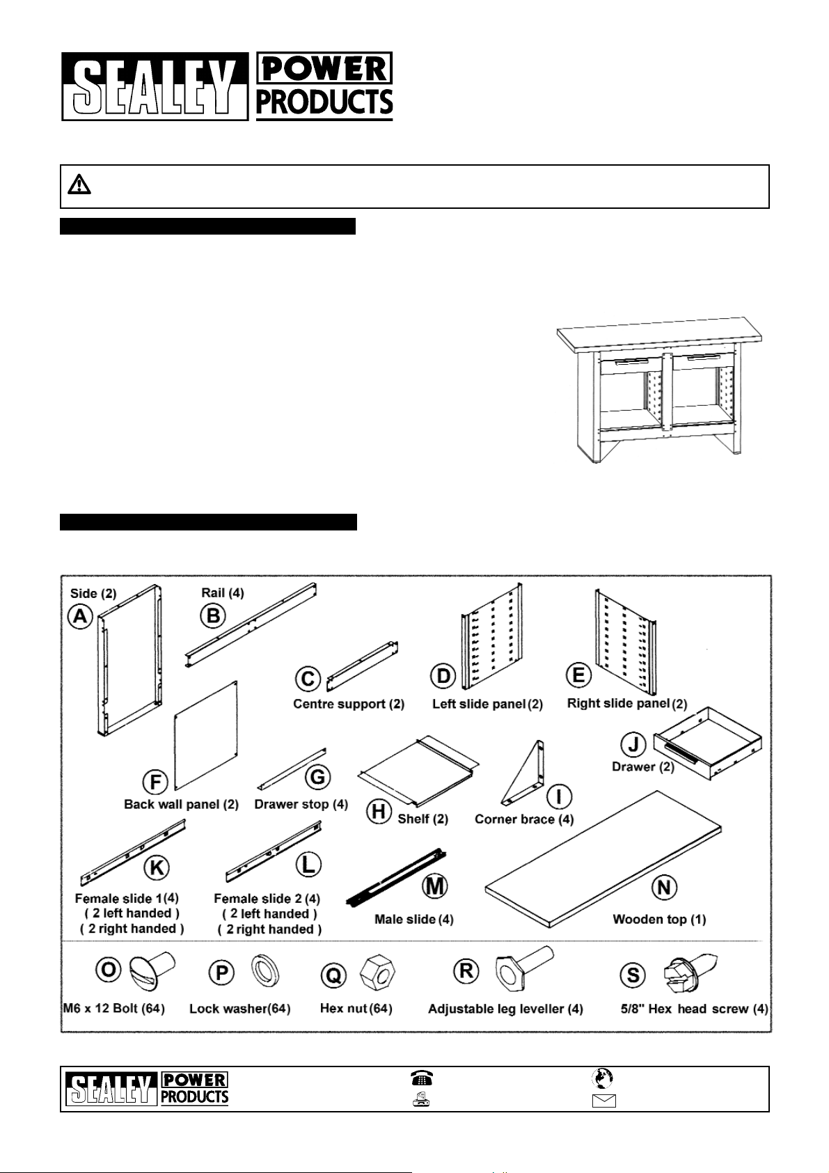
2. CONTENTS
2.1 Carefully unpack the product and check the contents against the diagram below. Should any items be missing or damaged make
immediate contact with your Sealey dealer.
Sole UK Distributor
Sealey Group,
Bury St. Edmunds, Suffolk.
01284 757500
01284 703534
www.sealey.co.uk
b
e
W
sales@sealey.co.uk
email
AP2020 - 1 - 061005
Page 2
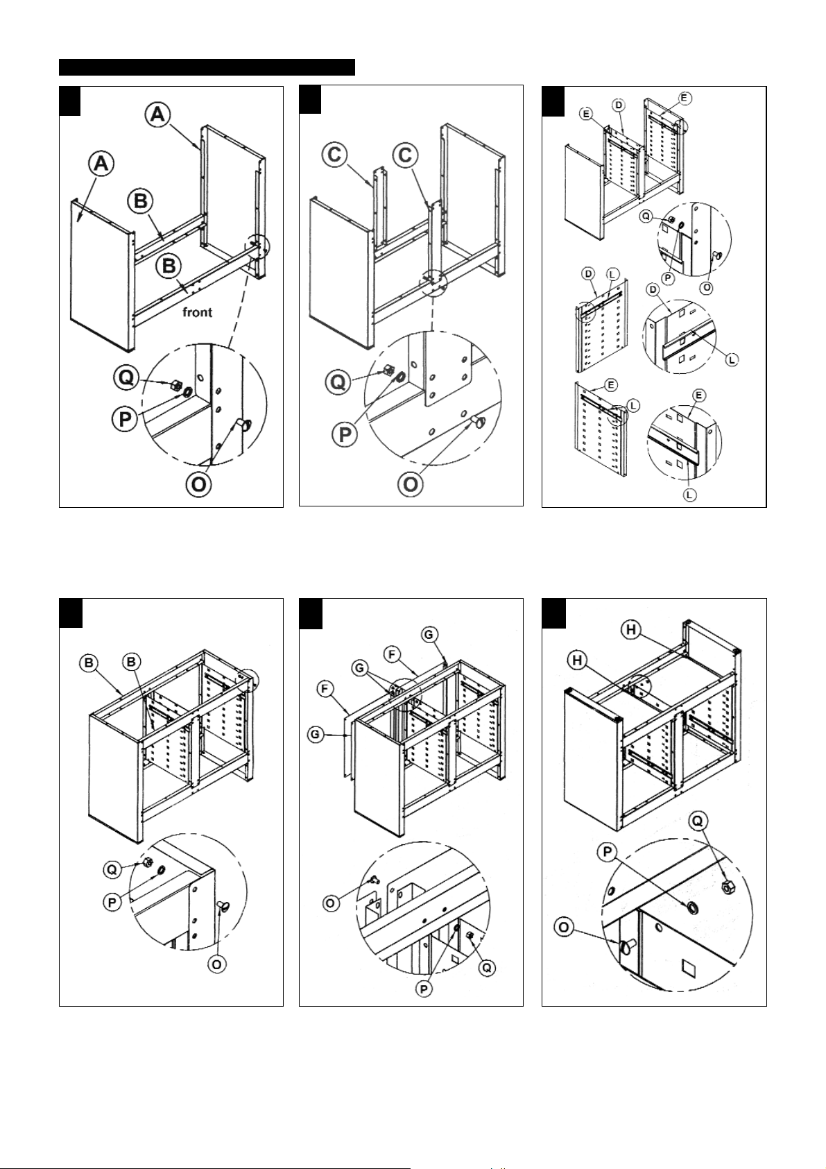
3. ASSEMBLY
1
2
3
STEP 1. Take two crossrails (B) and bolt them
to the cabinet sides (A) using 8 bolts (O), 8 lock
washers (P), and 8 nuts (Q). Ensure that the
pairs of holes that accept the corner braces are
facing downwards. (Refer to STEP 7.)
4
STEP 2. Bolt the two centre supports (C) to the
front and back crossrails respectively using 4
bolts (O), 4 lock washers (P), and 4 nuts (Q).
5
STEP 3. Bolt 2 left & 2 right slide panels (D) &
(E) into position, only bolt at front of Work
Bench using 8 bolts (O), 8 lock washers (P),
and 8 nuts (Q). Fix 1 left hand female slide (L),
at top onto each slide panel (D) and 1 right
hand female slide (L), onto each slide panel (E)
Refer to Diagram 11 on how to fit slides.
6
STEP 4. Take two crossrails (B) and bolt them
to the cabinet sides (A) and centre supports (C)
using 12 bolts (O), 12 lock washers (P), and 12
nuts (Q).
STEP 5. T
panel (F) and bolt them to the back of the
cabinet with the draw stop
and the cabinet. Repeat procedure with the
other back p
(O), 8 lock washers (P), and 8 nut
ake two draw stop
anel and 2 draw stop
s (G) and one back
s between the p
s. Use 8 bolt
s (Q).
anel
urn the cabinet up
STEP6.
the two shelf component
the bottom of the unit using 8 bolt
washers(P), and 8 nut
s
T
side down and bolt
into position at
s (H)
s (Q).
AP2020 - 1 - 061005
s (O), 8 lock
Page 3

7
STEP 7. Screw in the four adjustable leg
levellers (R). Bolt the four corner braces (I) into
position using 16 bolts (O), 16 lock washers
(P), and 16 nuts (Q)
8
STEP 8. Place the wooden top (N) face down
on a flat, clean, smooth surface. Position the
cabinet upside down on the wooden top and
mark the hole locations on the top. Move the
cabinet to one side and drill 5/32 diameter x
1/2 deep holes in the top. DO NOT DRILL
DEEPER THAN 1/2. Attach frame to top with
the 4 hex head screws (S).
9
STEP 9. Take the 4 male slide components (M)
and slide 2 onto the female slides on the left of
the draw compartment and 2 onto the female
slides on the right hand side of the draw
compartment. Push them fully in to engage
them, then pull them out to the stop point.
10 11
STEP 10. Attach a left hand female slide (K) to
left hand side of each draw and a right hand
female slide (K) to the right hand side of each
draw (see diagram 11). Engage each draw onto
the protruding male slides and push fully home,
then open the draw to check that it is retained.
Diagram 11. Orientate each slide as shown in the diagram above with the rear hook pointing
towards the rear of the draw or the rear of the cabinet. Put the rear hook on each slide into the
square hole nearest the back of the draw or the back of the cabinet and push the slide backwards
to engage the hook. Swivel the front of the slide up or down slightly until the other two hooks appear
in the other two holes. Keep the rear face of the slide up against the draw or slide panel. On the
draws pull the slide sharply upwards to engage it. On the cabinet push the slides down to engage.
AP2020 - 1 - 061005
 Loading...