

Page 1
INSTRUCTIONS FOR:
WOODWORKING BENCH 1.52
mtr
MODEL: AP1520
Thank you for purchasing a Sealey product. Manufactured to a high standard this product will, if used according to these instructions and
properly maintained, give you years of trouble free performance.
1. SAFETY INSTRUCTIONS
IMPORTANT: PLEASE READ THESE INSTRUCTIONS CAREFULLY. NOTE THE SAFE OPERATIONAL REQUIREMENTS, WARNINGS & CAUTIONS.
USE THE PRODUCT CORRECTLY AND WITH CARE FOR THE PURPOSE FOR WHICH IT IS INTENDED. FAILURE TO DO SO MAY CAUSE
DAMAGE OR PERSONAL INJURY, AND WILL INVALIDATE THE WARRANTY. PLEASE KEEP INSTRUCTIONS SAFE FOR FUTURE USE.
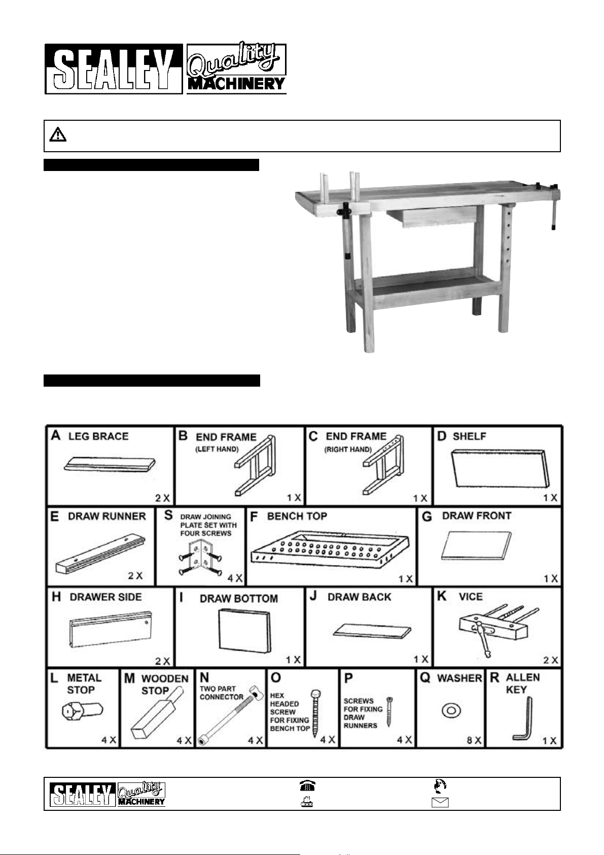
2. CONTENTS
1.1 GENERAL SAFETY
! WARNING! Ensure Health & Safety, local authority, and general
workshop practice regulations are adhered to when using this
bench.
" Locate bench in a suitable working area.
" Keep the work area clean, uncluttered and ensure there is adequate lighting.
! WARNING! Use bench on level and solid floor surface.
" Keep the bench clean and tidy in accordance with good workshop practice.
" Keep children and unauthorised persons away from the working area.
# DO NOT use the bench for any purpose other than that for which it is
designed.
# DO NOT undertake work on the bench without the workpiece being
adequately secured.
# DO NOT use the bench out of doors.
# DO NOT get the bench wet or use in damp or wet locations or areas where
there is condensation.
# DO NOT clean the bench with any solvents which may damage the paint
surface or the protective coating on the wooden top.
AP1520 - 1 - 14/09/06
2.1 Carefully unpack the product and check the contents against the diagram below. Should any items be missing or damaged make
immediate contact with your Sealey dealer.
01284 757500
01284 703534
sales@sealey.co.uk
Sole UK Distributor
Sealey Group,
Bury St. Edmunds, Suffolk.
www.sealey.co.uk
Web
email
Page 2

AP1520 - 1 - 14/09/06
3. ASSEMBLY
3.1 Take the 4 short rods from the two part connectors (N) and insert one into each hole at either end of the leg braces (A) as shown in
fig.1. Each rod has a screwdriver slot in one end. Use this slot to rotate each rod so that the slot is in line with the overall length of the
leg brace.
3.2 Take the lefthand end frame (B) and join it to the righthand end frame (C) using one of the cross braces (A) as shown in fig.2. Insert
a long socket cap bolt from the two part connector (N) through each end frame and into the leg brace. Using the 6mm Allen Key
provided rotate each bolt so that it picks up the threaded hole through the short rod. Continue to rotate until the end frame pulls up
tight against the end of the leg brace.
3.3 Take the shelf (D) and position it between the end frames so that its lower edge fits into the slot on the inside face of the first leg
brace as indicated in fig.3. Take the other leg brace (A) and place it into position between the end frames so that the edge of the shelf
fits into the slot on the inside face of the leg brace. Retain the leg brace with the remaining long socket cap bolts as shown in fig.4.
3.4 Spread some protective material on the floor (e.g. packaging cardboard) and place the bench top (F) face down on the material.
Attach the two draw runners (E) to the underside of the bench top in the positions shown in fig.5 using the four screws (P).
3.5 Turn the end frame/shelf assembly upside down and place it on top of the bench top in the position shown in fig.5. Fix it down using
the four large hex headed screws (O) and four washers (Q) provided.
Page 3

AP1520 - 1 - 14/09/06
4. WOODWORKING
3.6 To assemble the draw, first take the two draw sides (H) and place them down on a flat surface ready to attach the joining brackets.
The two draw sides are handed. The dowels that protrude from the outside faces of the sides should be placed downwards and the
slots for the bottom of the draw should be facing upwards and be close to each other as shown in fig.6. Now attach the joining
brackets as shown using the pre-drilled holes and screws provided.
3.7 Attach the draw back (J) to the sides as shown above (centre) ensuring that the slot on the inside face is aligned with slots on the
inside faces of the side pieces. Slide the draw bottom (I) into place.
3.8 Lay the draw front (G) face down as shown above (right) and place the assembled draw onto it so that the joining brackets are
aligned with the pre-drilled holes. Fix in place with the remaining screws.
3.9 Place the assembled draw onto the draw runners and slide into position as shown below.
3.10 Attach the two vices (K) by inserting the three rods on each into the holes in the sides of the bench top (fig.7). Now rotate the vice
handle so that the central threaded rod engages with the threaded casting on the inside face of the bench top, and continue rotating
until the vice is closed.
4.1 If you have no experience of good woodworking practice you should seek instruction from a qualified source. The following list covers
some of the basics but should not be regarded as complete.
4.2 Tools should be well maintained and regularly sharpened. Sharpening tools successfully is a skill that has to be practiced.
4.3 Tools with exposed cutting edges such as chisels should be used in a controlled manner to avoid cutting accidents.
4.4 Where considerable force is required to use a tool (such as hitting a chisel with a mallet) the tool should be held in such a way that the
sudden release of the force can be controlled to avoid accidents e.g. when a chisel or drill breaks through the material.
4.5 Never use a sharp tool by drawing it towards you hands or body. Always move tools away from you when performing a cutting action.
4.6 Do not try to remove large pieces of wood in one action. Always take several small cuts rather than one large one.
4.7 Take care when starting a cut with a saw or knife in case the tool hits a hard spot in the wood and jumps out.
4.8 Study the grain of the wood before cutting. If you work ‘with’ the grain you will get easier, finer cuts. This is also relevant to the
strength of the final product as wood will tend to break across a short grain.
4.9 Also when planing, the wood will cut smoother if planed ‘with’ the grain. If you are planing ‘against’ the grain the plane will be more
difficult to move and the finish will be rougher with small upstanding splinters of wood.
4.10 Softwoods such as pine are easier to work than hardwoods such as oak and mahogany.
4.11 Wood can be simply joined with screws, dowels, nails, glue, or with traditional cut joints such as dovetail , mortice and tenon etc.
Page 4

AP1520 - 1 - 14/09/06
5.4 Larger pieces of sheet material can be held as shown in fig.B by placing a wooden stop in a suitable hole in the front face of the right
hand leg frame. The same arrangement can be used to hold longer pieces of wood at an angle as shown in fig.C1. There are 4
wooden stops provided which could be used on top of the bench for light holding work. However, where a workpiece needs to be
firmly clamped the stronger metal stops should be used.
5. BENCH CONFIGURATION
5.1 The features of the bench can be used to firmly grip a workpiece in a number of different ways.
5.2 Each vice will hold small pieces of wood to be worked on as shown in fig.A1 and fig.B2.
5.3 Larger pieces of wood can be held on the top surface of the bench using the 4 metal stops provided (see fig.A2). As the metal stops
can be rotated they can also be used to hold more irregular shapes (see fig.C2). The metal stops can also be used with the other vice
but will be restricted in terms of the length of workpiece.
01284 757500
01284 703534
sales@sealey.co.uk
Sole UK Distributor
Sealey Group,
Bury St. Edmunds, Suffolk.
www.sealey.co.uk
Web
email
NOTE: It is our policy to continually improve products and as such we reserve the right to alter data, specifications and component parts without prior notice.
IMPORTANT: No liability is accepted for incorrect use of this product.
WARRANTY: Guarantee is 12 months from purchase date, proof of which will be required for any claim.
INFORMATION: For a copy of our catalogue and latest promotions call us on 01284 757525 and leave your full name, address and postcode.
 Loading...