

Page 1
INSTRUCTIONS FOR:
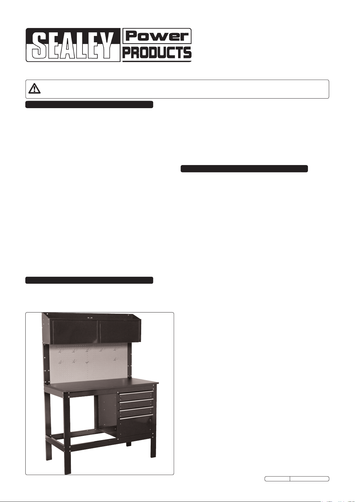
HEAVY DUTY STEEL WORKBENCH
WITH 4 DRAWERS & 2 TOP CABINETS
MODEL No: AP1205
Thank you for purchasing a Sealey product. Manufactured to a high standard this product will, if used according to these instructions and
properly maintained, give you years of trouble free performance.
IMPORTANT: PLEASE READ THESE INSTRUCTIONS CAREFULLY. NOTE THE SAFE OPERATIONAL REQUIREMENTS, WARNINGS & CAUTIONS.
USE THE PRODUCT CORRECTLY AND WITH CARE FOR THE PURPOSE FOR WHICH IT IS INTENDED. FAILURE TO DO SO MAY CAUSE
DAMAGE AND/OR PERSONAL INJURY AND WILL INVALIDATE THE WARRANTY. PLEASE KEEP INSTRUCTIONS SAFE FOR FUTURE USE.
1. SAFETY INSTRUCTIONS1. SAFETY INSTRUCTIONS
WARNING! Ensure Health & Safety, local authority, and
general workshop practice regulations are adhered to when
assembling and using this bench.
Locate bench in a suitable, well lit work area.
Use adequate manpower when assembling and moving this
bench.
WARNING! Use bench on level and solid ground only,
preferably concrete.
DO NOT use the bench outdoors and DO NOT get the bench
wet or use in damp or wet locations or areas where there is
condensation.
Keep the work area clean, uncluttered and ensure there is
adequate lighting.
Keep the bench clean and tidy in accordance with good
workshop practice.
Keep children and unauthorised persons away from the work area.
DO NOT use the bench for any purpose other than that for
which it is designed.
DO NOT undertake work on the bench without the workpiece
being adequately secured. Use clamps or a vice (not included -
available from your Sealey dealer) to secure the workpiece.
Lower heavy loads onto the worktop gently to avoid excessive
impacts to the worktop.
DO NOT clean the bench with any solvents which may damage
the surface or the protective coating on the worktop.
DO NOT stand on this product.
DO NOT use excessive force to open and close drawers.
DO NOT exceed weight limits - see specifications.
2. INTRODUCTION & SPECIFICATION
Heavy-duty steel powder-coated workbench with laminated
worktop. Four drawers on smooth 25mm roller ball-bearings
and two top storage cupboards. Pegboard back panel with
hooks for convenient tool storage.
Original Language Version
Dimensions:
Overall size (W x D x H): ..........1205mm x 620mm x 1735mm
Overall worktop size(W x D): ............... 1205mm x 590mm
Small drawer (W x D x H): ........... 430mm x 455mm x 80mm
Large drawer (W x D x H): .......... 430mm x 455mm x 222mm
Maximum Weight Limits:
Workbench: ...................................... 545kg
Drawers - (small): ....................................11kg
(large): ................................... 16kg
Pegboard:......................................... 29kg
Top shelf: ......................................... 27kg
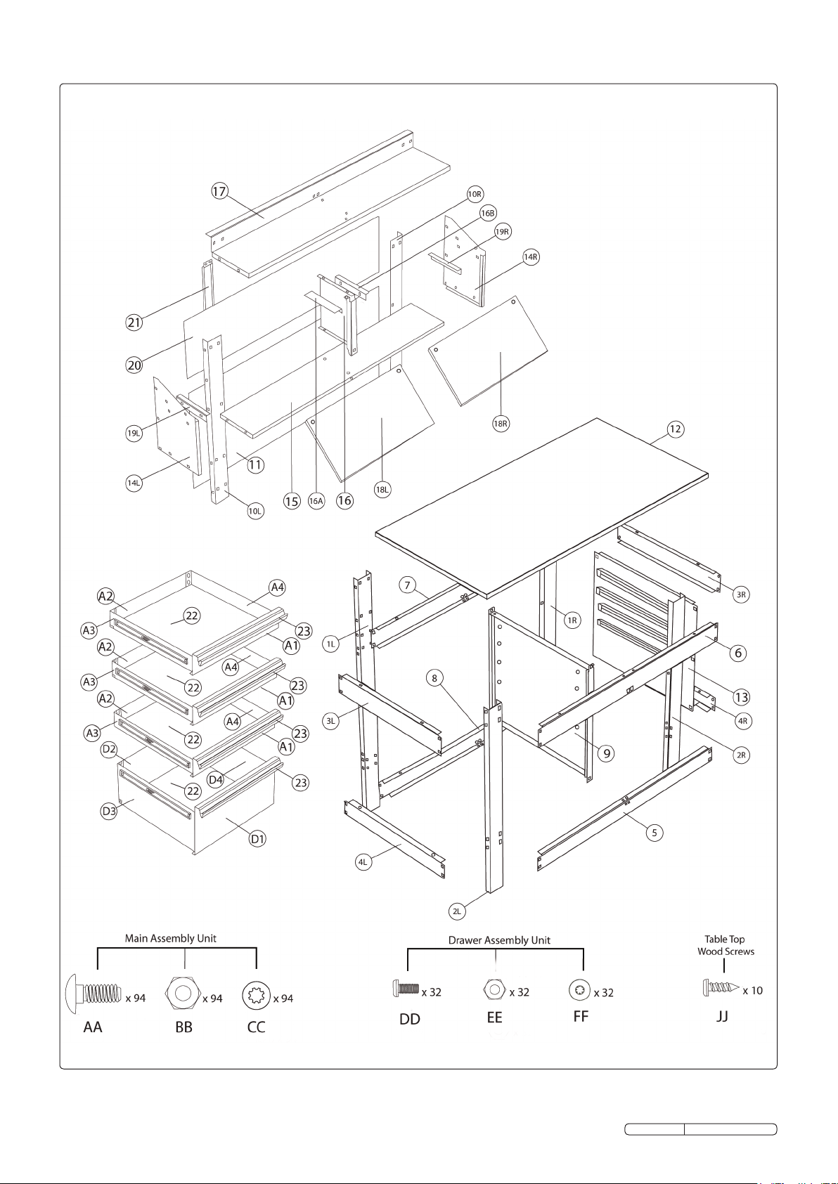
3. CONTENTS
Unpack the product and check the contents against the list below
and the illustration overleaf. Should any items be missing or
damaged contact your Sealey dealer.
ITEM DESCRIPTION
01L Support back leg (left)
01R Support back leg (right)
02L Support front leg (left)
02R Support front leg (right)
03L Short cross bracing (left)
03R Short cross bracing (right)
04L Short cross bracing (left)
04R Short cross bracing (right)
5 Long cross bracing (front-down)
6 Long cross bracing (front-up)
7 Long cross bracing (back-up)
8 Long cross bracing (back-down)
9 Centre wall with drawer rails
10L Left extension post
10R Right extension post
11 Pegboard
12 Worktop
13 Drawer side
14L Shelf bracing (left)
14R Shelf bracing (right)
15 Shelf bottom
16 Middle divider of shelf
16A Middle shelf divider rail (left)
16B Middle shelf divider rail (right)
17 Upper shelf
18L Top left door
18R Top right door
19L Rail of top left door
19R Rail of top right door
20 Back board of shelf
21 Pegboard support bar
22 Drawer Bottom (x4)
23 Aluminium handle cover for drawer (x4)
A1 Drawer front (x3)
A2 Drawer rear (x3)
A3 Drawer - Left side (x3)
A4 Drawer - Right side (x3)
D1 Drawer front
D2 Drawer rear
D3 Drawer - Left side
D4 Drawer - Right side
AA M6 bolt (x94)
BB M6 nut (x94)
CC M6 washer (x94)
DD M5 bolt (x32)
EE M5 nut (x32)
FF M5 washer (x32)
JJ Screw (x10)
AP1205 Issue No.1 - 26/09/11
Page 2
Original Language Version
AP1205 Issue No.1 25/09/11
Page 3

4. ASSEMBLY
Fig.1
NOTE: Tools required for assembly: spanner (included),
#2 cross-head screwdriver and pliers (not included).
4.1. Use 8 AA bolts, 8 BB nuts and 8 CC washers. Align holes
on cross bracing (3L) and (4L) to table legs (1L and 2L).
Insert 8 (AA) bolts through matching holes as shown above
- four bolts per cross bracing. Fasten with 8 washers (CC)
and 8 nuts (BB).
Do not over tighten.
Fig.2
4.2. Use 8 AA bolts, 8 BB nuts and 8 CC washers.
Align holes on cross bracing (3R) and (4R) to table legs
(1R) and (2R). Insert 8 (AA) bolts through matching holes
as shown above - four bolts per cross bracing.
Fasten with 8 washers (CC) and 8 nuts (BB).
Do not over tighten.
Fig.3
4.3. Use 16 AA bolts, 16 BB nuts and 16 CC washers.
Align holes from cross bracing pieces (5 and 8) to the
complete table leg ends from previous steps. Ensure labels
on pieces (5 and 8) have arrows facing up and square holes
are on the top. Insert 2 (AA) bolts through left and right side
of lower front cross bracings (5) - Fasten with 2 washers
(CC) and 2 nuts (BB). Repeat for lower back cross bracing
(8). Repeat steps for top cross bracing pieces (6 and 7),
ensure labels on pieces (6 and 7) have arrows facing up
and round holes are on the top. Do not over tighten.
Fig.4
NOTE: If you wish to install the drawers on the LEFT side, go to
steps 4.22 to 4.27.
Installation of drawers on left side will take an additional
1 hour approximately.
4.4. Use 4 AA bolts, 4 BB nuts and 4 CC washers.
Take centre wall (9), with drawer rails facing to the right of
the table, and fasten to frame of table using 4 (AA) bolts,
4 (CC) washers and 4 (BB) nuts.
Do not over tighten.
Original Language Version
AP1205 Issue No.1 25/09/11
Page 4

Fig.5
Fig.6
4.5. Use 8 AA bolts, 8 BB nuts and 8 CC washers.
Align holes on cross bracing (3L) and (4L) to table legs
(1L and 2L). Insert 8 (AA) bolts through matching holes as
shown above - four bolts per cross bracing.
Fasten with 8 washers (CC) and 8 nuts (BB).
Do not over tighten.
Fig.7
4.6. Use 8 AA bolts, 8 BB nuts and 8 CC washers.
Align holes on cross bracing (3L) and (4L) to table legs
(1L and 2L). Insert 8 (AA) bolts through matching holes as
shown above - four bolts per cross bracing.
Fasten with 8 washers (CC) and 8 nuts (BB).
Do not over tighten.
Fig.8
4.7. Use 8 AA bolts, 8 BB nuts and 8 CC washers.
With drawer rails facing inward, take drawer frame (13) and
fasten to body of frame using 8 (AA) bolts, 8 (CC) washers
and 8 (BB) nuts.
Do not over tighten.
Original Language Version
4.8. Use 3 AA bolts, 3 BB nuts and 3 CC washers.
Align holes of the left side shelf bracing (14L), and match
them to the peg board frame (10L). Fasten using 3 (AA)
bolts, 3 (CC) washers and 3 (BB) nuts.
Do not over tighten.
AP1205 Issue No.1 25/09/11
Page 5

Fig.9
Fig.10
4.9. Use 3 AA bolts, 3 BB nuts and 3 CC washers.
Align holes of the right side shelf bracing (14R), and
match them to the pegboard frame (10R).
Fasten using 3 (AA) bolts, 3 (CC) washers and 3 (BB) nuts.
Do not over tighten.
Fig.11
4.10. Use 4 AA bolts, 4 BB nuts and 4 CC washers.
Align the holes of the bottom of the shelving unit (15) and
match them to the side shelf bracing (14L) and (14R).
Fasten using 4 (AA) bolts, 4 (CC) washers and 4 (BB) nuts.
Do not over tighten.
Fig.12
4.11. Use 4 AA bolts, 4 BB nuts and 4 CC washers.
Take the middle shelf divider (16) and align holes with the
bottom shelving. Fasten using 2 (AA) bolts, 2 (CC) washers
and 2 (BB) nuts.
Take the left middle shelf divider rail (16A) and align it with
the right middle shelf divider rail (16B) making sure the
middle shelf divider (16) is in between. Fasten using 2 (AA)
bolts, 2 (CC) washers and 2 (BB) nuts.
Do not over tighten.
Original Language Version
4.12. Use 8 AA bolts, 8 BB nuts and 8 CC washers.
Taketheuppershelf(17)andlayatsothatitisrestingon
top of the shelf divider. Align holes of upper shelf (17) to
match the left and right side shelf bracing.
Take 3 (AA) bolts and insert them into the left shelf bracing,
fasten with 3 (CC) washers and 3 (BB) nuts.
Repeat previous step to attach the upper shelf (17) to the
right shelf bracing.
Take 2 (AA) bolts and insert them into the top part of shelf
divider, fasten with 2 (CC) washers and 2 (BB) nuts.
NOTE: Now tighten all fasteners on the workbench
upon completion of Step 4.12.
AP1205 Issue No.1 25/09/11
Page 6

Fig.13
Fig.14
4.13. Take the top left door (18L) and place onto rail of the middle
shelf divider (16).
Ensure that the wheel is resting onto the rail of middle shelf
divider.
You may have to insert the door at an angle to ensure it sits
securely on the rail of the middle shelf divider.
Fig.15
4.14. Use 2 AA bolts, 2 BB nuts and 2 CC washers.
Taketheleftshelfrail(19L)andtontothewheelofthetop
left door (left side). Lifting both the left shelf rail (19L) and
the top left door (18L), align the holes of (19L) with
the holes of the left side shelf bracing (14L). Fasten 19L to
14L with 2 (AA) bolts, with 2 (CC) washers and 2 (BB)
nuts.
Do not over tighten.
Fig.16
4.15. Take the top right door (18R) and place onto rail of the
middle shelf divider (16). Ensure that the wheel is resting
onto the rail of middle shelf divider.
You may have to insert the door at an angle to ensure it sits
securely on the rail of the middle shelf divider.
Original Language Version
4.16. Use 2 AA bolts, 2 BB nuts and 2 CC washers.
Taketherightshelfrail(19R)andtontothewheelofthe
top right door (right side). Lifting both the right shelf rail
(19R) and the top left door (18R), align the holes of (19R)
with the holes of the right side shelf bracing (14R).
Fasten 19R to 14R with 2 (AA) bolts, with 2 (CC) washers
and 2 (BB) nuts
Do not over tighten.
AP1205 Issue No.1 25/09/11
Page 7

Fig.17 Fig.18
4.17. Use 4 AA bolts, 4 BB nuts and 4 CC washers.
Rest the drawer backing (20) on top of the pegboard (11).
Take 4 (AA) bolts and place through pegboard frame (10R)
and (10L). Fasten and tighten with 4 (CC) washers and 4
(BB) nuts.
Do not over tighten.
Fig.19
4.18. Use 4 AA bolts, 4 BB nuts and 4 CC washers.
Align the holes of the pegboard support bar (21) to the
holes of the cross bracing piece (7) as well as the upper
shelf (17). Insert 4 (AA) bolts through holes and fasten
using 4 (CC) washers and 4 (BB) nuts.
Do not over tighten.
Fig.20
4.19. Align holes of front drawer (A1) with left and right side of
drawer (A3 & A4). Insert 2 (DD) bolts per side. Fasten
using 2 (FF) lock washers and 2 (EE) nuts.
Align holes of rear drawer (A2) with left and right side of
drawer (A3 & A4). Insert 2 (DD) bolts per side. Fasten
using 2 (FF) lock washers and 2 (EE) nuts.
Tighten all fasteners - Do not over tighten.
Insert wooden drawer bottom (22) so that it rests on lip of
drawers.
Slide aluminium handle cover (23) over the top of the front
drawer. Repeat for remaining small drawers.
Original Language Version
4.20. Align holes of front drawer (D1) with left and right side of
drawer (D3 & D4). Insert 2 (DD) bolts per side. Fasten
using 2 (FF) lock washers and 2 (EE) nuts.
Align holes of rear drawer (D2) with left and right side of
drawer (D3 & D4). Insert 2 (DD) bolts per side. Fasten
using 2 (FF) lock washers and 2 (EE) nuts.
Tighten all fasteners - Do not over tighten.
Insert wooden drawer bottom (22) so that it rests on lip of
drawers.
Slide aluminium handle cover (23) over the top of the front
drawer.
AP1205 Issue No.1 25/09/11
Page 8

Fig.21
Fig.22
Reversing Drawer Rails
for Left Hand Fitment
4.21. Empty the drawer and fully extend before removing.
Lift or lower (depending on the slide) the release lever on
both sides. Slowly pull the drawer out to remove from table.
To re-install, align the drawer rails and slowly push the
drawer into the table until the drawer stops.
Go to step 4.28.
Fig.23
4.22. Remove both screws attaching drawer rails to centre walls.
Flip drawer rails 180º to face the other direction and fasten
with both screws. Repeat the above steps for the other
three drawer rails.
Fig.24
4.23. Use 4 AA bolts, 4 BB nuts and 4 CC washers.
Take centre wall (9), with drawer rails facing to the left of
the table, and fasten to the frame of the table using 4 (AA)
bolts, 4 (CC) washers and 4 (BB) nuts.
Do not over tighten.
Original Language Version
4.24. Use 12 AA bolts, 12 BB nuts and 12 CC washers.
Take the pegboard (11) and place it against the back
of the table frame so that the power bar hole (PB) is on the
bottom right as shown above. Align screw holes
of pegboard (11) against the holes of the table frame.
Taking the left and right pegboard frame (10L and 10R),
sandwich the pegboard between (1L) and (10L). Repeat
this procedure, sandwiching Pegboard between (1R) and
(10R). Fasten pegboard frame against frame of table by
using 6 (AA) bolts, 6 (CC) washers and 6 (BB) bolts on each
side. Do not over tighten.
AP1205 Issue No.1 25/09/11
Page 9

Fig.25
Fig.26
4.25. Use 10 JJ screws.
Align pre-drilled holes on bottom of table top to the round
holes of the table frame. Using 10 (JJ) wood screws, fasten
table top to frame of table. Tighten screws using a
screwdriver.
Do not over tighten.
Fig.27 Fig.28
4.26. Slide the drawer rails in and out in order to remove both
screws attaching the drawer rails to the drawer frame.
Flip drawer rails 180º to face the other direction and fasten
with both screws.
Repeat the above steps for the other three drawer rails.
Do not over tighten.
4.27. Use 8 AA bolts, 8 BB nuts and 8 CC washers.
With drawer rails facing inward, take drawer frame (13) and
fasten to body of frame using 8 (AA) bolts, 8 (CC) washers
and 8 (BB) nuts.
Do not over tighten.
Now return to Step 4.8. to complete assembly.
Original Language Version
4.28. This workbench MUST be attached to a studded or concrete
wall. Only use material appropriate hardware per your
local building codes. Failure to do so may cause personal
injury or product damage.
Insert mounting hardware through the pre-drilled hole in
upper shelf (17). An additional pre-drilled hole is located in
cross bracing piece (7). If unable to secure through upper
shelf (17) securely mount workbench through cross bracing
piece (7). Use appropriate hardware only.
Do not over tighten.
AP1205 Issue No.1 25/09/11
Page 10

5. MAINTENANCE
5.1. Lubricate the slides of the drawers periodically with a smear of grease.
5.2. The drawer fronts, drawer trim, and other surfaces should be cleaned periodically with a mild detergent and water.
5.3. Carpolishwillpreservetheworkbench'snish.Applythepolishasyouwouldtoavehicle.Thepolishwillalsohelpprotectthe
workbench against scratches.
5.4. Greaseandoilcanberemovedwithmoststandardcleaninguids.Forsafetyreasons,useanonammablecleaninguid.
NOTE: It is our policy to continually improve products and as such we reserve the right to alter data, specifications and component parts without prior notice.
IMPORTANT: No liability is accepted for incorrect use of this product.
WARRANTY: Guarantee is 12 months from purchase date, proof of which will be required for any claim.
INFORMATION: For a copy of our latest catalogue and promotions call us on 01284 757525 and leave your full name and address, including postcode.
Sole UK Distributor, Sealey Group,
Kempson Way, Suffolk Business
Park, Bury St. Edmunds, Suffolk,
IP32 7AR
Original Language Version
01284 757500
01284 703534
www.sealey.co.uk
sales@sealey.co.uk
AP1205 Issue No.1 25/09/11
 Loading...