

ADJUSTABLE GEARBOX SUPPORT 500KG
IMPORTANT: PLEASE READ THESE INSTRUCTIONS CAREFULLY. NOTE THE SAFE OPERATIONAL REQUIREMENTS, WARNINGS & CAUTIONS. USE
THE PRODUCT CORRECTLY AND WITH CARE FOR THE PURPOSE FOR WHICH IT IS INTENDED. FAILURE TO DO SO MAY CAUSE DAMAGE AND/OR
PERSONAL INJURY AND WILL INVALIDATE THE WARRANTY. KEEP THESE INSTRUCTIONS SAFE FOR FUTURE USE.
CAPACITY SUITABLE FOR MODELS 300ETJ.V2
AND 500ETJ.V2
MODEL NO: ADT7.V2
Thank you for purchasing a Sealey product. Manufactured to a high standard, this product will, if used according to these instructions,
and properly maintained, give you years of trouble free performance.
Refer to
instruction
manual
Wear protective
gloves
Wear protective
clothing
Wear safety
footwear
1. SAFETY
WARNING! Ensure all preliminary checks are carefully carried out before using gearbox support and transmission jack.
WARNING! Follow all of the safety instructions issued with the transmission jack.
WARNING! Ensure load is placed level and centrally on gearbox support and is fixed in place before attempting to lift, lower, or
transport load. Always use load restraint chains and attachments to stabilise and secure the load to the gearbox support.
9 Before use ensure the transmission weight and size DO NOT exceed the capacity of the gearbox support or the transmission jack.
9 The gearbox support is heavy, care should be taken when placing onto the transmission jack.
9 Ensure that the sliding bracket and chain mount bracket nuts and bolts are fully tightened when the gearbox support is loaded.
9 Care should be taken when using the gearbox support and vertical transmission jack in conjunction with a vehicle lift to ensure that the
vehicle is not lowered whilst the jack is in position.
9 Before storing ensure gearbox support is clean and free of grease and oil.
9 Store in a safe, dry childproof location.
8 DO NOT use the gearbox support without restraint chains.
8 DO NOT replace the chains with an inferior form of restraint.
8 DO NOT allow untrained persons to use the gearbox support.
8 DO NOT move the transmission jack, with or without a load, with the gearbox support in the raised position.
8 DO NOT use the gearbox support for any purpose other than for vehicle transmissions.
2. iINTRODUCTION
Fully adjustable saddle with forward, backward and side to side tilt. Suitable for use with Model Nos: 300ETJ.V2 and 500ETJ.V2.
3. iSPECIFICATION
Model No: .................................................................ADT7.V2
Capacity: ......................................................................500kg
Compatibility: ....................................300ETJ.V2, 500ETJ.V2
Net weight
.................................................................12.02kg
fig.
1
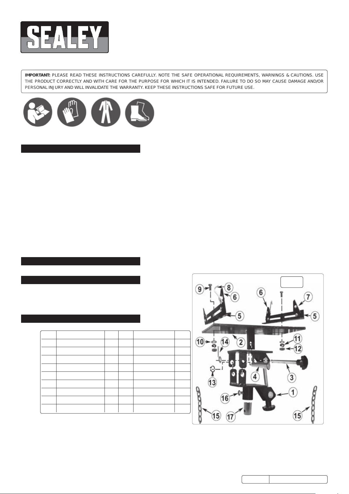
4. ASSEMBLY
Item Description Qty Item Description Qty
1 Main Support 01 10 Flat Washer 06
2 Support Plate 01 11 Spring Washer 10
3 Adjuster Screw 02 12 M10 Nut 10
4 Pivot Pin 01 13 Circlip 02
5 Sliding Bracket 02 14 Split Pin 01
6 Chain Mount Bracket 04 15 Chain 02
7 M8 Bolt and Nut 02 16 Retaining Bolt 02
8 Chain Hook 02 17 Reduction sleeve 01
9 M10 x 30mm Bolt 06
WARNING! Failure to assemble the gearbox support correctly may result in serious damage and/or personal injury. Unpack
the product and check contents against the contents list. Should there be any damaged or missing parts contact your supplier
immediately.
4.1. ASSEMBLY (refer to fig.1)
4.1.1. Position the support plate (2) on a flat surface with the bracket facing upwards. Place the main support (1) over the support plate (2) so
that the bracket fits into the slot on the main support (1).
© Jack Sealey Limited
Original Language Version
ADT7.V2 Issue 3 (H, F) 07/09/18

4.1.2. Align the adjuster screw (3) so that it passes through the bracket on the main support (1) and screws into the bracket on the support
plate (2). Continue to screw the adjuster screw (3) all the way through the support plate bracket until it completely protrudes from the
other side. Fit a flat washer (10) over the end of the adjuster screw (3) and continue to turn the adjuster screw (3) until the flat washer (10)
makes contact with the inside face of the opposite bracket and the end of the adjuster screw (3) is protruding through. Place a flat washer
(10) over the protruding end of the adjuster screw (3) at the outside face of the bracket and fit the split pin (14) through the hole in the end
of the adjuster screw (3).
4.1.3. Align the holes in the pivot brackets on the main support (1) so that the pivot pin (4) can be inserted. Secure the pivot pin (4) with the
circlips (13).
4.1.4. Attach the chain to the chain mounting brackets (6) using M8 bolts and nuts (7) and the chain hooks (8) to the chain mounting brackets
(6) using M10 nuts (12) and spring washers (11). It is not necessary to tighten the nuts fully until loading the gearbox support.
4.1.5. Attach the chain mounting brackets (6) to the sliding brackets (5) using four M10 x 30mm bolts (9). Use flat washers (10), spring washers
(11) on the nut (12) side only. It is not necessary to tighten the nuts fully until loading the gearbox support. The chain fixing (7) and the
chain hook (8) should be facing to the outer edges of the sliding brackets (5).
4.1.6. Place the assembled main support (1) and support plate (2) on to a suitable transmission jack. Attach each assembled sliding bracket (5)
to the slots in the support plate (2) using a M10 x 30mm bolt (9), flat washer (10), spring washer (11) and M10 nut (12). It is not necessary
to fully tighten the nuts until loading the gearbox support.
4.1.7. The gearbox support is now ready for use.
5. OPERATION
WARNING! DO NOT use gearbox support if any suspect part is found, or if it is believed to have been subjected to abnormal load or
shock. Immediately remove from service and contact your authorised service agent.
WARNING! Always read, understand and implement the safety and operating instructions supplied with the gearbox support and those
supplied with the transmission jack it is to be used with. (Note: Transmission jack not supplied).
5.1. With transmission jack fully down remove existing saddle and t the ADT7.V2. NOTE: The ADT7.V2 will t directly to the ETJ500.V2.
In order to t ADT7.V2 to the ETJ300.V2 it will be necessary to use the reduction sleeve provided (g.1-17). Tighten retaining bolt (16).
5.2. REMOVING GEARBOX. Loosen all gearbox fixing bolts leaving them finger tight.
5.2.1. Raise the gearbox support close to the gearbox and adjust the angle of the support plate (2) using the adjusting screws (3).
5.2.2. Position the sliding brackets (5) and the chain mount brackets to best support and locate the transmission, ensuring that all nuts and bolts
are tightened.
5.2.1. Feed the chains (15) over the top of the gearbox and attach to the chain hooks (8) leaving as little slack in the chains as possible. Fully
tighten the chains (15) using the adjusters on the chain hooks (8).
5.2.2. Remove all gearbox fixings. Disconnect drive shaft. Ensure that the gearbox is stable on the support. Detach gearbox and lower away
from underside of vehicle.
5.3. REFITTING GEARBOX.
5.3.1. Secure the repaired/new gearbox to the support plate (2) using the chains (15). Ensure that the sliding brackets (5) and the chain mount
brackets (6) are in a position to best support the transmission and all the nuts are fully tightened.
5.3.2. Raise the gearbox into the required position underneath the vehicle and make fine adjustments to the positioning using the adjuster
screws.
5.3.3. When the gearbox is in position and properly aligned with its fixing holes, insert all bolts finger tight before progressively
tightening them to the correct specified torque settings. (See vehicle service manual).
5.3.4. Remove chains (15) from gearbox and lower support away from underside of vehicle.
6. MAINTENANCE
6.1. Periodically lubricate the gearbox support pivot points and the adjuster screws (3).
6.2. Regularly check all xings for correct tightness.
ENVIRONMENT PROTECTION
Recycle unwanted materials instead of disposing of them as waste. All tools, accessories and packaging should be sorted, taken to
a recycling centre and disposed of in a manner which is compatible with the environment. When the product becomes completely
unserviceable and requires disposal, drain any fluids (if applicable) into approved containers and dispose of the product and fluids
according to local regulations.
Note: It is our policy to continually improve products and as such we reserve the right to alter data, specifications and component parts without prior
notice.
Important: No Liability is accepted for incorrect use of this product.
Warranty: Guarantee is 12 months from purchase date, proof of which is required for any claim.
Sealey Group, Kempson Way, Suffolk Business Park, Bury St Edmunds, Suffolk. IP32 7AR
01284 757500 01284 703534 sales@sealey.co.uk www.sealey.co.uk
© Jack Sealey Limited
Original Language Version
ADT7.V2 Issue 3 (H, F) 07/09/18
 Loading...