

PARAFFIN/DIESEL HEATERS
INSTRUCTION MANUAL FOR MODELS:
AB80.V5 AB100.V5 AB160.V5 AB200.V2 AB602.V4 AB801.V5
Thank you for purchasing a Sealey product. Manufactured to a high standard this product will, if used according to these instructions
and properly maintained, give you years of trouble free performance.
IMPORTANT: PLEASE READ THESE INSTRUCTIONS CAREFULLY. NOTE THE SAFE OPERATIONAL REQUIREMENTS, WARNINGS AND
CAUTIONS. USE THE PRODUCT CORRECTLY AND WITH CARE FOR THE PURPOSE FOR WHICH IT IS INTENDED. FAILURE TO DO SO MAY
CAUSE DAMAGE AND/OR PERSONAL INJURY AND WILL INVALIDATE THE WARRANTY. PLEASE KEEP INSTRUCTIONS SAFE FOR FUTURE USE.
1. SAFETY INSTRUCTIONS
1.1. ELECTRICAL SAFETY
WARNING! It is the responsibility of the owner and the operator to read, understand and comply with the following:
You must check all electrical products, before use, to ensure that they are safe. You must inspect power cables, plugs, sockets and any other
connectors for wear or damage. You must ensure that the risk of electric shock is minimised by the installation of appropriate safety devices. A
Residual Current Circuit Breaker (RCCB) should be incorporated in the main distribution board. We also recommend that a Residual Current
Device (RCD) is used. It is particularly important to use an RCD with portable products that are plugged into a supply which is not protected
by an RCCB. If in any doubt consult a qualified electrician. You may obtain a Residual Current Device by contacting your Sealey dealer.
You must also read and understand the following instructions concerning electrical safety.
1.1.1. The Electricity at Work Act 1989 requires all portable electrical appliances, if used on business premises, to be tested by a qualified
electrician, using a Portable Appliance Tester (PAT), at least once a year.
1.1.2. The Health & Safety at Work Act 1974 makes owners of electrical appliances responsible for the safe condition of those appliances
and the safety of the appliance operators. If in any doubt about electrical safety, contact a qualified electrician.
1.1.3. Ensure that the insulation on all cables and on the appliance is safe before connecting it to the power supply. See 1.1.1. and 1.1.2.
and use a Portable Appliance Tester.
1.1.4. Ensure that cables are always protected against short circuit and overload.
1.1.5. Regularly inspect power supply cables and plugs for wear or damage and check all
connections to ensure that none are loose.
1.1.6. Important: Ensure that the voltage marked on the appliance matches the power supply
to be used and that the plug is fitted with the correct fuse - see fuse rating at right.
1.1.7. DO NOT pull or carry the appliance by the power cable.
1.1.8. DO NOT pull the plug from the socket by the cable.
1.1.9. DO NOT use worn or damaged cables, plugs or connectors. Immediately have any faulty
item repaired or replaced by a qualified electrician. When an ASTA/BS approved UK
3 pin plug is damaged, cut the cable just above the plug and dispose of the plug safely.
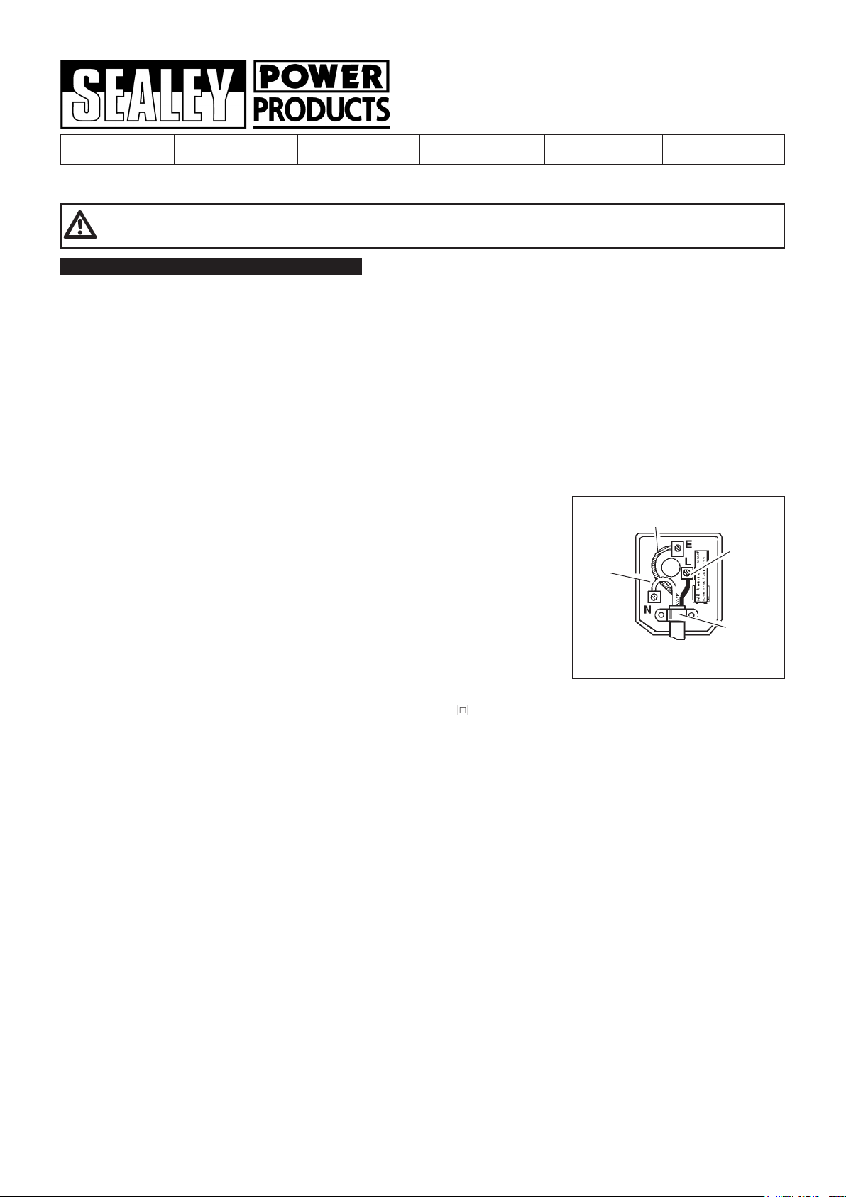
Fit a new plug according to the following instructions (UK only).
a) Connect the GREEN/YELLOW earth wire to the earth terminal ‘E’.
b) Connect the BROWN live wire to the live terminal ‘L’.
c) Connect the BLUE neutral wire to the neutral terminal ‘N’.
d) After wiring, check that there are no bare wires, that all wires have been correctly
connected, that the cable outer insulation extends beyond the cable restraint and that the
restraint is tight.
Double insulated products, which are always marked with this symbol , are fitted with live (brown) and neutral (blue) wires only.
To rewire, connect the wires as indicated above - DO NOT connect either wire to the earth terminal.
1.1.10. If an extension reel is used it should be fully unwound before connection. A reel with an RCD fitted is preferred since any appliance
plugged into it will be protected. The cable core section is important and should be at least 1.5mm2, but to be absolutely sure that the
capacity of the reel is suitable for this product and for others which may be used in the other output sockets, we recommend the use
of 2.5mm2 section cable.
Blue
Neutral
Wire
Yellow & Green
Earth Wire
Brown
Live
Wire
Cable
Restraint
FUSE RATING 13 AMP
1.2. GENERAL SAFETY
Check that the heater is in sound condition and good working order. Take immediate action to repair or replace damaged parts.
Use recommended parts only. Unapproved parts may be dangerous and will invalidate the warranty.
Only use paraffin or diesel to fuel your heater, in accordance with instructions contained in this manual.
WARNING! Only use heater in well ventilated areas. Ensure continuous ventilation is provided to the heater operating area. Allow at least
0.03ft² opening/1000Btu/h output (0.01m2/kW). This should be divided equally between floor and high level. Ventilation must be to the
outside of the premises in which the heater is to be operated. If your operating area has no direct access to clean fresh air we recommend
that you run a large gauge duct from the outside of the building to the back of the heater in order to provide a clean air intake. For more details see
Section 4.
Keep the heater a minimum of 3 metres from any combustible materials (i.e. wooden items, cloth, plastics, paper, etc).
Maintain a minimum distance of 50cm from non-combustible materials (i.e. brick, steel, concrete, etc).
Check the colour of the dome at the heater outlet to ensure that optimum heat output is maintained. (see Section 5.3).
WARNING! DO NOT use the heater near flammable material, liquids, solids, gases or compressed gas cylinders and the like.
DO NOT use the heater in closed rooms, living areas, basements or below ground level.
DO NOT allow untrained persons to operate the heater and DO NOT operate the heater without the cover.
DO NOT use an external fuel tank. Only use that which is part of the heater.
DO NOT stand or place any object less than 3 metres from the heater output.
DO NOT obstruct the air inlet and outlet sections of the heater.
DO NOT operate the heater when you are tired or under the influence of alcohol, drugs or intoxicating medication.
DO NOT over-fill the fuel container. Wipe up any spilt fuel immediately.
DO NOT touch the heater outlet or dome when first switched off as these are very hot and will take time to cool.
Ensure that the heater is correctly turned off when not in use and store in a safe, dry area, out of reach of children.
DO NOT leave the heater unattended when in use. Switch the heater off and unplug from the mains before leaving work area.
DO NOT unplug the AB200 to switch it off. Use the ON/OFF switch. This will allow the aftercooling fan to run for 2 mins after shutdown.
AB80.V5, AB100.V5 & AB160.V5, AB200.V2, AB602.V4, AB801.V5
- 3 - 280208
2. INTRODUCTION & SPECIFICATIONS
NOTE: Your heater is set to be used with paraffin, to adjust for diesel use refer to Section 4.
The Sealey AB heaters are made to DIN30697 standard and built to survive the rigor of bodyshops, workshops and large work areas (these
heaters are not for domestic use). A sensor will automatically cut off the motor and fuel supply if the flame is inadvertently extinguished. The
heater can be fuelled with paraffin or (with minor adjustments to air pressure systems) diesel. Diesel, however, will not burn as cleanly as
paraffin. DO NOT use any other type of fuel. A specially designed burner head in a stainless steel combustion chamber ensures a thorough
burn of fuel which results in economical use and maximum heating effect. The cast alloy compressor unit is protected by a large filter element
and the fuel line is fitted with an in-line filter to ensure trouble free operation. The AB heaters will operate for between 6 and 18 hours on a
single tank of fuel.
2.1. Specifications
Model: AB602.V4 AB200.V2 AB801.V5 AB80.V5 AB100.V5 AB160.V5
Output (Btu/h/kW): 51,250/15.1 210,865/61.3 80,000/23.5 80,000/23.5 100,000/29.4 160,000/47
Tank capacity : 11ltr 46LTR 11ltr 21ltr 30ltr 46ltr
Fuel oil: Paraffin/Diesel Paraffin/Diesel Paraffin/Diesel Paraffin/Diesel Paraffin/Diesel Paraffin/Diesel
Electrical input: 230V 5A 230V 3A 230V 5A 230V 5A 230V 5A 230V 5A
Approx. hours operation per filling: 14 10 6 11 13 13
Transport wheels: Not fitted Standard Not fitted Standard Standard Standard
Air flow (cfm): 206 770 300 300 412 770
Automatic shut-off: Yes Yes Yes Yes Yes Yes
Heated volume (ft3): 12,790 48,900 20,000 20,000 25,000 40,000
Heated volume (m3): 375 1385 585 585 700 1120
Net weight (kg): 16 45 20 26 31 41
Quality standard: CE Norm CE Norm CE Norm CE Norm CE Norm CE Norm
3. ASSEMBLY
Unpack the heater and check contents. Should there be any damaged or missing parts contact your
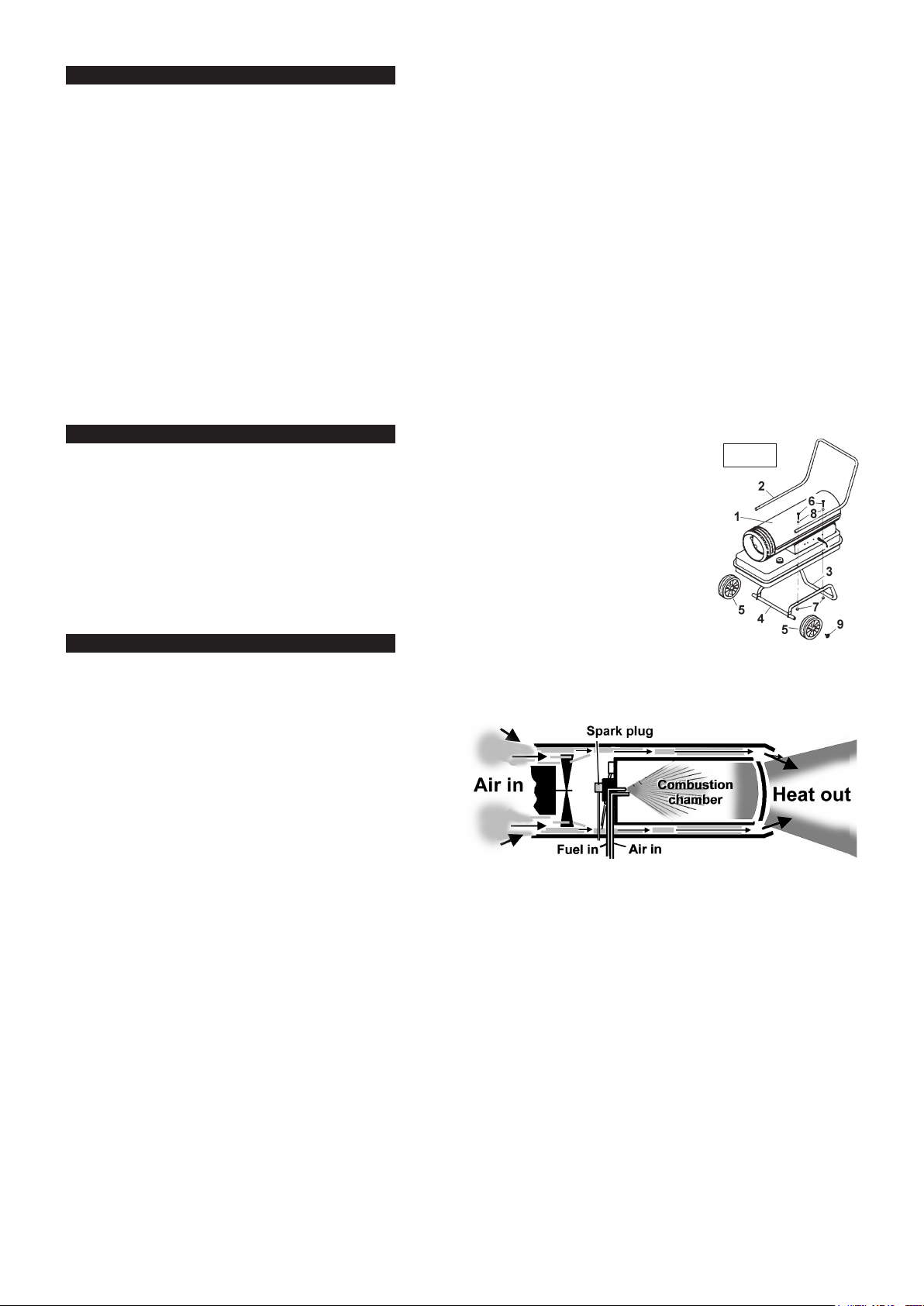
supplier immediately. If your model is supplied with wheels refer to fig.1 for assembly as follows:
3.1. Slide axle (4) through wheel support frame (3).
3.2. Install wheels (5) then cap nuts (9) on axle ends and tap lightly into place.
3.3. Place heater on wheel support frame and line up holes on the fuel tank flange with holes on the wheel
support frame.
3.4. Place handle on fuel tank flange and line up with the wheel support frame fixing holes. Insert bolts (6)
through the fuel tank flange and both frames and secure finger tight only with nuts (7) and washers (8).
3.5. When assembly is complete, securely tighten all nuts.
fig. 1
4. OPERATING CONDITIONS
4.1. Principles of heat generation
When the heater is switched on the air compressor draws in air, pressurises it and passes it through an air line to the burner head
nozzle. The air flow causes fuel to be drawn from the tank. The fuel and air mix is then sprayed into the combustion chamber.
The mixture is automatically ignited by the spark plug and a
high temperature heat stream is generated in the combustion
chamber. Air is drawn into the unit by a fan and is pushed
around the cool chamber situated between combustion
chamber and outer casing. This fast flowing air sucks the heat
stream out of the combustion chamber, providing the required
heat. Heat will cause the steel dome in the heater outlet to
glow. The intensity of this glow is an indication of the output. If
the system malfunctions a “flame-out” control will operate and
automatically cut off the motor and fuel supply. Should this
happen, switch off machine and unplug from mains supply.
Refer to trouble shooting chart in Section 7 and/or return unit to supplier for maintenance.
4.2. Fuel
The AB series will operate with two types of fuel, paraffin or diesel. Before operating the heater you must determine which type of
fuel you will use in order to effect the correct heater settings. The following information must be understood before use.
4.2.1. Paraffin
The heat output is governed by the compressor - the higher the air pressure the hotter the flame. The AB series heaters have had the
air pressure pre-set at the factory to accommodate paraffin (because it will burn more cleanly than diesel). When the heater is new
however (or when the unit has been returned from service) the settings may require minor adjustment to accommodate reductions in
air flow through a new air filter. Incorrect settings will cause flame problems and may emit fuel odours resulting in damage to the unit
and an uncomfortable working environment. Paraffin will sometimes cause condensation. If the unit is stored unused (i.e. during the
summer) such condensation will cause the fuel tank to corrode and, when next used, the flame to pulsate due to water in the tank.
To overcome the problem, paraffin must be drained off and replaced if the heater is to be unused for a long periods.
4.2.2. Diesel
AB series heaters are pre-set at the factory to accommodate paraffin. If diesel is used without changing the setting the air pressure
will be greater than is required resulting in an excessively hot flame which will damage the unit. Before using diesel the system must
be adjusted by decreasing the air pressure to the point at which the diesel will burn to generate the correct heat output. (See 5.2).
WARNING! Failure to adjust to the correct air pressure will damage the combustion chamber and invalidate your warranty.
The spark plug will require cleaning every 50 hours of use in order to remove carbon deposits (see Maintenance Section 6). We
recommend cleaning the plug at least once every standard working week if less than 50 hours.
4.3.
When used in the construction or agricultural industries ensure that the safety regulations in force are adhered to with regard to
distances from flammable materials and any other specified substances. Refer to General Safety in Section 1 for recommended
clearances.
AB80.V5, AB100.V5 & AB160.V5, AB200.V2, AB602.V4, AB801.V5
- 3 - 280208
WARNING! Air contaminants taken into the heater may affect the heat output, damage the unit and may cause health problems.
Example: Bodyshop filler dust will damage the motor bearing, clog the filter and compressor and contaminate the combustion chamber
causing flame flutter and health hazards. If contaminants are present the heater must be supplied with ducted clean air, see 4.4.
Please note that any parts damaged by filler dust will not be covered by warranty. Additionally, a cleaning charge will be made
for any heaters damaged by filler dust.
4.4. VENTILATION. ( Minimum recommended openings for fresh air intake.)
Model: AB602.V4 = 0.15m2 AB200.V2 = 0.6m2 AB801.V5 = 0.23m2 AB80.V5 = 0.23m2 AB100.V5 = 0.29m2 AB160.V5 = 0.47m2
WARNING! Only use the heater in well ventilated areas. Careful consideration must be given to the placing of the heater to provide safe
and comfortable heating. Ensure continuous ventilation is provided to the heater operating area. Allow at least 0.01m2/kW heater output.
This should be divided equally between floor and high level. A ventilation opening must run to the outside of the premises in which the
heater is to be operated. If the operating area has no direct access to clean fresh air we recommend you run a large gauge duct from
the outside of the building to the inlet of the heater in order to provide a clean air intake. Ensure that the duct is laid so as to not
compromise safety.
.
5. OPERATING INSTRUCTIONS
5.1. Running the heater on paraffin. The heater has been factory pre-set for paraffin and will produce
the correct heat output when first used from new. You should run the heater at the pre-set output in
order to ensure the long life, safety and reliability of the unit. Minor adjustments to heat output may
be required during the first 60 hours of use. These adjustments are made to the air pressure valve
(see fig.5.A). Once the unit has completed the running-in period it should not be necessary to alter
the air pressure again until a new air filter is fitted or a change of fuel takes place.
5.1.1. Ensure that the unit is unplugged from the mains supply.
5.1.2. Fill the fuel tank with paraffin. Do not over-fill. Wipe away any spillage before use.
5.1.3. Plug into the main power supply and switch on the heater. The heater will ignite and as the heat
builds to maximum (approximately two minutes) the dome at the output end of the heater will begin
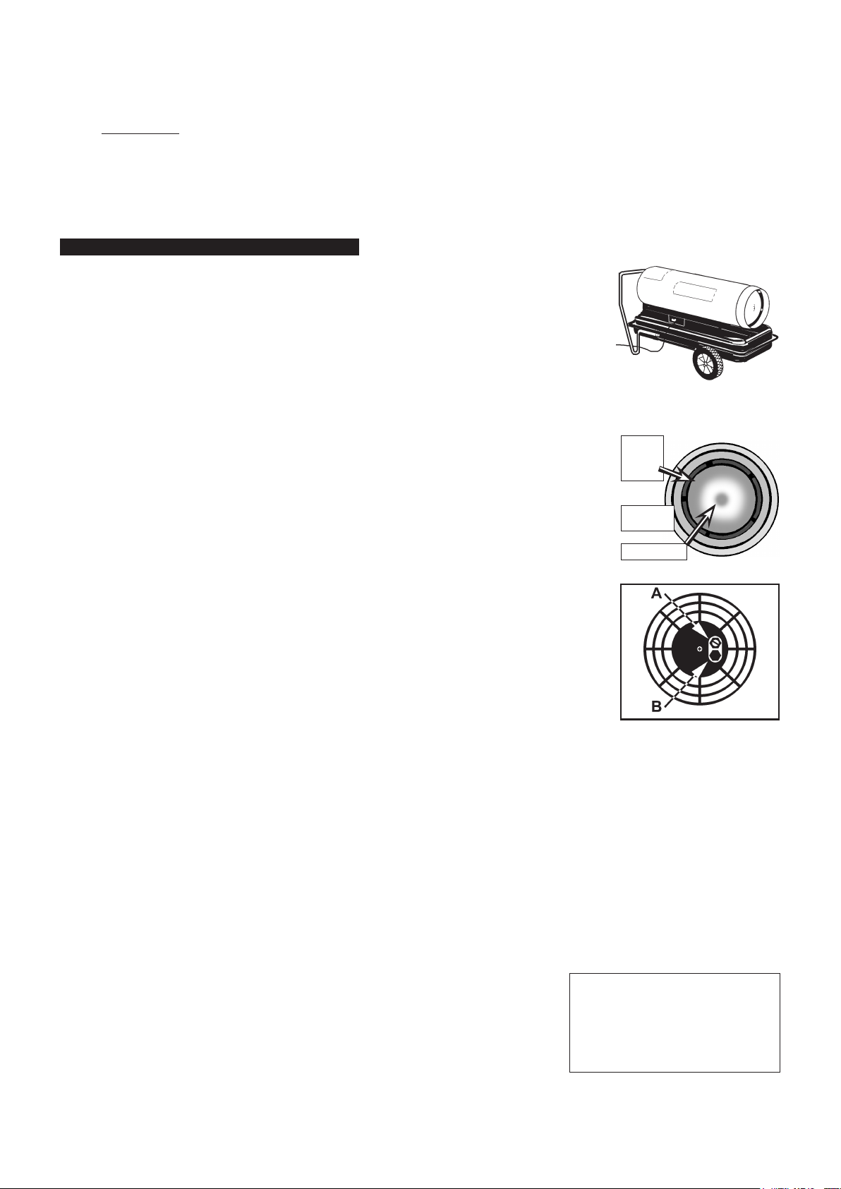
to glow. Observe the colour of the dome to check that the heater is producing the correct heat output, as indicated below. Stand at
least 3 metres away from heater to make observations.
a) NORMAL CHERRY RED IN THE MIDDLE PROGRESSING TO AN ORANGE ON THE
OUTSIDE RIM OF THE DOME (see fig.4).
b) TOO HOT ORANGE ALL OVER. WARNING! This output will damage the combustion
chamber and invalidate warranty.
c) TOO COOL ANY DULL GLOW PROGRESSING UPWARD TO CHERRY RED ALL OVER.
(Heater odour emissions will also indicate incorrect settings.)
5.1.4. To adjust the heat output, locate the air pressure valve (fig.5.A), which is in the
air inlet grille at the back of the unit. Hold the adjusting screw steady with a screwdriver and loosen
the locking nut. Turn the screw clockwise to increase the air pressure and thus increase the heat
output. Turn the screw anticlockwise to decrease the air pressure and thus decrease the heat
output. Make small adjustments only and give the heater time to stabilise before observing the
effect on the colour of the dome. When the colour is normal as described above in section 5.1.3.(a) tighten the locking nut.
5.1.5. Turn off the heater at the rocker switch and unplug from the mains supply (except for the AB200,
see section 5.2.6 below ). DO NOT touch the heater outlet as this will remain hot for
some time. Store in a dry, safe, childproof area.
centre portion of the
fig. 3
Bright
orange
glow
fig. 4
Cherry red
fig. 5
5.2. Running the heater on diesel. The heater has been pre-set in the factory for the use of paraffin.
Because diesel burns hotter than paraffin it will be necessary to decrease the air pressure to give
out the correct heat output. Failure to make this adjustment will damage the combustion
chamber and invalidate your warranty.
5.2.1. Ensure that the unit is unplugged from the mains supply.
5.2.2. Fill the fuel tank with diesel. Do not over-fill and wipe away any spillage before use.
5.2.3. Plug back into the mains supply and start the heater, run for two minutes before making any
adjustment to the air pressure valve. Locate the valve (fig.5.A) which is in the centre portion of the air inlet grille at the back of the unit.
Hold the adjusting screw steady with a screwdriver and loosen the locking nut. Turn screw half a turn anticlockwise to decrease the air
pressure, and thus decrease the heat output, to compensate for the hotter burning diesel fuel. Retighten the locking nut.
5.2.4. As the heat builds to maximum (approximately two minutes) the dome at the output end of the heater will begin to glow. Observe the
colour of the dome to check that the heater is producing the correct heat output as indicated above in section 5.1.3. Stand at least 3
metres away from heater output to make observations. Minor adjustments to heat output may be required during the first 60
hours of use. If necessary readjust the air pressure valve as indicated in section 5.1.4. to achieve the correct dome colour.
5.2.5. Turn off the heater at the rocker switch and unplug from the mains supply ( except for the AB200.V2, see section 5.2.6 below ).
DO NOT touch the heater outlet as this will remain hot for some time. Store in a dry, safe, childproof area.
5.2.6. Always shut down the AB200.V2 using the ON/OFF switch. Leave the heater plugged into the mains supply for at least 3
minutes. (The AB200.V2 is fitted with an aftercooling timer that allows the fan to rotate for approximately 2 minutes after shutdown, to
cool the combustion chamber and release residual heat.) NEVER SHUT DOWN THE HEATER BY PULLING OUT THE PLUG.
5.3. Monitoring the heat output. The heat output should be checked on a daily basis by observing the outlet dome operating colour, as
described in Section 5.1.3. If, after a period of time, the heat output begins to fall this indicates that either the unit requires
maintenance, as laid out in Section 6, or that the environmental conditions the unit is operating in are not correct, see Section 4.
DO NOT ATTEMPT TO TURN UP THE AIR PRESSURE TO COMPENSATE FOR HEAT LOSS as this could result in
damage to the combustion chamber and would invalidate the warranty.
5.3.1. If there is any doubt about the efficient operation of the heater, the air pressure should be
checked more exactly using a pressure gauge which will measure up to 30 p.s.i. and has
a 1/8” BSP thread. With the heater turned off and unplugged from the mains, remove
the threaded plug from below the air pressure valve and attach the gauge, see fig.5.B. Start
the heater and compare the pressure reading with the chart shown on the right. If the
reading differs from the chart this indicates that maintenance is required as laid out in
Section 6. You should also investigate whether the environmental conditions at the location
of the heater are suitable, with particular reference to the amount and quality of the air supply.
5.3.2. Turn off the heater as instructed in sections 5.1.5. & 5.2.5. Remove the gauge and replace the plug before turning on the heater again.
Working Pressures bar/psi
Diesel Paraffin
AB602.V4 0.26/3.77 0.28/4.06
AB200.V2 0.34/4.9 0.34/4.9
AB801.V5 0.26/3.77 0.33/4.78
AB80.V5 0.26/3.77 0.33/4.78
AB100.V5 0.30/4.35 0.36/5.22
AB160.V5 0.30/4.35 0.39/5.65
AB80.V5, AB100.V5 & AB160.V5, AB200.V2, AB602.V4, AB801.V5
- 3 - 280208
 Loading...